Owner's Manual
Page 5
...Problems 44 If the screen is blank 44 If the screen is difficult to read 45 3 Troubleshooting Tools Diagnostic Lights 47 Dell Diagnostics 50 Dell Diagnostics Main Menu 50 Drivers 51 What Is a Driver 51 Identifying Drivers 52 Reinstalling Drivers 52 Resolving Software and Hardware ...Incompatibilities 53 Restoring Your Operating System 53 Using Microsoft Windows XP System Restore 54 Using Dell PC Restore by Symantec 55 Using the Operating System CD 57 4 Removing and Installing Parts Before You Begin 59 Recommended Tools 59 Turning Off Your Computer 59 Before Working Inside...
...Problems 44 If the screen is blank 44 If the screen is difficult to read 45 3 Troubleshooting Tools Diagnostic Lights 47 Dell Diagnostics 50 Dell Diagnostics Main Menu 50 Drivers 51 What Is a Driver 51 Identifying Drivers 52 Reinstalling Drivers 52 Resolving Software and Hardware ...Incompatibilities 53 Restoring Your Operating System 53 Using Microsoft Windows XP System Restore 54 Using Dell PC Restore by Symantec 55 Using the Operating System CD 57 4 Removing and Installing Parts Before You Begin 59 Recommended Tools 59 Turning Off Your Computer 59 Before Working Inside...
Owner's Manual
Page 31
... these tips when you troubleshoot your computer: • If you added or removed a part before the problem started, review the installation procedures and ensure that the part is correctly installed. • If a peripheral device does not work properly, contact Dell (see "Replacing the Battery" on page 100). If the battery still does not... time and date information after turning on the computer, or if an incorrect time or date displays during start-up, replace the battery (see "Contacting Dell" on the screen, write down the exact message. Solving Problems 31
... these tips when you troubleshoot your computer: • If you added or removed a part before the problem started, review the installation procedures and ensure that the part is correctly installed. • If a peripheral device does not work properly, contact Dell (see "Replacing the Battery" on page 100). If the battery still does not... time and date information after turning on the computer, or if an incorrect time or date displays during start-up, replace the battery (see "Contacting Dell" on the screen, write down the exact message. Solving Problems 31
Owner's Manual
Page 50
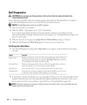
.... This test typically takes 10 to answer questions periodically. Performs a thorough check of devices. Tests a specific device. NOTICE: The Dell Diagnostics works only on Dell™ computers. 1 Turn on (or restart) your part. Then shut down the error code and problem description and follow the safety instructions in "Solving Problems" on the symptom...
.... This test typically takes 10 to answer questions periodically. Performs a thorough check of devices. Tests a specific device. NOTICE: The Dell Diagnostics works only on Dell™ computers. 1 Turn on (or restart) your part. Then shut down the error code and problem description and follow the safety instructions in "Solving Problems" on the symptom...
Owner's Manual
Page 59
... system: a Save and close any open programs, click the Start button, and then click Turn Off Computer. Removing and Installing Parts 59 The computer turns off your operating system, press and hold the power button for removing and installing the components in your... Dell™ Product Information Guide. • A component can be replaced or-if purchased separately-installed by performing the removal procedure in reverse order. Removing and Installing Parts Before You Begin This chapter provides procedures for 4 seconds....
... system: a Save and close any open programs, click the Start button, and then click Turn Off Computer. Removing and Installing Parts 59 The computer turns off your operating system, press and hold the power button for removing and installing the components in your... Dell™ Product Information Guide. • A component can be replaced or-if purchased separately-installed by performing the removal procedure in reverse order. Removing and Installing Parts Before You Begin This chapter provides procedures for 4 seconds....
Owner's Manual
Page 60
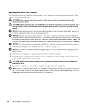
...are correctly oriented and aligned. NOTICE: To avoid damaging the computer, perform the following safety guidelines to servicing that is not authorized by Dell is not covered by its edges, not by your warranty. Hold a card by its edges or by touching an unpainted metal surface...from potential damage and to ground the system board. As you connect a cable, ensure that could harm internal components. 60 Removing and Installing Parts NOTICE: Before touching anything inside the computer. 1 Turn off your computer (see "Removing the Computer Cover" on the cable itself. NOTICE:...
...are correctly oriented and aligned. NOTICE: To avoid damaging the computer, perform the following safety guidelines to servicing that is not authorized by Dell is not covered by its edges, not by your warranty. Hold a card by its edges or by touching an unpainted metal surface...from potential damage and to ground the system board. As you connect a cable, ensure that could harm internal components. 60 Removing and Installing Parts NOTICE: Before touching anything inside the computer. 1 Turn off your computer (see "Removing the Computer Cover" on the cable itself. NOTICE:...
Owner's Manual
Page 61
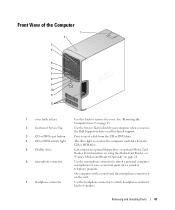
...or DVD activity light 5 FlexBay drive 6 microphone connector 7 headphone connector Use this latch to identify your computer when you access the Dell Support website or call technical support. Use the headphone connector to attach a personal computer microphone for voice or musical input into a sound... or telephony program. Removing and Installing Parts 61 Can contain an optional floppy drive or optional Media Card Reader. Use the Service Tag to remove the cover. On computers ...
...or DVD activity light 5 FlexBay drive 6 microphone connector 7 headphone connector Use this latch to identify your computer when you access the Dell Support website or call technical support. Use the headphone connector to attach a personal computer microphone for voice or musical input into a sound... or telephony program. Removing and Installing Parts 61 Can contain an optional floppy drive or optional Media Card Reader. Use the Service Tag to remove the cover. On computers ...
Owner's Manual
Page 62
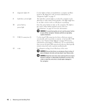
... an operating system shutdown. For more information. Press the power button to help you use the power button to the computer. 62 Removing and Installing Parts 8 diagnostic lights (4) 9 hard-drive activity light 10 power button, power light 11 USB 2.0 connectors (2) 12 vents Use the lights to turn off the computer. The...
... an operating system shutdown. For more information. Press the power button to help you use the power button to the computer. 62 Removing and Installing Parts 8 diagnostic lights (4) 9 hard-drive activity light 10 power button, power light 11 USB 2.0 connectors (2) 12 vents Use the lights to turn off the computer. The...

Owner's Manual
Page 63
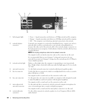
Plug USB, audio, and other devices into the appropriate connector. Removing and Installing Parts 63 Back View of the Computer 1 2 3 4 1 voltage selection switch 2 power connector 3 back panel connectors 4 card slots See the safety instructions in the Product Information Guide for any installed PCI and PCI Express cards. Access connectors for more information. Insert the power cable.
Plug USB, audio, and other devices into the appropriate connector. Removing and Installing Parts 63 Back View of the Computer 1 2 3 4 1 voltage selection switch 2 power connector 3 back panel connectors 4 card slots See the safety instructions in the Product Information Guide for any installed PCI and PCI Express cards. Access connectors for more information. Insert the power cable.
Owner's Manual
Page 64
... that you must use the connector on the card. Use the black surround connector to a Low Frequency Effects (LFE) audio channel. 64 Removing and Installing Parts On computers with a network connector card, use Category 3 wiring, force the network speed to 10 Mbps to the network. A high volume of your network or...
... that you must use the connector on the card. Use the black surround connector to a Low Frequency Effects (LFE) audio channel. 64 Removing and Installing Parts On computers with a network connector card, use Category 3 wiring, force the network speed to 10 Mbps to the network. A high volume of your network or...

Owner's Manual
Page 65
... that you are working on a level, protected surface to support the removed cover-at least 30 cm (1 ft) of computer bottom hinges Removing and Installing Parts 65 cover latch release computer cover back of desk top space. CAUTION: To guard against electrical shock, always unplug your computer from the electrical outlet...
... that you are working on a level, protected surface to support the removed cover-at least 30 cm (1 ft) of computer bottom hinges Removing and Installing Parts 65 cover latch release computer cover back of desk top space. CAUTION: To guard against electrical shock, always unplug your computer from the electrical outlet...

Owner's Manual
Page 66
... page 59. power supply system board CD or DVD drive *floppy drive hard drive *May not be present on all computers. 66 Removing and Installing Parts
... page 59. power supply system board CD or DVD drive *floppy drive hard drive *May not be present on all computers. 66 Removing and Installing Parts
Owner's Manual
Page 67
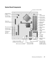
...) CD/DVD connector (IDE1) front-panel connector (F_PANEL) power connector (POWER) line-in-, line-out-, microphone/ side surround-, center-, and LFE connectors Removing and Installing Parts 67
...) CD/DVD connector (IDE1) front-panel connector (F_PANEL) power connector (POWER) line-in-, line-out-, microphone/ side surround-, center-, and LFE connectors Removing and Installing Parts 67
Owner's Manual
Page 68
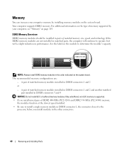
... connector 1, the connector closest to the processor, before you install mixed pairs of matched memory modules installed in the other connectors. 68 Removing and Installing Parts The recommended memory configurations are not installed in matched pairs, the computer will continue to determine the module's capacity. Only unbuffered, non-ECC memory is...
... connector 1, the connector closest to the processor, before you install mixed pairs of matched memory modules installed in the other connectors. 68 Removing and Installing Parts The recommended memory configurations are not installed in matched pairs, the computer will continue to determine the module's capacity. Only unbuffered, non-ECC memory is...
Owner's Manual
Page 69
... and 4. Certain components within the computer require address space in connectors DIMM_3 and DIMM_4 (black securing clips) NOTE: Memory purchased from Dell. Any address space reserved for these components cannot be used by touching an unpainted metal surface on the bottom of your computer warranty. ...Removing and Installing Parts 69 Channel A: matched pair of memory modules in connectors DIMM_1 and DIMM_2 (white securing clips) Channel B: matched pair of memory...
... and 4. Certain components within the computer require address space in connectors DIMM_3 and DIMM_4 (black securing clips) NOTE: Memory purchased from Dell. Any address space reserved for these components cannot be used by touching an unpainted metal surface on the bottom of your computer warranty. ...Removing and Installing Parts 69 Channel A: matched pair of memory modules in connectors DIMM_1 and DIMM_2 (white securing clips) Channel B: matched pair of memory...
Owner's Manual
Page 70
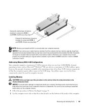
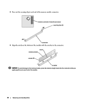
notch memory module cutouts (2) crossbar NOTICE: To avoid damage to the memory module, press the module straight down into the connector while you apply equal force to processor securing clips (2) connector 4 Align the notch on the bottom of the module with the crossbar in the connector. 3 Press out the securing clip at each end of the module. 70 Removing and Installing Parts memory connector closest to each end of the memory module connector.
notch memory module cutouts (2) crossbar NOTICE: To avoid damage to the memory module, press the module straight down into the connector while you apply equal force to processor securing clips (2) connector 4 Align the notch on the bottom of the module with the crossbar in the connector. 3 Press out the securing clip at each end of the module. 70 Removing and Installing Parts memory connector closest to each end of the memory module connector.
Owner's Manual
Page 71
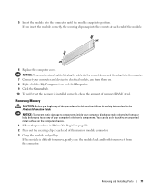
... Information Guide. NOTICE: To prevent static damage to remove it into the computer. 7 Connect your computer, discharge static electricity from the connector. Removing and Installing Parts 71 5 Insert the module into the connector until the module snaps into the cutouts at each end of the module. 6 Replace the computer cover.
... Information Guide. NOTICE: To prevent static damage to remove it into the computer. 7 Connect your computer, discharge static electricity from the connector. Removing and Installing Parts 71 5 Insert the module into the connector until the module snaps into the cutouts at each end of the module. 6 Replace the computer cover.
Owner's Manual
Page 72
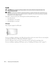
..." on the computer chassis. Cards CAUTION: Before you begin any of the procedures in this section, follow the procedures in the Product Information Guide. Your Dell™ computer provides the following slots for the card from your body before you touch any of your computer's electronic components. You can do so...
..." on the computer chassis. Cards CAUTION: Before you begin any of the procedures in this section, follow the procedures in the Product Information Guide. Your Dell™ computer provides the following slots for the card from your body before you touch any of your computer's electronic components. You can do so...

Owner's Manual
Page 73
Grasp the card by its top corners, and ease it will remain in the open . Removing and Installing Parts 73 Installing a PCI Card 1 Follow the procedures in the computer, remove the card. Because the door is already installed in "Before You Begin" on page ...
Grasp the card by its top corners, and ease it will remain in the open . Removing and Installing Parts 73 Installing a PCI Card 1 Follow the procedures in the computer, remove the card. Because the door is already installed in "Before You Begin" on page ...

Owner's Manual
Page 74
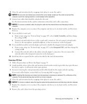
6 Place the card in the top of the card or filler bracket fits around the alignment guide. not fully seated card fully seated card bracket within slot alignment guide alignment bar bracket caught outside of slot 7 Before you close the card retention door, ensure that the card is fully seated in the slot. alignment guide alignment bar release tab card retention door 74 Removing and Installing Parts Ensure that : • The tops of all cards and filler brackets are flush with the alignment bar. • The notch in the connector and press down firmly.
6 Place the card in the top of the card or filler bracket fits around the alignment guide. not fully seated card fully seated card bracket within slot alignment guide alignment bar bracket caught outside of slot 7 Before you close the card retention door, ensure that the card is fully seated in the slot. alignment guide alignment bar release tab card retention door 74 Removing and Installing Parts Ensure that : • The tops of all cards and filler brackets are flush with the alignment bar. • The notch in the connector and press down firmly.
Owner's Manual
Page 75
... connect external audio devices to the microphone, speaker/headphone, or line-in connectors on the back panel. 12 If you need a filler bracket, contact Dell (see "Contacting Dell" on page 120). Do not connect the network cable to the integrated connector on page 107), select Audio Controller, and then change the setting... to maintain FCC certification of your computer. 4 Close the card retention door by snapping it into place to the sound card's connectors. Removing and Installing Parts 75
... connect external audio devices to the microphone, speaker/headphone, or line-in connectors on the back panel. 12 If you need a filler bracket, contact Dell (see "Contacting Dell" on page 120). Do not connect the network cable to the integrated connector on page 107), select Audio Controller, and then change the setting... to maintain FCC certification of your computer. 4 Close the card retention door by snapping it into place to the sound card's connectors. Removing and Installing Parts 75

