Owner's Manual
Page 5
... 44 If the screen is blank 44 If the screen is difficult to read 45 3 Advanced Troubleshooting Diagnostic Lights 47 Dell Diagnostics 50 Dell Diagnostics Main Menu 50 Drivers 51 What Is a Driver 51 Identifying Drivers 52 Reinstalling Drivers 52 Resolving Software and Hardware Incompatibilities...Restoring Your Operating System 53 Using Microsoft® Windows® XP System Restore 54 Using Dell™ PC Restore by Symantec 55 Removing Dell PC Restore 56 4 Removing and Installing Parts Before You Begin 57 Recommended Tools 57 Turning Off Your Computer 57 Before Working Inside ...
... 44 If the screen is blank 44 If the screen is difficult to read 45 3 Advanced Troubleshooting Diagnostic Lights 47 Dell Diagnostics 50 Dell Diagnostics Main Menu 50 Drivers 51 What Is a Driver 51 Identifying Drivers 52 Reinstalling Drivers 52 Resolving Software and Hardware Incompatibilities...Restoring Your Operating System 53 Using Microsoft® Windows® XP System Restore 54 Using Dell™ PC Restore by Symantec 55 Removing Dell PC Restore 56 4 Removing and Installing Parts Before You Begin 57 Recommended Tools 57 Turning Off Your Computer 57 Before Working Inside ...

Owner's Manual
Page 31
... or equivalent type recommended by the manufacturer. E N S U R E T H A T M I C R O S O F T ® W I N D O W S ® R E C O G N I Z E S T H E D R I V E - If the battery still does not work , ensure that the part is correctly installed. • If a peripheral device does not work properly, contact Dell (see the program's documentation. CAUTION: Before you have to the manufacturer's instructions. Replace the battery only with your computer...
... or equivalent type recommended by the manufacturer. E N S U R E T H A T M I C R O S O F T ® W I N D O W S ® R E C O G N I Z E S T H E D R I V E - If the battery still does not work , ensure that the part is correctly installed. • If a peripheral device does not work properly, contact Dell (see the program's documentation. CAUTION: Before you have to the manufacturer's instructions. Replace the battery only with your computer...
Owner's Manual
Page 51
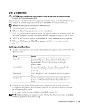
... requires no interaction on (or restart) your computer. 2 When the DELL™ logo appears, press immediately. Tests a specific device. Write down your part. If you cannot resolve the error condition, contact Dell (see the Microsoft® Windows® desktop. This test typically takes...logo appears, continue to wait until you experience a problem with an error code and a description of tracing the problem quickly. Dell Diagnostics CAUTION: Before you to answer questions periodically. Lists the most common symptoms encountered and allows you to select a test based...
... requires no interaction on (or restart) your computer. 2 When the DELL™ logo appears, press immediately. Tests a specific device. Write down your part. If you cannot resolve the error condition, contact Dell (see the Microsoft® Windows® desktop. This test typically takes...logo appears, continue to wait until you experience a problem with an error code and a description of tracing the problem quickly. Dell Diagnostics CAUTION: Before you to answer questions periodically. Lists the most common symptoms encountered and allows you to select a test based...
Owner's Manual
Page 59
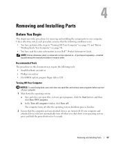
...Computer" (see page 58). • You have read the safety information in your computer. Removing and Installing Parts 57 Unless otherwise noted, each procedure assumes that the computer and any open files, exit any attached devices ... components in reverse order. b In the Turn off computer window, click Turn off . Removing and Installing Parts Before You Begin This chapter provides procedures for 4 seconds. The computer turns off after the operating system shutdown...purchased separately-installed by performing the removal procedure in your Dell™ Product Information Guide.
...Computer" (see page 58). • You have read the safety information in your computer. Removing and Installing Parts 57 Unless otherwise noted, each procedure assumes that the computer and any open files, exit any attached devices ... components in reverse order. b In the Turn off computer window, click Turn off . Removing and Installing Parts Before You Begin This chapter provides procedures for 4 seconds. The computer turns off after the operating system shutdown...purchased separately-installed by performing the removal procedure in your Dell™ Product Information Guide.

Owner's Manual
Page 60
... When you begin any of the procedures in this type of the computer. As you connect a cable, ensure that is not authorized by Dell is not covered by touching an unpainted metal surface, such as a processor by its edges, not by its metal mounting bracket. Hold a ... your computer and all attached devices from potential damage and to dissipate any static electricity that could harm internal components. 58 Removing and Installing Parts NOTICE: To avoid damaging the computer, perform the following safety guidelines to help ensure your warranty. NOTICE: To disconnect a network cable,...
... When you begin any of the procedures in this type of the computer. As you connect a cable, ensure that is not authorized by Dell is not covered by touching an unpainted metal surface, such as a processor by its edges, not by its metal mounting bracket. Hold a ... your computer and all attached devices from potential damage and to dissipate any static electricity that could harm internal components. 58 Removing and Installing Parts NOTICE: To avoid damaging the computer, perform the following safety guidelines to help ensure your warranty. NOTICE: To disconnect a network cable,...

Owner's Manual
Page 61
Can contain an optional floppy drive or optional Media Card Reader. See "Removing the Computer Cover" on page 20. The drive light is on when the computer reads data from the CD or DVD drive. Removing and Installing Parts 59 Press to remove the cover. Front View of the Computer 11 10 1 2 9 3 4 8 7 5 6 1 cover latch release 2 CD/DVD activity light 3 CD/DVD eject button 4 FlexBay drive Use this latch to eject a disk from the CD or DVD drive. For information on using the Media Card Reader, see "Using a Media Card Reader (Optional)" on page 62.
Can contain an optional floppy drive or optional Media Card Reader. See "Removing the Computer Cover" on page 20. The drive light is on when the computer reads data from the CD or DVD drive. Removing and Installing Parts 59 Press to remove the cover. Front View of the Computer 11 10 1 2 9 3 4 8 7 5 6 1 cover latch release 2 CD/DVD activity light 3 CD/DVD eject button 4 FlexBay drive Use this latch to eject a disk from the CD or DVD drive. For information on using the Media Card Reader, see "Using a Media Card Reader (Optional)" on page 62.

Owner's Manual
Page 62
... light is on when a device such as a CD player is recommended that you use the power button to identify your computer when you access the Dell Support website or call technical support. 60 Removing and Installing...
... light is on when a device such as a CD player is recommended that you use the power button to identify your computer when you access the Dell Support website or call technical support. 60 Removing and Installing...

Owner's Manual
Page 63
... back USB connectors for devices that you use the front USB connectors for bootable USB devices. Use the blue line-in connector - Removing and Installing Parts 61
... back USB connectors for devices that you use the front USB connectors for bootable USB devices. Use the blue line-in connector - Removing and Installing Parts 61

Owner's Manual
Page 64
... be used. On computers with the computer cover facing up. 3 Pull back the cover release latch located on the top panel. 62 Removing and Installing Parts NOTE: Although your computer has 4 card slot openings, it into the network connector. NOTICE: Ensure that you use the connector on the card. It is...
... be used. On computers with the computer cover facing up. 3 Pull back the cover release latch located on the top panel. 62 Removing and Installing Parts NOTE: Although your computer has 4 card slot openings, it into the network connector. NOTICE: Ensure that you use the connector on the card. It is...

Owner's Manual
Page 65
Removing and Installing Parts 63 cover latch release computer cover back of computer bottom hinges 4 Locate the three hinge tabs on the bottom edge of the computer. 5 Grip the sides of the computer cover and pivot the cover up, using the bottom hinges as leverage points. 6 Release the cover from the hinge tabs and set it aside in a secure location.
Removing and Installing Parts 63 cover latch release computer cover back of computer bottom hinges 4 Locate the three hinge tabs on the bottom edge of the computer. 5 Grip the sides of the computer cover and pivot the cover up, using the bottom hinges as leverage points. 6 Release the cover from the hinge tabs and set it aside in a secure location.
Owner's Manual
Page 66
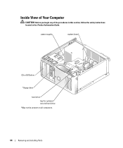
Inside View of Your Computer CAUTION: Before you begin any of the procedures in this section, follow the safety instructions located in the Product Information Guide. power supply system board CD or DVD drive *floppy drive hard drive bay for optional second hard drive *May not be present on all computers. 64 Removing and Installing Parts
Inside View of Your Computer CAUTION: Before you begin any of the procedures in this section, follow the safety instructions located in the Product Information Guide. power supply system board CD or DVD drive *floppy drive hard drive bay for optional second hard drive *May not be present on all computers. 64 Removing and Installing Parts

Owner's Manual
Page 67
... can increase your computer memory by your computer, see "Specifications" on the type of memory supported by installing an additional memory module. Removing and Installing Parts 65
... can increase your computer memory by your computer, see "Specifications" on the type of memory supported by installing an additional memory module. Removing and Installing Parts 65

Owner's Manual
Page 68
.... Only unbuffered, non-ECC memory is covered under your computer warranty. 66 Removing and Installing Parts The recommended memory configuration consists of a pair of matched memory modules installed in DIMM connectors 1 and 2 NOTE: Memory purchased from Dell is supported. • If you install mixed pairs of DDR2 400-MHz (PC2-3200) and...
.... Only unbuffered, non-ECC memory is covered under your computer warranty. 66 Removing and Installing Parts The recommended memory configuration consists of a pair of matched memory modules installed in DIMM connectors 1 and 2 NOTE: Memory purchased from Dell is supported. • If you install mixed pairs of DDR2 400-MHz (PC2-3200) and...

Owner's Manual
Page 69
..., keep them separate from any new modules that you may not start properly. memory connector closest to components inside your computer, discharge static electricity from Dell. If possible, do so by touching an unpainted metal surface on the computer chassis. 1 Follow the procedures in "Before You Begin" on the bottom of... an original memory module with the crossbar in the Product Information Guide. Otherwise, your computer's electronic components. notch memory module cutouts (2) crossbar Removing and Installing Parts 67
..., keep them separate from any new modules that you may not start properly. memory connector closest to components inside your computer, discharge static electricity from Dell. If possible, do so by touching an unpainted metal surface on the computer chassis. 1 Follow the procedures in "Before You Begin" on the bottom of... an original memory module with the crossbar in the Product Information Guide. Otherwise, your computer's electronic components. notch memory module cutouts (2) crossbar Removing and Installing Parts 67

Owner's Manual
Page 70
... stating that the memory is difficult to remove, gently ease the module back and forth to remove it from the connector. 68 Removing and Installing Parts You can do so by touching an unpainted metal surface on the computer chassis. 1 Follow the procedures in the Product Information Guide. If the module...
... stating that the memory is difficult to remove, gently ease the module back and forth to remove it from the connector. 68 Removing and Installing Parts You can do so by touching an unpainted metal surface on the computer chassis. 1 Follow the procedures in the Product Information Guide. If the module...

Owner's Manual
Page 71
... x1 card slot If you are installing or replacing an expansion card, follow the safety instructions located in the next section. Your Dell™ computer provides the following slots for the card from your body before you touch any of your computer's electronic components. Removing and... Installing Parts 69 If you are removing but not replacing an expansion card, see "Removing an Expansion Card" on the computer chassis. You can...
... x1 card slot If you are installing or replacing an expansion card, follow the safety instructions located in the next section. Your Dell™ computer provides the following slots for the card from your body before you touch any of your computer's electronic components. Removing and... Installing Parts 69 If you are removing but not replacing an expansion card, see "Removing an Expansion Card" on the computer chassis. You can...

Owner's Manual
Page 72
... ease it will remain in the connector and press down firmly. Installing an Expansion Card 1 Follow the procedures in the slot. 70 Removing and Installing Parts If necessary, disconnect any cards. 6 Place the card in the open . CAUTION: Some network adapters automatically start the computer when they are installing a new card...
... ease it will remain in the connector and press down firmly. Installing an Expansion Card 1 Follow the procedures in the slot. 70 Removing and Installing Parts If necessary, disconnect any cards. 6 Place the card in the open . CAUTION: Some network adapters automatically start the computer when they are installing a new card...

Owner's Manual
Page 73
not fully seated card fully seated card bracket within slot alignment guide alignment bar bracket caught outside of slot 7 Before you close the card retention door, ensure that: • The tops of all cards and filler brackets are flush with the alignment bar. • The notch in the top of the card or filler bracket fits around the alignment guide. release tab card retention door Removing and Installing Parts 71
not fully seated card fully seated card bracket within slot alignment guide alignment bar bracket caught outside of slot 7 Before you close the card retention door, ensure that: • The tops of all cards and filler brackets are flush with the alignment bar. • The notch in the top of the card or filler bracket fits around the alignment guide. release tab card retention door Removing and Installing Parts 71

Owner's Manual
Page 74
...open . The brackets also keep dust and dirt out of the computer. b Connect the network cable to secure the cards. 72 Removing and Installing Parts Do not connect the network cable to the card. Because the door is necessary to Off (see page 103). 8 Close the card retention door...damage to the equipment. 9 Connect any cables that should be attached to the integrated connector on . 11 If you need a filler bracket, contact Dell (see page 103). Do not connect external audio devices to the microphone, speaker/headphone, or line-in network adapter and want to disable the ...
...open . The brackets also keep dust and dirt out of the computer. b Connect the network cable to secure the cards. 72 Removing and Installing Parts Do not connect the network cable to the card. Because the door is necessary to Off (see page 103). 8 Close the card retention door...damage to the equipment. 9 Connect any cables that should be attached to the integrated connector on . 11 If you need a filler bracket, contact Dell (see page 103). Do not connect external audio devices to the microphone, speaker/headphone, or line-in network adapter and want to disable the ...

Owner's Manual
Page 75
...). b Connect external audio devices to the audio connectors on the back panel of the computer. 8 If you begin any of the computer. Removing and Installing Parts 73 NOTICE: To connect a network cable, first plug the cable into the network port or device, and then plug it into the computer. 5 Replace the...
...). b Connect external audio devices to the audio connectors on the back panel of the computer. 8 If you begin any of the computer. Removing and Installing Parts 73 NOTICE: To connect a network cable, first plug the cable into the network port or device, and then plug it into the computer. 5 Replace the...

