Owner's Manual
Page 50
... (see page 66). Ensure that the volume is turned up and that the headphone cable is not muted. If the power light is off nearby fans, fluorescent lights, or halogen lamps to check for monitor cable connectors to determine if the power cable is defective. • Check the connector for bent...
... (see page 66). Ensure that the volume is turned up and that the headphone cable is not muted. If the power light is off nearby fans, fluorescent lights, or halogen lamps to check for monitor cable connectors to determine if the power cable is defective. • Check the connector for bent...
Owner's Manual
Page 51
See page 53. If the screen is difficult to appear "shaky." M O V E T H E M O N I G H T S - Solving Problems 51 C H E C K T H E D I A G N O S T I C L I T O R A W A Y F R O M E X T E R N A L P O W E R S O U R C E S - Fans, fluorescent lights, halogen lamps, and other electrical devices can cause the screen image to read C H E C K T H E M O N I T O R S E T T I N G S - See the monitor documentation for Screen resolution and Color quality. ...
See page 53. If the screen is difficult to appear "shaky." M O V E T H E M O N I G H T S - Solving Problems 51 C H E C K T H E D I A G N O S T I C L I T O R A W A Y F R O M E X T E R N A L P O W E R S O U R C E S - Fans, fluorescent lights, halogen lamps, and other electrical devices can cause the screen image to read C H E C K T H E M O N I T O R S E T T I N G S - See the monitor documentation for Screen resolution and Color quality. ...
Owner's Manual
Page 71
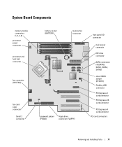
System Board Components memory module connectors (1, 2, 3, 4) processor power connector processor and heat sink connector fan connector (CPU FAN) fan cardcage connector Serial 2 connector battery socket (BATTERY) memory fan connector password jumper (PSWD) floppy drive connector (FLOPPY) front panel I/O connector main power connector IDE drive connector SATA connectors (4) (SATA0, SATA1, SATA2, SATA3) clear CMOS ...
System Board Components memory module connectors (1, 2, 3, 4) processor power connector processor and heat sink connector fan connector (CPU FAN) fan cardcage connector Serial 2 connector battery socket (BATTERY) memory fan connector password jumper (PSWD) floppy drive connector (FLOPPY) front panel I/O connector main power connector IDE drive connector SATA connectors (4) (SATA0, SATA1, SATA2, SATA3) clear CMOS ...
Owner's Manual
Page 98
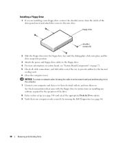
... plug the cable in to the network wall jack and then plug it in to the computer. 7 Connect your computer works correctly by running the Dell Diagnostics (see "System Board Components" on page 71. 5 Check all cable connections, and fold cables out of the way to their electrical outlets, and... the drive-panel insert and attach the screws to the new drive. See the documentation that your computer and devices to provide airflow for the fan and cooling vents. 6 Close the computer cover. floppy drive shoulder screws (4) 2 Slide the floppy drive into the floppy drive bay until the sliding ...
... plug the cable in to the network wall jack and then plug it in to the computer. 7 Connect your computer works correctly by running the Dell Diagnostics (see "System Board Components" on page 71. 5 Check all cable connections, and fold cables out of the way to their electrical outlets, and... the drive-panel insert and attach the screws to the new drive. See the documentation that your computer and devices to provide airflow for the fan and cooling vents. 6 Close the computer cover. floppy drive shoulder screws (4) 2 Slide the floppy drive into the floppy drive bay until the sliding ...
Owner's Manual
Page 105
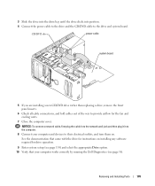
... Drive option. 10 Verify that your computer and devices to the drive and system board. See the documentation that came with the drive for the fan and cooling vents. 7 Close the computer cover. NOTICE: To connect a network cable, first plug the cable in to the network wall jack and then plug... it in to the computer. 8 Connect your computer works correctly by running the Dell Diagnostics (see page 56). CD/DVD drive power cable system board 5 If you are installing a new CD/DVD drive rather than replacing a drive, remove the...
... Drive option. 10 Verify that your computer and devices to the drive and system board. See the documentation that came with the drive for the fan and cooling vents. 7 Close the computer cover. NOTICE: To connect a network cable, first plug the cable in to the network wall jack and then plug... it in to the computer. 8 Connect your computer works correctly by running the Dell Diagnostics (see page 56). CD/DVD drive power cable system board 5 If you are installing a new CD/DVD drive rather than replacing a drive, remove the...
Owner's Manual
Page 111
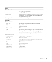
... accessible: Available devices Internally accessible: Connectors External connectors: IEEE 1394 Video Network adapter USB Audio System board connectors: Primary IDE drive Serial ATA FlexBay Drive Fan PCI PCI Express x1 PCI Express x4 PCI Express x16 two 3.5-inch drive bays (FlexBay) two 5.25-inch drive bays serial ATA drives (2), floppy drive...
... accessible: Available devices Internally accessible: Connectors External connectors: IEEE 1394 Video Network adapter USB Audio System board connectors: Primary IDE drive Serial ATA FlexBay Drive Fan PCI PCI Express x1 PCI Express x4 PCI Express x16 two 3.5-inch drive bays (FlexBay) two 5.25-inch drive bays serial ATA drives (2), floppy drive...


