Owner's Manual
Page 5
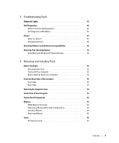
3 Troubleshooting Tools Diagnostic Lights 43 Dell Diagnostics 46 When to Use the Dell Diagnostics 46 Dell Diagnostics Main Menu 46 Drivers 47 What Is a Driver 47 Reinstalling Drivers 48 Resolving Software and Hardware Incompatibilities 49 Restoring Your Operating System 49 Using Microsoft Windows XP System Restore 49 4 Removing and Installing Parts Before You Begin 53...
3 Troubleshooting Tools Diagnostic Lights 43 Dell Diagnostics 46 When to Use the Dell Diagnostics 46 Dell Diagnostics Main Menu 46 Drivers 47 What Is a Driver 47 Reinstalling Drivers 48 Resolving Software and Hardware Incompatibilities 49 Restoring Your Operating System 49 Using Microsoft Windows XP System Restore 49 4 Removing and Installing Parts Before You Begin 53...

Owner's Manual
Page 27
...battery exploding if it is correctly installed. • If a peripheral device does not work properly, contact Dell (see the program's documentation. Replace the battery only with your computer: • If you begin ... I C R O S O F T ® W I N D O W S ® R E C O G N I Z E S T H E D R I V E - If the battery still does not work , ensure that the part is incorrectly installed. Solving Problems 27 Drive Problems CAUTION: Before you added or removed a part before the problem started, review the installation procedures and ensure that the device is not listed, perform a full...
...battery exploding if it is correctly installed. • If a peripheral device does not work properly, contact Dell (see the program's documentation. Replace the battery only with your computer: • If you begin ... I C R O S O F T ® W I N D O W S ® R E C O G N I Z E S T H E D R I V E - If the battery still does not work , ensure that the part is incorrectly installed. Solving Problems 27 Drive Problems CAUTION: Before you added or removed a part before the problem started, review the installation procedures and ensure that the device is not listed, perform a full...

Owner's Manual
Page 46
... of the problem you are having. 2 If a problem is encountered during a test, a message appears with your part. Run Express Test first to run (see page 46). If you cannot resolve the error condition, contact Dell (see the Microsoft® Windows® desktop. You can customize the tests you want to increase the...
... of the problem you are having. 2 If a problem is encountered during a test, a message appears with your part. Run Express Test first to run (see page 46). If you cannot resolve the error condition, contact Dell (see the Microsoft® Windows® desktop. You can customize the tests you want to increase the...

Owner's Manual
Page 53
... damage and to help ensure your operating system, press and hold the power button for removing and installing the components in your Dell™ Product Information Guide. • A component can be replaced or-if purchased separately-installed by performing the removal procedure in... reverse order. Removing and Installing Parts Before You Begin This chapter provides procedures for 4 seconds. Unless otherwise noted, each procedure assumes that the computer and any open files...
... damage and to help ensure your operating system, press and hold the power button for removing and installing the components in your Dell™ Product Information Guide. • A component can be replaced or-if purchased separately-installed by performing the removal procedure in... reverse order. Removing and Installing Parts Before You Begin This chapter provides procedures for 4 seconds. Unless otherwise noted, each procedure assumes that the computer and any open files...

Owner's Manual
Page 54
...electrical outlet before you pull connectors apart, keep them evenly aligned to servicing that could harm internal components. 54 Removing and Installing Parts CAUTION: To guard against electrical shock, always unplug your computer from their electrical outlets, and then press the power button to ... oriented and aligned. Hold a component such as the metal at the back of cable, press in the Product Information Guide. www.dell.com | support.dell.com CAUTION: Before you begin working inside your warranty. NOTICE: When you disconnect a cable, pull on its connector or on a...
...electrical outlet before you pull connectors apart, keep them evenly aligned to servicing that could harm internal components. 54 Removing and Installing Parts CAUTION: To guard against electrical shock, always unplug your computer from their electrical outlets, and then press the power button to ... oriented and aligned. Hold a component such as the metal at the back of cable, press in the Product Information Guide. www.dell.com | support.dell.com CAUTION: Before you begin working inside your warranty. NOTICE: When you disconnect a cable, pull on its connector or on a...

Owner's Manual
Page 55
For instructions on how to reattach the door, see page 59. 11 10 1 2 9 8 3 7 6 5 4 Removing and Installing Parts 55 NOTE: The front-panel door is removable; if you are using certain Flash Media or IEEE 1394, USB, or headphone connectors. Front and Back View of the Computer Front View NOTE: The front-panel door does not close when you remove it or accidentally knock it off its hinges, it snaps back in place.
For instructions on how to reattach the door, see page 59. 11 10 1 2 9 8 3 7 6 5 4 Removing and Installing Parts 55 NOTE: The front-panel door is removable; if you are using certain Flash Media or IEEE 1394, USB, or headphone connectors. Front and Back View of the Computer Front View NOTE: The front-panel door does not close when you remove it or accidentally knock it off its hinges, it snaps back in place.

Owner's Manual
Page 56
...Blinking green - This panel covers the CD/DVD drive, the media card reader, and the optional floppy drive. 56 Removing and Installing Parts The computer is recommended that you connect occasionally, such as external hard drives and other storage devices. It is in a power-saving ...an operating system shutdown. Use the green headphone connector to attach headphones and most kinds of speakers. For more information on the computer. www.dell.com | support.dell.com 1 CD/DVD drive eject button 2 CD/DVD drive-activity light 3 USB 2.0 connectors (2) 4 IEEE 1394 connector 5 power button...
...Blinking green - This panel covers the CD/DVD drive, the media card reader, and the optional floppy drive. 56 Removing and Installing Parts The computer is recommended that you connect occasionally, such as external hard drives and other storage devices. It is in a power-saving ...an operating system shutdown. Use the green headphone connector to attach headphones and most kinds of speakers. For more information on the computer. www.dell.com | support.dell.com 1 CD/DVD drive eject button 2 CD/DVD drive-activity light 3 USB 2.0 connectors (2) 4 IEEE 1394 connector 5 power button...

Owner's Manual
Page 57
Removing and Installing Parts 57 Back View 1 2 3 4 1 voltage selection switch (may not be available See the safety instructions in the Product on certain computers) Information Guide for more information. 2 power connector Insert the power cable. 3 back panel connectors Plug serial, USB, and other devices into the appropriate connector. 4 card slots Access connectors for any installed PCI and PCI Express cards.
Removing and Installing Parts 57 Back View 1 2 3 4 1 voltage selection switch (may not be available See the safety instructions in the Product on certain computers) Information Guide for more information. 2 power connector Insert the power cable. 3 back panel connectors Plug serial, USB, and other devices into the appropriate connector. 4 card slots Access connectors for any installed PCI and PCI Express cards.

Owner's Manual
Page 58
... attached. On computers with a network connector card, use Category 3 wiring, force the network speed to 10 Mbps to be in connector • Green - www.dell.com | support.dell.com 1 2 3 4 5 6 7 8 13 12 11 10 9 1 link integrity light 2 network adapter connector 3 network activity light 4 modem connector 5 surround sound connector 6 line-in a steady...computer. • Orange - A high volume of your network. A click indicates that you must use the connector on the card. 58 Removing and Installing Parts The computer is transmitting or receiving network data.
... attached. On computers with a network connector card, use Category 3 wiring, force the network speed to 10 Mbps to be in connector • Green - www.dell.com | support.dell.com 1 2 3 4 5 6 7 8 13 12 11 10 9 1 link integrity light 2 network adapter connector 3 network activity light 4 modem connector 5 surround sound connector 6 line-in a steady...computer. • Orange - A high volume of your network. A click indicates that you must use the connector on the card. 58 Removing and Installing Parts The computer is transmitting or receiving network data.

Owner's Manual
Page 59
... voice or musical input into the VGA connector on the computer. Attach high-speed serial multimedia devices, such as printers and keyboards. Removing and Installing Parts 59 Systems not using subwoofers can shunt the LFE information to provide extremely low bass extension. Use the pink and silver connector to support the...
... voice or musical input into the VGA connector on the computer. Attach high-speed serial multimedia devices, such as printers and keyboards. Removing and Installing Parts 59 Systems not using subwoofers can shunt the LFE information to provide extremely low bass extension. Use the pink and silver connector to support the...

Owner's Manual
Page 60
www.dell.com | support.dell.com NOTICE: Ensure that you are working on a level, protected surface to avoid scratching either the computer or the surface on which it aside in a secure location. 60 Removing and Installing Parts security cable slot cover release latch computer cover 7 Locate the two hinge tabs on the bottom edge...
www.dell.com | support.dell.com NOTICE: Ensure that you are working on a level, protected surface to avoid scratching either the computer or the surface on which it aside in a secure location. 60 Removing and Installing Parts security cable slot cover release latch computer cover 7 Locate the two hinge tabs on the bottom edge...

Owner's Manual
Page 61
CAUTION: To guard against electrical shock, always unplug your computer from the electrical outlet before opening the cover. CD/DVD drive drive release latch power supply and fan hard drive front-panel door power button system board heat sink and blower assembly Removing and Installing Parts 61 Inside View of Your Computer CAUTION: Before you begin any of the procedures in this section, follow the safety instructions in the Product Information Guide.
CAUTION: To guard against electrical shock, always unplug your computer from the electrical outlet before opening the cover. CD/DVD drive drive release latch power supply and fan hard drive front-panel door power button system board heat sink and blower assembly Removing and Installing Parts 61 Inside View of Your Computer CAUTION: Before you begin any of the procedures in this section, follow the safety instructions in the Product Information Guide.

Owner's Manual
Page 63
... indicated on the module to operate, but with a slight reduction in matched pairs, the computer will continue to determine the module's capacity. Removing and Installing Parts 63 See the label on the system board. Your computer supports DDR2 memory. The recommended memory configurations are not installed in performance.
... indicated on the module to operate, but with a slight reduction in matched pairs, the computer will continue to determine the module's capacity. Removing and Installing Parts 63 See the label on the system board. Your computer supports DDR2 memory. The recommended memory configurations are not installed in performance.

Owner's Manual
Page 64
... to components inside of the computer. 3 Press out the securing clip at each end of the memory module connector. 64 Removing and Installing Parts You can only use two 2-GB DIMMs. Current operating systems, such as Microsoft® Windows® XP, can do not pair an ... and 4. NOTICE: To prevent static damage to the operating system is on the bottom of the inside your computer, discharge static electricity from Dell is covered under your computer's electronic components. If possible, do so by computer memory. Certain components within the computer require address space in ...
... to components inside of the computer. 3 Press out the securing clip at each end of the memory module connector. 64 Removing and Installing Parts You can only use two 2-GB DIMMs. Current operating systems, such as Microsoft® Windows® XP, can do not pair an ... and 4. NOTICE: To prevent static damage to the operating system is on the bottom of the inside your computer, discharge static electricity from Dell is covered under your computer's electronic components. If possible, do so by computer memory. Certain components within the computer require address space in ...

Owner's Manual
Page 65
Removing and Installing Parts 65 memory connector closest to each end of the module. 5 Insert the module into the connector until the module snaps into the cutouts at each end of the module with the crossbar in the connector. If you apply equal force to processor securing clips (2) connector 4 Align the notch on the bottom of the module. notch memory module cutouts (2) crossbar NOTICE: To avoid damage to the memory module, press the module straight down into the connector while you insert the module correctly, the securing clips snap into position.
Removing and Installing Parts 65 memory connector closest to each end of the module. 5 Insert the module into the connector until the module snaps into the cutouts at each end of the module with the crossbar in the connector. If you apply equal force to processor securing clips (2) connector 4 Align the notch on the bottom of the module. notch memory module cutouts (2) crossbar NOTICE: To avoid damage to the memory module, press the module straight down into the connector while you insert the module correctly, the securing clips snap into position.

Owner's Manual
Page 66
... from your computer, discharge static electricity from the connector. You can do so by touching an unpainted metal surface on the computer chassis. Your Dell™ computer provides the following slots for PCI Express cards: • One PCI Express x16 card slot • One PCI Express x1 card... slot NOTE: The slots for the PCI Express x16 and PCI Express x1 cards are half-height slots. 66 Removing and Installing Parts Removing Memory CAUTION: Before you touch any of the procedures in this section, follow the safety instructions located in the Product Information Guide. ...
... from your computer, discharge static electricity from the connector. You can do so by touching an unpainted metal surface on the computer chassis. Your Dell™ computer provides the following slots for PCI Express cards: • One PCI Express x16 card slot • One PCI Express x1 card... slot NOTE: The slots for the PCI Express x16 and PCI Express x1 cards are half-height slots. 66 Removing and Installing Parts Removing Memory CAUTION: Before you touch any of the procedures in this section, follow the safety instructions located in the Product Information Guide. ...
Owner's Manual
Page 67
... the door open position. 3 If you are installing a new card, remove the filler bracket to the card. If necessary, disconnect any cards. Removing and Installing Parts 67 To guard against electrical shock, be sure to a network. Then continue with the card for information on configuring the card, making internal connections, or...
... the door open position. 3 If you are installing a new card, remove the filler bracket to the card. If necessary, disconnect any cards. Removing and Installing Parts 67 To guard against electrical shock, be sure to a network. Then continue with the card for information on configuring the card, making internal connections, or...

Owner's Manual
Page 68
Ensure that the card is fully seated in the slot. 68 Removing and Installing Parts CAUTION: Some network adapters automatically start the computer when they are installing the card into the x16 card connector, position the card so the securing ... its electrical outlet before installing any cards. 8 If you are connected to unplug your computer. To guard against electrical shock, be sure to a network. www.dell.com | support.dell.com 6 Place the card in the connector and press down firmly.
Ensure that the card is fully seated in the slot. 68 Removing and Installing Parts CAUTION: Some network adapters automatically start the computer when they are installing the card into the x16 card connector, position the card so the securing ... its electrical outlet before installing any cards. 8 If you are connected to unplug your computer. To guard against electrical shock, be sure to a network. www.dell.com | support.dell.com 6 Place the card in the connector and press down firmly.

Owner's Manual
Page 69
Removing and Installing Parts 69 card not fully seated card fully seated bracket within slot bracket caught outside of slot 10 Before you close the card retention door, ensure that: • The tops of all cards and filler brackets are flush with the alignment bar. • The notch in the top of the card or filler bracket fits around the alignment guide.
Removing and Installing Parts 69 card not fully seated card fully seated bracket within slot bracket caught outside of slot 10 Before you close the card retention door, ensure that: • The tops of all cards and filler brackets are flush with the alignment bar. • The notch in the top of the card or filler bracket fits around the alignment guide.
Owner's Manual
Page 70
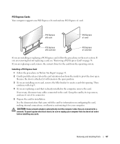
www.dell.com | support.dell.com 11 Close the card retention door by its top corners, and then ease it into place to electrical outlets, and then turn them on ... cables connected to the card. 3 Gently pull back the securing tab, grasp the card by snapping it out of its connector. 70 Removing and Installing Parts Cables routed over or behind the cards. NOTICE: To connect a network cable, first plug the cable into the network device and then plug it into...
www.dell.com | support.dell.com 11 Close the card retention door by its top corners, and then ease it into place to electrical outlets, and then turn them on ... cables connected to the card. 3 Gently pull back the securing tab, grasp the card by snapping it out of its connector. 70 Removing and Installing Parts Cables routed over or behind the cards. NOTICE: To connect a network cable, first plug the cable into the network device and then plug it into...

