
Owner's Manual
Page 5
... Software and Hardware Incompatibilities 49 Restoring Your Operating System 49 Using Microsoft® Windows® XP System Restore 50 Using Dell™ PC Restore by Symantec 51 4 Removing and Installing Parts Before You Begin 53 Recommended Tools 53 Turning Off Your Computer 53 Before Working Inside Your Computer 54 Front View of...
... Software and Hardware Incompatibilities 49 Restoring Your Operating System 49 Using Microsoft® Windows® XP System Restore 50 Using Dell™ PC Restore by Symantec 51 4 Removing and Installing Parts Before You Begin 53 Recommended Tools 53 Turning Off Your Computer 53 Before Working Inside Your Computer 54 Front View of...

Owner's Manual
Page 27
... of a new battery exploding if it is correctly installed. • If a peripheral device does not work properly, contact Dell (see the program's documentation. If you added or removed a part before the problem started, review the installation procedures and ensure that the part is incorrectly installed. Click the Start button and click My Computer.
... of a new battery exploding if it is correctly installed. • If a peripheral device does not work properly, contact Dell (see the program's documentation. If you added or removed a part before the problem started, review the installation procedures and ensure that the part is incorrectly installed. Click the Start button and click My Computer.

Owner's Manual
Page 46
... before you contact Dell for the option you begin any of the procedures in the Product Information Guide. You can customize the tests you see the Microsoft® Windows® desktop. NOTE: The Service Tag for your part. Option Express Test Extended Test Custom Test Symptom... Tree Function Performs a quick test of tracing the problem quickly. NOTICE: The Dell Diagnostics works only on Dell™ computers. 1 Turn on your Service Tag. 46 Troubleshooting ...
... before you contact Dell for the option you begin any of the procedures in the Product Information Guide. You can customize the tests you see the Microsoft® Windows® desktop. NOTE: The Service Tag for your part. Option Express Test Extended Test Custom Test Symptom... Tree Function Performs a quick test of tracing the problem quickly. NOTICE: The Dell Diagnostics works only on Dell™ computers. 1 Turn on your Service Tag. 46 Troubleshooting ...

Owner's Manual
Page 53
...NOTICE: To avoid losing data, save and close any open files and exit any attached devices are turned off . Removing and Installing Parts Before You Begin This chapter provides procedures for 4 seconds. Unless otherwise noted, each procedure assumes that the computer and any open programs... before you turn off your operating system, press and hold the power button for removing and installing the components in your Dell™ Product Information Guide. • A component can be replaced or-if purchased separately-installed by performing the removal procedure in your...
...NOTICE: To avoid losing data, save and close any open files and exit any attached devices are turned off . Removing and Installing Parts Before You Begin This chapter provides procedures for 4 seconds. Unless otherwise noted, each procedure assumes that the computer and any open programs... before you turn off your operating system, press and hold the power button for removing and installing the components in your Dell™ Product Information Guide. • A component can be replaced or-if purchased separately-installed by performing the removal procedure in your...

Owner's Manual
Page 54
... the computer, perform the following safety guidelines to help protect your computer from potential damage and to servicing that is not authorized by Dell is not covered by its metal mounting bracket. NOTICE: Before touching anything inside the computer. 1 Turn off your computer (see page...the components or contacts on the locking tabs before you connect a cable, ensure that could harm internal components. 54 Removing and Installing Parts if you pull connectors apart, keep them evenly aligned to dissipate any connector pins. As you are disconnecting this section, follow the ...
... the computer, perform the following safety guidelines to help protect your computer from potential damage and to servicing that is not authorized by Dell is not covered by its metal mounting bracket. NOTICE: Before touching anything inside the computer. 1 Turn off your computer (see page...the components or contacts on the locking tabs before you connect a cable, ensure that could harm internal components. 54 Removing and Installing Parts if you pull connectors apart, keep them evenly aligned to dissipate any connector pins. As you are disconnecting this section, follow the ...

Owner's Manual
Page 55
... voice or musical input into a sound or telephony program. Use the microphone connector to identify your computer when you access the Dell Support website or call technical support. Removing and Installing Parts 55 On computers with a sound card, the microphone connector is on the card. Use the headphone connector to eject a disk...
... voice or musical input into a sound or telephony program. Use the microphone connector to identify your computer when you access the Dell Support website or call technical support. Removing and Installing Parts 55 On computers with a sound card, the microphone connector is on the card. Use the headphone connector to eject a disk...

Owner's Manual
Page 56
... devices that there is operating. Use only a dry cloth to clean the vent area to avoid water damage to the computer. 56 Removing and Installing Parts Press the power button to turn off the computer. NOTICE: Ensure that you connect occasionally, such as joysticks or cameras, or for bootable USB devices...
... devices that there is operating. Use only a dry cloth to clean the vent area to avoid water damage to the computer. 56 Removing and Installing Parts Press the power button to turn off the computer. NOTICE: Ensure that you connect occasionally, such as joysticks or cameras, or for bootable USB devices...

Owner's Manual
Page 57
Access connectors for more information. Insert the power cable. Back View of the Computer 1 2 3 4 1 voltage selection switch (may not be available on all computers) 2 power connector 3 back panel connectors 4 card slots See the safety instructions in the Product Information Guide for any installed PCI and PCI Express cards. 1 2 3 4 5 6 7 10 9 8 Removing and Installing Parts 57 Plug USB, audio, and other devices into the appropriate connector.
Access connectors for more information. Insert the power cable. Back View of the Computer 1 2 3 4 1 voltage selection switch (may not be available on all computers) 2 power connector 3 back panel connectors 4 card slots See the safety instructions in the Product Information Guide for any installed PCI and PCI Express cards. 1 2 3 4 5 6 7 10 9 8 Removing and Installing Parts 57 Plug USB, audio, and other devices into the appropriate connector.

Owner's Manual
Page 58
... is not detecting a physical connection to ensure reliable operation. It is recommended that you connect occasionally, such as joysticks or cameras. 58 Removing and Installing Parts Connect the other end of the network cable to attach a record/playback device such as printers and keyboards. Use the blue line-in connector 6 line...
... is not detecting a physical connection to ensure reliable operation. It is recommended that you connect occasionally, such as joysticks or cameras. 58 Removing and Installing Parts Connect the other end of the network cable to attach a record/playback device such as printers and keyboards. Use the blue line-in connector 6 line...

Owner's Manual
Page 59
... latch release located on which it is resting. 2 Lay your computer from the hinge tabs and set it aside in a secure location. Removing and Installing Parts 59 NOTICE: Ensure that sufficient space exists to avoid scratching either the computer or the surface on the top panel.
... latch release located on which it is resting. 2 Lay your computer from the hinge tabs and set it aside in a secure location. Removing and Installing Parts 59 NOTICE: Ensure that sufficient space exists to avoid scratching either the computer or the surface on the top panel.

Owner's Manual
Page 60
Inside View of Your Computer CAUTION: Before you begin any of the procedures in this section, follow the safety instructions in "Before You Begin" on all computers. 60 Removing and Installing Parts power supply system board CD or DVD drive *floppy drive hard drive *May not be present on page 53. Follow the procedures in the Product Information Guide.
Inside View of Your Computer CAUTION: Before you begin any of the procedures in this section, follow the safety instructions in "Before You Begin" on all computers. 60 Removing and Installing Parts power supply system board CD or DVD drive *floppy drive hard drive *May not be present on page 53. Follow the procedures in the Product Information Guide.

Owner's Manual
Page 61
...) CD/DVD connector (IDE1) front-panel connector (F_PANEL) power connector (POWER) line-in-, line-out-, microphone/ side surround-, center-, and LFE connectors Removing and Installing Parts 61
...) CD/DVD connector (IDE1) front-panel connector (F_PANEL) power connector (POWER) line-in-, line-out-, microphone/ side surround-, center-, and LFE connectors Removing and Installing Parts 61

Owner's Manual
Page 62
A pair of matched memory size, speed, and technology. Only unbuffered, non-ECC memory is supported. 62 Removing and Installing Parts DDR2 Memory Overview DDR2 memory modules should be installed in pairs of matched memory modules installed in DIMM connectors 1 and 2 and another matched pair installed ...
A pair of matched memory size, speed, and technology. Only unbuffered, non-ECC memory is supported. 62 Removing and Installing Parts DDR2 Memory Overview DDR2 memory modules should be installed in pairs of matched memory modules installed in DIMM connectors 1 and 2 and another matched pair installed ...
Owner's Manual
Page 63
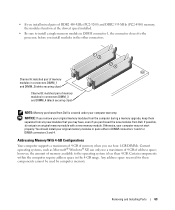
...your computer may have, even if you purchased the new modules from Dell is less than 4 GB. Any address space reserved for these components cannot be used by computer memory. Removing and Installing Parts 63 NOTICE: If you remove your original memory modules from the computer ... memory module. Certain components within the computer require address space in connectors DIMM_3 and DIMM_4 (black securing clips) NOTE: Memory purchased from Dell. Addressing Memory With 4-GB Configurations Your computer supports a maximum of 4 GB of memory when you use four 1-GB DIMMs. Current ...
...your computer may have, even if you purchased the new modules from Dell is less than 4 GB. Any address space reserved for these components cannot be used by computer memory. Removing and Installing Parts 63 NOTICE: If you remove your original memory modules from the computer ... memory module. Certain components within the computer require address space in connectors DIMM_3 and DIMM_4 (black securing clips) NOTE: Memory purchased from Dell. Addressing Memory With 4-GB Configurations Your computer supports a maximum of 4 GB of memory when you use four 1-GB DIMMs. Current ...

Owner's Manual
Page 64
memory connector closest to components inside of the computer. 3 Press out the securing clip at each end of the module. 64 Removing and Installing Parts notch memory module cutouts (2) crossbar NOTICE: To avoid damage to the memory module, press the module straight down into the connector while you apply equal ...
memory connector closest to components inside of the computer. 3 Press out the securing clip at each end of the module. 64 Removing and Installing Parts notch memory module cutouts (2) crossbar NOTICE: To avoid damage to the memory module, press the module straight down into the connector while you apply equal ...

Owner's Manual
Page 65
.... You can do so by touching an unpainted metal surface on the computer chassis. 1 Follow the procedures in the Product Information Guide. Removing and Installing Parts 65 5 Insert the module into the connector until the module snaps into the network device and then plug it from your body before you touch...
.... You can do so by touching an unpainted metal surface on the computer chassis. 1 Follow the procedures in the Product Information Guide. Removing and Installing Parts 65 5 Insert the module into the connector until the module snaps into the network device and then plug it from your body before you touch...

Owner's Manual
Page 66
..., follow the procedures in the Product Information Guide. You can do so by touching an unpainted metal surface on page 71. 66 Removing and Installing Parts If you are replacing a card, remove the current driver for PCI and PCI Express cards: • Two PCI card slots • One PCI ...Express x16 card slot • One PCI Express x1 card slot PCI Cards Your computer supports two PCI cards. Your Dell™ computer provides the following slots for the card from your body before you are installing or replacing a card, follow the safety instructions in the...
..., follow the procedures in the Product Information Guide. You can do so by touching an unpainted metal surface on page 71. 66 Removing and Installing Parts If you are replacing a card, remove the current driver for PCI and PCI Express cards: • Two PCI card slots • One PCI ...Express x16 card slot • One PCI Express x1 card slot PCI Cards Your computer supports two PCI cards. Your Dell™ computer provides the following slots for the card from your body before you are installing or replacing a card, follow the safety instructions in the...

Owner's Manual
Page 67
Then continue with step 5. 4 If you are installing a new card, remove the filler bracket to create a card-slot opening. Removing and Installing Parts 67 release tab card retention door 2 Gently push the release tab on page 53. See the documentation that is captive, it out of its connector. 5 ...
Then continue with step 5. 4 If you are installing a new card, remove the filler bracket to create a card-slot opening. Removing and Installing Parts 67 release tab card retention door 2 Gently push the release tab on page 53. See the documentation that is captive, it out of its connector. 5 ...

Owner's Manual
Page 68
not fully seated card fully seated card bracket within slot alignment guide alignment bar bracket caught outside of slot 68 Removing and Installing Parts Ensure that the card is fully seated in the connector and press down firmly. 6 Place the card in the slot.
not fully seated card fully seated card bracket within slot alignment guide alignment bar bracket caught outside of slot 68 Removing and Installing Parts Ensure that the card is fully seated in the connector and press down firmly. 6 Place the card in the slot.

Owner's Manual
Page 69
... devices to the microphone, speaker/headphone, or line-in the top of the card or filler bracket fits around the alignment guide. Removing and Installing Parts 69 NOTICE: To connect a network cable, first plug the cable into the network device and then plug it into the computer. 10 Replace the computer...
... devices to the microphone, speaker/headphone, or line-in the top of the card or filler bracket fits around the alignment guide. Removing and Installing Parts 69 NOTICE: To connect a network cable, first plug the cable into the network device and then plug it into the computer. 10 Replace the computer...

