

Service Manual
Page 1
Dell Latitude C600/C500 Series Service Manual Dell™ Latitude™ C600/C500 Series Service Manual Before You Begin Preparing to avoid the problem. NOTICE: A NOTICE indicates either potential damage to hardware or loss of data and tells you how to ... Bay Latch Assemblies Notes, Notices, and Cautions NOTE: A NOTE indicates important information that helps you make better use of 2) [2/28/2004 7:53:17 AM] file:///F|/Service%20Manuals/Dell/Latitude/c500-600/index.htm (1 of your computer.
Dell Latitude C600/C500 Series Service Manual Dell™ Latitude™ C600/C500 Series Service Manual Before You Begin Preparing to avoid the problem. NOTICE: A NOTICE indicates either potential damage to hardware or loss of data and tells you how to ... Bay Latch Assemblies Notes, Notices, and Cautions NOTE: A NOTE indicates important information that helps you make better use of 2) [2/28/2004 7:53:17 AM] file:///F|/Service%20Manuals/Dell/Latitude/c500-600/index.htm (1 of your computer.

Service Manual
Page 2
Disconnect the computer from the electrical outlet. 6. Before You Begin : Dell Latitude C600/C500 Series Service Manual Back to Contents Page Before You Begin Dell™ Latitude™ C600/C500 Series Service Manual Preparing to Work Inside the Computer Recommended Tools Screw Identification Preparing to -disk or hibernate mode. NOTE: Make sure the computer is turned off the ...
Disconnect the computer from the electrical outlet. 6. Before You Begin : Dell Latitude C600/C500 Series Service Manual Back to Contents Page Before You Begin Dell™ Latitude™ C600/C500 Series Service Manual Preparing to Work Inside the Computer Recommended Tools Screw Identification Preparing to -disk or hibernate mode. NOTE: Make sure the computer is turned off the ...

Service Manual
Page 3
... remove the main battery and secondary battery (if present) before you work surface. Before You Begin : Dell Latitude C600/C500 Series Service Manual 7. Close the display and turn the computer upside down on a card. Remove any installed device in this manual require the following tools: q #1 magnetized Phillips screwdriver q Small flat-blade screwdriver q Small plastic scribe q Microprocessor...
... remove the main battery and secondary battery (if present) before you work surface. Before You Begin : Dell Latitude C600/C500 Series Service Manual 7. Close the display and turn the computer upside down on a card. Remove any installed device in this manual require the following tools: q #1 magnetized Phillips screwdriver q Small flat-blade screwdriver q Small plastic scribe q Microprocessor...

Service Manual
Page 4
Before You Begin : Dell Latitude C600/C500 Series Service Manual Screw Identification When you are removing and replacing components, photocopy the placemat as a tool to lay out and keep track of screws and the sizes. The placemat provides the number of the component screws. Screw Identification file:///F|/Service%20Manuals/Dell/Latitude/c500-600/begin.htm (3 of 6) [2/28/2004 7:53:27 AM]
Before You Begin : Dell Latitude C600/C500 Series Service Manual Screw Identification When you are removing and replacing components, photocopy the placemat as a tool to lay out and keep track of screws and the sizes. The placemat provides the number of the component screws. Screw Identification file:///F|/Service%20Manuals/Dell/Latitude/c500-600/begin.htm (3 of 6) [2/28/2004 7:53:27 AM]

Service Manual
Page 5
Screw Placement Hard Drive Door Security: (1 each) Keyboard to Bottom Case Assembly: (5 each) Display Assembly Bezel: (6 each) Display Assembly Hinge Bracket to Bottom Case Assembly: (5 each) Rubber Screw Covers (6 each) file:///F|/Service%20Manuals/Dell/Latitude/c500-600/begin.htm (4 of the correct diameter and length. Before You Begin : Dell Latitude C600/C500 Series Service Manual NOTICE: When reinstalling a screw, you must use a screw of 6) [2/28/2004 7:53:27 AM] Make sure that the screw is properly aligned with its corresponding hole, and avoid overtightening.
Screw Placement Hard Drive Door Security: (1 each) Keyboard to Bottom Case Assembly: (5 each) Display Assembly Bezel: (6 each) Display Assembly Hinge Bracket to Bottom Case Assembly: (5 each) Rubber Screw Covers (6 each) file:///F|/Service%20Manuals/Dell/Latitude/c500-600/begin.htm (4 of the correct diameter and length. Before You Begin : Dell Latitude C600/C500 Series Service Manual NOTICE: When reinstalling a screw, you must use a screw of 6) [2/28/2004 7:53:27 AM] Make sure that the screw is properly aligned with its corresponding hole, and avoid overtightening.

Service Manual
Page 6
Before You Begin : Dell Latitude C600/C500 Series Service Manual Display Assembly and Flex Cable Retention Bracket to Top Cover: (5 each) Display Assembly EMI Shield Bracket: (2 each) Palmrest to Bottom Case Assembly: (5 each) (3 each) Hybrid Cooling Fan: (2 each) (1 each) System Board to Bottom Case Assembly: Display Panel to Support Bracket: (10 each) (12.1-inch display panel only) (4 each) file:///F|/Service%20Manuals/Dell/Latitude/c500-600/begin.htm (5 of 6) [2/28/2004 7:53:27 AM]
Before You Begin : Dell Latitude C600/C500 Series Service Manual Display Assembly and Flex Cable Retention Bracket to Top Cover: (5 each) Display Assembly EMI Shield Bracket: (2 each) Palmrest to Bottom Case Assembly: (5 each) (3 each) Hybrid Cooling Fan: (2 each) (1 each) System Board to Bottom Case Assembly: Display Panel to Support Bracket: (10 each) (12.1-inch display panel only) (4 each) file:///F|/Service%20Manuals/Dell/Latitude/c500-600/begin.htm (5 of 6) [2/28/2004 7:53:27 AM]
Service Manual
Page 8
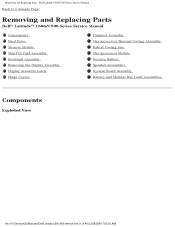
Removing and Replacing Parts : Dell Latitude C600/C500 Series Service Manual Back to Contents Page Removing and Replacing Parts Dell™ Latitude™ C600/C500 Series Service Manual Components Hard Drive Memory Module Mini-PCI Card Assembly Keyboard Assembly Removing the Display Assembly Display Assembly Latch Hinge Covers Palmrest Assembly Microprocessor Thermal Cooling ...
Removing and Replacing Parts : Dell Latitude C600/C500 Series Service Manual Back to Contents Page Removing and Replacing Parts Dell™ Latitude™ C600/C500 Series Service Manual Components Hard Drive Memory Module Mini-PCI Card Assembly Keyboard Assembly Removing the Display Assembly Display Assembly Latch Hinge Covers Palmrest Assembly Microprocessor Thermal Cooling ...

Service Manual
Page 9
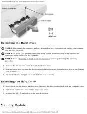
... shock. Hard Drive file:///F|/Service%20Manuals/Dell/Latitude/c500-600/remove.htm (2 of the hard drive case), and avoid dropping it. Handle the assembly by performing the removal procedure in this manual assumes that is not authorized by your system. Removing and Replacing Parts : Dell Latitude C600/C500 Series Service Manual NOTICE: Only a certified service technician should perform repairs on...
... shock. Hard Drive file:///F|/Service%20Manuals/Dell/Latitude/c500-600/remove.htm (2 of the hard drive case), and avoid dropping it. Handle the assembly by performing the removal procedure in this manual assumes that is not authorized by your system. Removing and Replacing Parts : Dell Latitude C600/C500 Series Service Manual NOTICE: Only a certified service technician should perform repairs on...
Service Manual
Page 10
... 2. Push down on the computer. Replace the M3 x 5-mm screw in the bottom case assembly. 3. Memory Module file:///F|/Service%20Manuals/Dell/Latitude/c500-600/remove.htm (3 of the bottom case assembly. NOTICE: To avoid ESD, ground yourself by using a wrist grounding strap... from electrical outlets, and remove any installed batteries. Gently push the hard drive into place. 3. Removing and Replacing Parts : Dell Latitude C600/C500 Series Service Manual Removing the Hard Drive NOTICE: Disconnect the computer and any attached devices from the hard drive door. 2. NOTICE: Read "Preparing...
... 2. Push down on the computer. Replace the M3 x 5-mm screw in the bottom case assembly. 3. Memory Module file:///F|/Service%20Manuals/Dell/Latitude/c500-600/remove.htm (3 of the bottom case assembly. NOTICE: To avoid ESD, ground yourself by using a wrist grounding strap... from electrical outlets, and remove any installed batteries. Gently push the hard drive into place. 3. Removing and Replacing Parts : Dell Latitude C600/C500 Series Service Manual Removing the Hard Drive NOTICE: Disconnect the computer and any attached devices from the hard drive door. 2. NOTICE: Read "Preparing...

Service Manual
Page 11
...NOTE: The screw labeled with the "circle K" in the middle of 40) [2/28/2004 7:53:33 AM] Memory Modules file:///F|/Service%20Manuals/Dell/Latitude/c500-600/remove.htm (4 of the memory module cover secures the keyboard assembly and does not secure the memory module cover. Remove ...b. Place your finger under the cover at the indentation and lift and slide the cover open. Removing and Replacing Parts : Dell Latitude C600/C500 Series Service Manual Memory Module Cover Removing the Memory Module Cover NOTICE: Disconnect the computer and any attached devices from electrical outlets, and remove ...
...NOTE: The screw labeled with the "circle K" in the middle of 40) [2/28/2004 7:53:33 AM] Memory Modules file:///F|/Service%20Manuals/Dell/Latitude/c500-600/remove.htm (4 of the memory module cover secures the keyboard assembly and does not secure the memory module cover. Remove ...b. Place your finger under the cover at the indentation and lift and slide the cover open. Removing and Replacing Parts : Dell Latitude C600/C500 Series Service Manual Memory Module Cover Removing the Memory Module Cover NOTICE: Disconnect the computer and any attached devices from electrical outlets, and remove ...

Service Manual
Page 12
Removing and Replacing Parts : Dell Latitude C600/C500 Series Service Manual Removing the Memory Modules NOTICE: Disconnect the computer and any installed batteries. NOTICE: Read "Preparing to disengage from the socket. Lift the memory module out ... pop up slightly. 3. NOTICE: To avoid ESD, ground yourself by using a wrist grounding strap or by touching an unpainted metal surface on the computer. file:///F|/Service%20Manuals/Dell/Latitude/c500-600/remove.htm (5 of 40) [2/28/2004 7:53:33 AM]
Removing and Replacing Parts : Dell Latitude C600/C500 Series Service Manual Removing the Memory Modules NOTICE: Disconnect the computer and any installed batteries. NOTICE: Read "Preparing to disengage from the socket. Lift the memory module out ... pop up slightly. 3. NOTICE: To avoid ESD, ground yourself by using a wrist grounding strap or by touching an unpainted metal surface on the computer. file:///F|/Service%20Manuals/Dell/Latitude/c500-600/remove.htm (5 of 40) [2/28/2004 7:53:33 AM]

Service Manual
Page 13
...-PCI Card Assembly Using Interface Cables Mini PCI Wireless NIC Assembly Using Antenna Cable file:///F|/Service%20Manuals/Dell/Latitude/c500-600/remove.htm (6 of a modem, a NIC, a modem and NIC combination, or a wireless NIC. Removing and Replacing Parts : Dell Latitude C600/C500 Series Service Manual NOTE: Memory modules are keyed, or designed to fit into their sockets, in the...
...-PCI Card Assembly Using Interface Cables Mini PCI Wireless NIC Assembly Using Antenna Cable file:///F|/Service%20Manuals/Dell/Latitude/c500-600/remove.htm (6 of a modem, a NIC, a modem and NIC combination, or a wireless NIC. Removing and Replacing Parts : Dell Latitude C600/C500 Series Service Manual NOTE: Memory modules are keyed, or designed to fit into their sockets, in the...

Service Manual
Page 14
...: To avoid ESD, ground yourself by using a wrist grounding strap or by touching an unpainted metal surface on the computer. Removing and Replacing Parts : Dell Latitude C600/C500 Series Service Manual Removing the Mini-PCI Card Assembly NOTICE: Disconnect the computer and any attached devices from its socket, spread apart the metal securing tabs until...
...: To avoid ESD, ground yourself by using a wrist grounding strap or by touching an unpainted metal surface on the computer. Removing and Replacing Parts : Dell Latitude C600/C500 Series Service Manual Removing the Mini-PCI Card Assembly NOTICE: Disconnect the computer and any attached devices from its socket, spread apart the metal securing tabs until...
Service Manual
Page 15
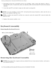
Removing and Replacing Parts : Dell Latitude C600/C500 Series Service Manual 2. NOTE: If you are installing a wireless NIC, fold and tuck the unused interface cables into the metal securing tabs. Keyboard Assembly Removing the Keyboard Screws ... slot so they do not interfere with the cover. Replace the memory module cover. NOTE: A modem-only mini-PCI card has one connector; file:///F|/Service%20Manuals/Dell/Latitude/c500-600/remove.htm (8 of mini-PCI card you are installing, either connect the interface cables to the mini-PCI card, or connect the mini...
Removing and Replacing Parts : Dell Latitude C600/C500 Series Service Manual 2. NOTE: If you are installing a wireless NIC, fold and tuck the unused interface cables into the metal securing tabs. Keyboard Assembly Removing the Keyboard Screws ... slot so they do not interfere with the cover. Replace the memory module cover. NOTE: A modem-only mini-PCI card has one connector; file:///F|/Service%20Manuals/Dell/Latitude/c500-600/remove.htm (8 of mini-PCI card you are installing, either connect the interface cables to the mini-PCI card, or connect the mini...

Service Manual
Page 16
... and handling the keyboard. 4. NOTE: Removing the center control cover provides more room to replace. Keyboard 5. Remove the hard drive. 2. Removing and Replacing Parts : Dell Latitude C600/C500 Series Service Manual NOTICE: To avoid ESD, ground yourself by using a wrist grounding strap or by touching an unpainted metal surface on the keyboard. Rest the key...
... and handling the keyboard. 4. NOTE: Removing the center control cover provides more room to replace. Keyboard 5. Remove the hard drive. 2. Removing and Replacing Parts : Dell Latitude C600/C500 Series Service Manual NOTICE: To avoid ESD, ground yourself by using a wrist grounding strap or by touching an unpainted metal surface on the keyboard. Rest the key...

Service Manual
Page 17
... by pulling up on the system board assembly. 3. Connect the keyboard flex cable to the connector pins, press the keyboard connector evenly into place. file:///F|/Service%20Manuals/Dell/Latitude/c500-600/remove.htm (10 of the computer. Removing and Replacing Parts : Dell Latitude C600/C500 Series Service Manual Keyboard Connector 8. Replacing the Keyboard Assembly 1.
... by pulling up on the system board assembly. 3. Connect the keyboard flex cable to the connector pins, press the keyboard connector evenly into place. file:///F|/Service%20Manuals/Dell/Latitude/c500-600/remove.htm (10 of the computer. Removing and Replacing Parts : Dell Latitude C600/C500 Series Service Manual Keyboard Connector 8. Replacing the Keyboard Assembly 1.

Service Manual
Page 18
... yourself by using a wrist grounding strap or by touching an unpainted metal surface on the computer. Removing and Replacing Parts : Dell Latitude C600/C500 Series Service Manual 4. Removing the Display Assembly NOTICE: You must remove the display assembly before performing the following procedure. NOTE: Always remove and ...The keys should be flush with the left and right surfaces of 40) [2/28/2004 7:53:33 AM] Display Assembly file:///F|/Service%20Manuals/Dell/Latitude/c500-600/remove.htm (11 of the palmrest. 5. the display assembly hinges pass through the back of the palmrest assembly. ...
... yourself by using a wrist grounding strap or by touching an unpainted metal surface on the computer. Removing and Replacing Parts : Dell Latitude C600/C500 Series Service Manual 4. Removing the Display Assembly NOTICE: You must remove the display assembly before performing the following procedure. NOTE: Always remove and ...The keys should be flush with the left and right surfaces of 40) [2/28/2004 7:53:33 AM] Display Assembly file:///F|/Service%20Manuals/Dell/Latitude/c500-600/remove.htm (11 of the palmrest. 5. the display assembly hinges pass through the back of the palmrest assembly. ...

Service Manual
Page 19
Removing and Replacing Parts : Dell Latitude C600/C500 Series Service Manual 1. a. b. Close the display. 4. Remove the flex cable EMI shield retention bracket that secure the EMI shield bracket to lift the right edge of the center ... center control cover up and away from the bottom case assembly. Remove the two M2 x 3-mm screws that covers the display-feed flex cable file:///F|/Service%20Manuals/Dell/Latitude/c500-600/remove.htm (12 of the computer, remove the five M2.5 x 5-mm screws labeled with the "circle D." From the back of 40) [2/28...
Removing and Replacing Parts : Dell Latitude C600/C500 Series Service Manual 1. a. b. Close the display. 4. Remove the flex cable EMI shield retention bracket that secure the EMI shield bracket to lift the right edge of the center ... center control cover up and away from the bottom case assembly. Remove the two M2 x 3-mm screws that covers the display-feed flex cable file:///F|/Service%20Manuals/Dell/Latitude/c500-600/remove.htm (12 of the computer, remove the five M2.5 x 5-mm screws labeled with the "circle D." From the back of 40) [2/28...

Service Manual
Page 20
...-600/remove.htm (13 of the connector may damage resistors and compromise EMI protection in the system. Removing and Replacing Parts : Dell Latitude C600/C500 Series Service Manual connector on the top left and right ends of the connector (see "Display Assembly"). 9. Pull straight up on the display-feed flex cable connector to ...
...-600/remove.htm (13 of the connector may damage resistors and compromise EMI protection in the system. Removing and Replacing Parts : Dell Latitude C600/C500 Series Service Manual connector on the top left and right ends of the connector (see "Display Assembly"). 9. Pull straight up on the display-feed flex cable connector to ...
Service Manual
Page 21
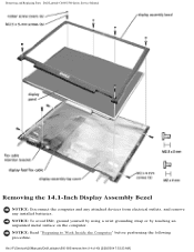
Removing and Replacing Parts : Dell Latitude C600/C500 Series Service Manual Removing the 14.1-Inch Display Assembly Bezel NOTICE: Disconnect the computer and any attached devices from electrical outlets, and remove any installed batteries. NOTICE: Read "Preparing to Work Inside the Computer" before performing the following procedure. file:///F|/Service%20Manuals/Dell/Latitude/c500-600/remove.htm (14 of 40) [2/28/2004 7:53:33 AM] NOTICE: To avoid ESD, ground yourself by using a wrist grounding strap or by touching an unpainted metal surface on the computer.
Removing and Replacing Parts : Dell Latitude C600/C500 Series Service Manual Removing the 14.1-Inch Display Assembly Bezel NOTICE: Disconnect the computer and any attached devices from electrical outlets, and remove any installed batteries. NOTICE: Read "Preparing to Work Inside the Computer" before performing the following procedure. file:///F|/Service%20Manuals/Dell/Latitude/c500-600/remove.htm (14 of 40) [2/28/2004 7:53:33 AM] NOTICE: To avoid ESD, ground yourself by using a wrist grounding strap or by touching an unpainted metal surface on the computer.


