
System Information Guide
Page 11
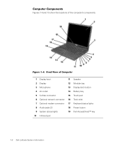
Front View of the computer's components. Figure 1-4. (Rev. 11/3/98) FILE LOCATION: D:\Eri_DProject\Dell\Temp\413CU0s\413CUeb0.fm Computer Components Figures 1-4 and 1-5 show the locations of Computer 1 Display latch 11 Speaker 2 Display 12 Modular bay 3 ...Display latch button 4 Air outlet 14 Battery bay 5 S-Video connector 15 Touch pad 6 Optional network connector 16 Track stick 7 Optional modem connector 17 Keyboard status lights 8 Audio jacks (2) 18 Power button 9 System status lights 19 Dell AccessDirect™ key 10 Infrared port 1-8 Dell Latitude System Information
Front View of the computer's components. Figure 1-4. (Rev. 11/3/98) FILE LOCATION: D:\Eri_DProject\Dell\Temp\413CU0s\413CUeb0.fm Computer Components Figures 1-4 and 1-5 show the locations of Computer 1 Display latch 11 Speaker 2 Display 12 Modular bay 3 ...Display latch button 4 Air outlet 14 Battery bay 5 S-Video connector 15 Touch pad 6 Optional network connector 16 Track stick 7 Optional modem connector 17 Keyboard status lights 8 Audio jacks (2) 18 Power button 9 System status lights 19 Dell AccessDirect™ key 10 Infrared port 1-8 Dell Latitude System Information
System Information Guide
Page 14
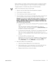
...off, continue. • For Windows 2000, use suspend-to replace the battery with the other hand. Depending on a French keyboard). support.dell.com Dell Latitude System Information 1-11 NOTE: For full instructions, see Figure 1-6). If the only battery in the computer is enabled in hibernate... shuts down and you remove the battery. c. Remove the battery from the battery bay: a. (Rev. 11/3/98) FILE LOCATION: D:\Eri_DProject\Dell\Temp\413CU0s\413CUeb0.fm Before installing a new battery, check the battery's charge, by clicking the Start button, clicking Shut Down, and clicking ...
...off, continue. • For Windows 2000, use suspend-to replace the battery with the other hand. Depending on a French keyboard). support.dell.com Dell Latitude System Information 1-11 NOTE: For full instructions, see Figure 1-6). If the only battery in the computer is enabled in hibernate... shuts down and you remove the battery. c. Remove the battery from the battery bay: a. (Rev. 11/3/98) FILE LOCATION: D:\Eri_DProject\Dell\Temp\413CU0s\413CUeb0.fm Before installing a new battery, check the battery's charge, by clicking the Start button, clicking Shut Down, and clicking ...

Service Manual
Page 1
Dell Latitude C600/C500 Series Service Manual Dell™ Latitude™ C600/C500 Series Service Manual Before You Begin Preparing to Work Inside the Computer Recommended Tools Screw Identification Removing and Replacing Parts Components Hard Drive Memory Module Mini-PCI Card Assembly Keyboard Assembly Removing the Display Assembly Display Assembly Latch ...or loss of data and tells you make better use of 2) [2/28/2004 7:53:17 AM] file:///F|/Service%20Manuals/Dell/Latitude/c500-600/index.htm (1 of your computer. NOTICE: A NOTICE indicates either potential damage to avoid the problem.
Dell Latitude C600/C500 Series Service Manual Dell™ Latitude™ C600/C500 Series Service Manual Before You Begin Preparing to Work Inside the Computer Recommended Tools Screw Identification Removing and Replacing Parts Components Hard Drive Memory Module Mini-PCI Card Assembly Keyboard Assembly Removing the Display Assembly Display Assembly Latch ...or loss of data and tells you make better use of 2) [2/28/2004 7:53:17 AM] file:///F|/Service%20Manuals/Dell/Latitude/c500-600/index.htm (1 of your computer. NOTICE: A NOTICE indicates either potential damage to avoid the problem.

Service Manual
Page 5
Before You Begin : Dell Latitude C600/C500 Series Service Manual NOTICE: When reinstalling a screw, you must use a screw of 6) [2/28/2004 7:53:27 AM] Screw Placement Hard Drive Door Security: (1 each) Keyboard to Bottom Case Assembly: (5 each) Display Assembly Bezel: (6 each) Display Assembly Hinge Bracket to Bottom Case Assembly: (5 each) Rubber Screw Covers (6 each) file:///F|/Service%20Manuals/Dell/Latitude/c500-600/begin.htm (4 of the correct diameter and length. Make sure that the screw is properly aligned with its corresponding hole, and avoid overtightening.
Before You Begin : Dell Latitude C600/C500 Series Service Manual NOTICE: When reinstalling a screw, you must use a screw of 6) [2/28/2004 7:53:27 AM] Screw Placement Hard Drive Door Security: (1 each) Keyboard to Bottom Case Assembly: (5 each) Display Assembly Bezel: (6 each) Display Assembly Hinge Bracket to Bottom Case Assembly: (5 each) Rubber Screw Covers (6 each) file:///F|/Service%20Manuals/Dell/Latitude/c500-600/begin.htm (4 of the correct diameter and length. Make sure that the screw is properly aligned with its corresponding hole, and avoid overtightening.
Service Manual
Page 8
... Series Service Manual Back to Contents Page Removing and Replacing Parts Dell™ Latitude™ C600/C500 Series Service Manual Components Hard Drive Memory Module Mini-PCI Card Assembly Keyboard Assembly Removing the Display Assembly Display Assembly Latch Hinge Covers Palmrest Assembly Microprocessor Thermal Cooling Assembly Hybrid Cooling Fan Microprocessor Module Reserve Battery Speaker...
... Series Service Manual Back to Contents Page Removing and Replacing Parts Dell™ Latitude™ C600/C500 Series Service Manual Components Hard Drive Memory Module Mini-PCI Card Assembly Keyboard Assembly Removing the Display Assembly Display Assembly Latch Hinge Covers Palmrest Assembly Microprocessor Thermal Cooling Assembly Hybrid Cooling Fan Microprocessor Module Reserve Battery Speaker...

Service Manual
Page 11
...K" in the middle of 40) [2/28/2004 7:53:33 AM] Memory Modules file:///F|/Service%20Manuals/Dell/Latitude/c500-600/remove.htm (4 of the memory module cover secures the keyboard assembly and does not secure the memory module cover. NOTICE: Read "Preparing to release the two ... strap or by touching an unpainted metal surface on the computer. Remove the memory module cover: a. Removing and Replacing Parts : Dell Latitude C600/C500 Series Service Manual Memory Module Cover Removing the Memory Module Cover NOTICE: Disconnect the computer and any attached devices from electrical outlets...
...K" in the middle of 40) [2/28/2004 7:53:33 AM] Memory Modules file:///F|/Service%20Manuals/Dell/Latitude/c500-600/remove.htm (4 of the memory module cover secures the keyboard assembly and does not secure the memory module cover. NOTICE: Read "Preparing to release the two ... strap or by touching an unpainted metal surface on the computer. Remove the memory module cover: a. Removing and Replacing Parts : Dell Latitude C600/C500 Series Service Manual Memory Module Cover Removing the Memory Module Cover NOTICE: Disconnect the computer and any attached devices from electrical outlets...
Service Manual
Page 15
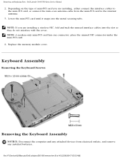
... the cover. NOTE: A modem-only mini-PCI card has one connector; Replace the memory module cover. file:///F|/Service%20Manuals/Dell/Latitude/c500-600/remove.htm (8 of mini-PCI card you are installing, either connect the interface cables to the internal antenna....Keyboard Assembly Removing the Keyboard Screws Removing the Keyboard Assembly NOTICE: Disconnect the computer and any attached devices from the mini-PCI card to the mini-PCI card, or connect the mini-coax antenna cable from electrical outlets, and remove any installed batteries. Removing and Replacing Parts : Dell Latitude C600...
... the cover. NOTE: A modem-only mini-PCI card has one connector; Replace the memory module cover. file:///F|/Service%20Manuals/Dell/Latitude/c500-600/remove.htm (8 of mini-PCI card you are installing, either connect the interface cables to the internal antenna....Keyboard Assembly Removing the Keyboard Screws Removing the Keyboard Assembly NOTICE: Disconnect the computer and any attached devices from the mini-PCI card to the mini-PCI card, or connect the mini-coax antenna cable from electrical outlets, and remove any installed batteries. Removing and Replacing Parts : Dell Latitude C600...

Service Manual
Page 16
... five M2.5 x 12-mm screws from the palmrest assembly, use a small, flat- Be careful when removing and handling the keyboard. 4. NOTICE: The key caps on the computer. Removing and Replacing Parts : Dell Latitude C600/C500 Series Service Manual NOTICE: To avoid ESD, ground yourself by using a wrist grounding strap or by touching an unpainted...
... five M2.5 x 12-mm screws from the palmrest assembly, use a small, flat- Be careful when removing and handling the keyboard. 4. NOTICE: The key caps on the computer. Removing and Replacing Parts : Dell Latitude C600/C500 Series Service Manual NOTICE: To avoid ESD, ground yourself by using a wrist grounding strap or by touching an unpainted...

Service Manual
Page 17
Removing and Replacing Parts : Dell Latitude C600/C500 Series Service Manual Keyboard Connector 8. Remove the keyboard assembly from the interface connector on the system board assembly by pulling up on the palmrest at the front of the ... assembly. 3. Carefully turn the keyboard over and fit the keyboard into the interface connector, and do not reverse the keyboard connector. 2. file:///F|/Service%20Manuals/Dell/Latitude/c500-600/remove.htm (10 of the computer. Disconnect the keyboard flex cable from the bottom case assembly. Connect the keyboard flex cable to the connector pins...
Removing and Replacing Parts : Dell Latitude C600/C500 Series Service Manual Keyboard Connector 8. Remove the keyboard assembly from the interface connector on the system board assembly by pulling up on the palmrest at the front of the ... assembly. 3. Carefully turn the keyboard over and fit the keyboard into the interface connector, and do not reverse the keyboard connector. 2. file:///F|/Service%20Manuals/Dell/Latitude/c500-600/remove.htm (10 of the computer. Disconnect the keyboard flex cable from the bottom case assembly. Connect the keyboard flex cable to the connector pins...

Service Manual
Page 18
... the Display Assembly NOTICE: You must remove the display assembly before performing the following procedure. Removing and Replacing Parts : Dell Latitude C600/C500 Series Service Manual 4. NOTICE: To avoid ESD, ground yourself by using a wrist grounding strap or by touching an... NOTE: Always remove and replace the display panel as a complete assembly. Display Assembly file:///F|/Service%20Manuals/Dell/Latitude/c500-600/remove.htm (11 of the palmrest. 5. Check that the keyboard is correctly installed. The keys should be flush with the left and right surfaces of 40) [2/28...
... the Display Assembly NOTICE: You must remove the display assembly before performing the following procedure. Removing and Replacing Parts : Dell Latitude C600/C500 Series Service Manual 4. NOTICE: To avoid ESD, ground yourself by using a wrist grounding strap or by touching an... NOTE: Always remove and replace the display panel as a complete assembly. Display Assembly file:///F|/Service%20Manuals/Dell/Latitude/c500-600/remove.htm (11 of the palmrest. 5. Check that the keyboard is correctly installed. The keys should be flush with the left and right surfaces of 40) [2/28...

Service Manual
Page 32
...before you remove the palmrest assembly; file:///F|/Service%20Manuals/Dell/Latitude/c500-600/remove.htm (25 of the palmrest assembly. Removing and Replacing Parts : Dell Latitude C600/C500 Series Service Manual Removing the Palmrest Assembly Screws ...Removing the Palmrest Assembly NOTICE: Disconnect the computer and any attached devices from electrical outlets, and remove any installed batteries. NOTICE: You must remove the display assembly before performing the following procedure. 1. Remove the keyboard...
...before you remove the palmrest assembly; file:///F|/Service%20Manuals/Dell/Latitude/c500-600/remove.htm (25 of the palmrest assembly. Removing and Replacing Parts : Dell Latitude C600/C500 Series Service Manual Removing the Palmrest Assembly Screws ...Removing the Palmrest Assembly NOTICE: Disconnect the computer and any attached devices from electrical outlets, and remove any installed batteries. NOTICE: You must remove the display assembly before performing the following procedure. 1. Remove the keyboard...

Service Manual
Page 33
...and remove the three M2 x 3-mm screws that secure the palmrest to the bottom case assembly. q Remove the M2 x 3-mm screw located underneath the keyboard, on the system board assembly. Palmrest Assembly 8. Using the plastic scribe along the edge of 40) [2/28/2004 7:53:33 AM] Remove the two ... from the touch pad connector on the right side of the bottom case assembly, underneath the display assembly. Removing and Replacing Parts : Dell Latitude C600/C500 Series Service Manual 3. Turn the computer over and remove the three M2.5 x 12-mm screws that are labeled with a "circle P." 6.
...and remove the three M2 x 3-mm screws that secure the palmrest to the bottom case assembly. q Remove the M2 x 3-mm screw located underneath the keyboard, on the system board assembly. Palmrest Assembly 8. Using the plastic scribe along the edge of 40) [2/28/2004 7:53:33 AM] Remove the two ... from the touch pad connector on the right side of the bottom case assembly, underneath the display assembly. Removing and Replacing Parts : Dell Latitude C600/C500 Series Service Manual 3. Turn the computer over and remove the three M2.5 x 12-mm screws that are labeled with a "circle P." 6.

Service Manual
Page 34
NOTICE: Read "Preparing to Work Inside the Computer" before performing the following procedure. 1. Remove the hard drive. 2. Remove the keyboard screws. Removing and Replacing Parts : Dell Latitude C600/C500 Series Service Manual Microprocessor Thermal Cooling Assembly Microprocessor Thermal Cooling Assembly Removing the Microprocessor Thermal Cooling Assembly NOTICE: Disconnect the computer and any attached ...
NOTICE: Read "Preparing to Work Inside the Computer" before performing the following procedure. 1. Remove the hard drive. 2. Remove the keyboard screws. Removing and Replacing Parts : Dell Latitude C600/C500 Series Service Manual Microprocessor Thermal Cooling Assembly Microprocessor Thermal Cooling Assembly Removing the Microprocessor Thermal Cooling Assembly NOTICE: Disconnect the computer and any attached ...

Service Manual
Page 35
...in consecutive order, from the system board assembly. Turn the computer over, lift the keyboard up, rotate it face down on the palmrest. 4. Removing and Replacing Parts : Dell Latitude C600/C500 Series Service Manual 3. Remove the hard drive. Remove the microprocessor thermal cooling assembly ...from 1 to 4. file:///F|/Service%20Manuals/Dell/Latitude/c500-600/remove.htm (28 of the computer, and place it...
...in consecutive order, from the system board assembly. Turn the computer over, lift the keyboard up, rotate it face down on the palmrest. 4. Removing and Replacing Parts : Dell Latitude C600/C500 Series Service Manual 3. Remove the hard drive. Remove the microprocessor thermal cooling assembly ...from 1 to 4. file:///F|/Service%20Manuals/Dell/Latitude/c500-600/remove.htm (28 of the computer, and place it...

Service Manual
Page 36
...Modules NOTICE: Hold the microprocessor down while turning the cam screw to the system board. 7. NOTICE: Do not block the keyboard screw hole when reinserting the fan cable. file:///F|/Service%20Manuals/Dell/Latitude/c500-600/remove.htm (29 of 40) [2/28/2004 7:53:33 AM] Remove the palmrest assembly. 5. Remove the... remove the hybrid cooling fan. Disconnect the fan power cable from under the EMI shield to provide access to the connector. Remove the keyboard assembly. 3. Removing and Replacing Parts : Dell Latitude C600/C500 Series Service Manual 2. Remove the display assembly. 4.
...Modules NOTICE: Hold the microprocessor down while turning the cam screw to the system board. 7. NOTICE: Do not block the keyboard screw hole when reinserting the fan cable. file:///F|/Service%20Manuals/Dell/Latitude/c500-600/remove.htm (29 of 40) [2/28/2004 7:53:33 AM] Remove the palmrest assembly. 5. Remove the... remove the hybrid cooling fan. Disconnect the fan power cable from under the EMI shield to provide access to the connector. Remove the keyboard assembly. 3. Removing and Replacing Parts : Dell Latitude C600/C500 Series Service Manual 2. Remove the display assembly. 4.

Service Manual
Page 37
...the heat transfer capability of the thermal pads. 3. Take note of 40) [2/28/2004 7:53:33 AM] file:///F|/Service%20Manuals/Dell/Latitude/c500-600/remove.htm (30 of the arrow on the microprocessor module. 4. NOTICE: To ensure maximum cooling for the microprocessor,... so that it is perpendicular to Work Inside the Computer" before performing the following procedure. 1. Removing and Replacing Parts : Dell Latitude C600/C500 Series Service Manual Removing the Microprocessor Module NOTICE: Disconnect the computer and any attached devices from electrical outlets, and remove ...
...the heat transfer capability of the thermal pads. 3. Take note of 40) [2/28/2004 7:53:33 AM] file:///F|/Service%20Manuals/Dell/Latitude/c500-600/remove.htm (30 of the arrow on the microprocessor module. 4. NOTICE: To ensure maximum cooling for the microprocessor,... so that it is perpendicular to Work Inside the Computer" before performing the following procedure. 1. Removing and Replacing Parts : Dell Latitude C600/C500 Series Service Manual Removing the Microprocessor Module NOTICE: Disconnect the computer and any attached devices from electrical outlets, and remove ...

Service Manual
Page 41
Remove the keyboard assembly. 3. Remove the display assembly. 4. Remove the hard drive. 2. file:///F|/Service%20Manuals/Dell/Latitude/c500-600/remove.htm (34 of 40) [2/28/2004 7:53:33 AM] Remove the palmrest assembly. Removing and Replacing Parts : Dell Latitude C600/C500 Series Service Manual 1.
Remove the keyboard assembly. 3. Remove the display assembly. 4. Remove the hard drive. 2. file:///F|/Service%20Manuals/Dell/Latitude/c500-600/remove.htm (34 of 40) [2/28/2004 7:53:33 AM] Remove the palmrest assembly. Removing and Replacing Parts : Dell Latitude C600/C500 Series Service Manual 1.

Service Manual
Page 43
... remove the six M2.5 x 5-mm screws labeled with a "circle B" that secure the system board assembly to the file:///F|/Service%20Manuals/Dell/Latitude/c500-600/remove.htm (36 of 40) [2/28/2004 7:53:33 AM] Verify that the PC Card ejectors do not extend from... a "circle B" that secure the fan guard to the bottom case assembly. 10. Remove the hard drive. 2. Removing and Replacing Parts : Dell Latitude C600/C500 Series Service Manual Removing the System Board NOTICE: Disconnect the computer and any installed batteries. Remove the display assembly. 4. Remove the microprocessor. ...
... remove the six M2.5 x 5-mm screws labeled with a "circle B" that secure the system board assembly to the file:///F|/Service%20Manuals/Dell/Latitude/c500-600/remove.htm (36 of 40) [2/28/2004 7:53:33 AM] Verify that the PC Card ejectors do not extend from... a "circle B" that secure the fan guard to the bottom case assembly. 10. Remove the hard drive. 2. Removing and Replacing Parts : Dell Latitude C600/C500 Series Service Manual Removing the System Board NOTICE: Disconnect the computer and any installed batteries. Remove the display assembly. 4. Remove the microprocessor. ...

Service Manual
Page 45
Replace the palmrest assembly, the display assembly, the keyboard assembly, and the hard drive. 6. Battery and Modular Bay Latch Assemblies Battery and Modular Bay Latch Assemblies file:///F|/Service%20Manuals/Dell/Latitude/c500-600/remove.htm (38 of the bottom case assembly. NOTE: After replacing...Replace the modular bay devices and any PC Cards or plastic blanks in the PC Card slot. 7. Removing and Replacing Parts : Dell Latitude C600/C500 Series Service Manual b. Replace the memory modules, mini-PCI card, speaker assemblies, and the thermal cooling assembly removed from the...
Replace the palmrest assembly, the display assembly, the keyboard assembly, and the hard drive. 6. Battery and Modular Bay Latch Assemblies Battery and Modular Bay Latch Assemblies file:///F|/Service%20Manuals/Dell/Latitude/c500-600/remove.htm (38 of the bottom case assembly. NOTE: After replacing...Replace the modular bay devices and any PC Cards or plastic blanks in the PC Card slot. 7. Removing and Replacing Parts : Dell Latitude C600/C500 Series Service Manual b. Replace the memory modules, mini-PCI card, speaker assemblies, and the thermal cooling assembly removed from the...

Service Manual
Page 46
...hard drive. 2. Remove the display assembly. 4. Remove the palmrest assembly. 5. Remove the system board. 6. Remove the keyboard assembly. 3. file:///F|/Service%20Manuals/Dell/Latitude/c500-600/remove.htm (39 of 40) [2/28/2004 7:53:33 AM] NOTICE: Read "Preparing to Work Inside ...the Computer" before performing the following procedure. 1. Removing and Replacing Parts : Dell Latitude C600/C500 Series Service Manual Removing the Battery and Modular Bay Latch Assemblies NOTICE: Disconnect the computer and any installed batteries. NOTICE: ...
...hard drive. 2. Remove the display assembly. 4. Remove the palmrest assembly. 5. Remove the system board. 6. Remove the keyboard assembly. 3. file:///F|/Service%20Manuals/Dell/Latitude/c500-600/remove.htm (39 of 40) [2/28/2004 7:53:33 AM] NOTICE: Read "Preparing to Work Inside ...the Computer" before performing the following procedure. 1. Removing and Replacing Parts : Dell Latitude C600/C500 Series Service Manual Removing the Battery and Modular Bay Latch Assemblies NOTICE: Disconnect the computer and any installed batteries. NOTICE: ...


