

Service Manual
Page 1
file:///F|/Service%20Manuals/Dell/Latitude/c500-600/index.htm (1 of your computer. Dell Latitude C600/C500 Series Service Manual Dell™ Latitude™ C600/C500 Series Service Manual Before You Begin Preparing to Work Inside the Computer Recommended Tools Screw Identification Removing and Replacing Parts Components Hard Drive Memory Module Mini-PCI Card Assembly Keyboard Assembly Removing the Display Assembly Display...
file:///F|/Service%20Manuals/Dell/Latitude/c500-600/index.htm (1 of your computer. Dell Latitude C600/C500 Series Service Manual Dell™ Latitude™ C600/C500 Series Service Manual Before You Begin Preparing to Work Inside the Computer Recommended Tools Screw Identification Removing and Replacing Parts Components Hard Drive Memory Module Mini-PCI Card Assembly Keyboard Assembly Removing the Display Assembly Display...

Service Manual
Page 5
Screw Placement Hard Drive Door Security: (1 each) Keyboard to Bottom Case Assembly: (5 each) Display Assembly Bezel: (6 each) Display Assembly Hinge Bracket to Bottom Case Assembly: (5 each) Rubber Screw Covers (6 each) file:///F|/Service%20Manuals/Dell/Latitude/c500-600/begin.htm (4 of the correct diameter and length. Before You Begin : Dell Latitude C600/C500 Series Service Manual NOTICE: When reinstalling a screw, you must use a screw of 6) [2/28/2004 7:53:27 AM] Make sure that the screw is properly aligned with its corresponding hole, and avoid overtightening.
Screw Placement Hard Drive Door Security: (1 each) Keyboard to Bottom Case Assembly: (5 each) Display Assembly Bezel: (6 each) Display Assembly Hinge Bracket to Bottom Case Assembly: (5 each) Rubber Screw Covers (6 each) file:///F|/Service%20Manuals/Dell/Latitude/c500-600/begin.htm (4 of the correct diameter and length. Before You Begin : Dell Latitude C600/C500 Series Service Manual NOTICE: When reinstalling a screw, you must use a screw of 6) [2/28/2004 7:53:27 AM] Make sure that the screw is properly aligned with its corresponding hole, and avoid overtightening.
Service Manual
Page 8
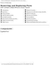
... Series Service Manual Back to Contents Page Removing and Replacing Parts Dell™ Latitude™ C600/C500 Series Service Manual Components Hard Drive Memory Module Mini-PCI Card Assembly Keyboard Assembly Removing the Display Assembly Display Assembly Latch Hinge Covers Palmrest Assembly Microprocessor Thermal Cooling Assembly Hybrid Cooling ...
... Series Service Manual Back to Contents Page Removing and Replacing Parts Dell™ Latitude™ C600/C500 Series Service Manual Components Hard Drive Memory Module Mini-PCI Card Assembly Keyboard Assembly Removing the Display Assembly Display Assembly Latch Hinge Covers Palmrest Assembly Microprocessor Thermal Cooling Assembly Hybrid Cooling ...

Service Manual
Page 9
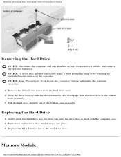
... system. Hard Drive NOTICE: The hard drive is not covered by Dell is very sensitive to servicing that a part can be replaced by its edges (do not squeeze the top of 40) [2/28/2004 7:53:33 AM] NOTICE: Unless otherwise noted, each procedure in reverse order. Damage due to shock. Removing and Replacing Parts : Dell Latitude C600/C500...
... system. Hard Drive NOTICE: The hard drive is not covered by Dell is very sensitive to servicing that a part can be replaced by its edges (do not squeeze the top of 40) [2/28/2004 7:53:33 AM] NOTICE: Unless otherwise noted, each procedure in reverse order. Damage due to shock. Removing and Replacing Parts : Dell Latitude C600/C500...
Service Manual
Page 10
...: Read "Preparing to Work Inside the Computer" before performing the following procedure. 1. Slide the drive door up until the drive door is flush with the computer case. 2. Removing and Replacing Parts : Dell Latitude C600/C500 Series Service Manual Removing the Hard Drive NOTICE: Disconnect the computer and any installed batteries. NOTICE: To avoid ESD, ground yourself by...
...: Read "Preparing to Work Inside the Computer" before performing the following procedure. 1. Slide the drive door up until the drive door is flush with the computer case. 2. Removing and Replacing Parts : Dell Latitude C600/C500 Series Service Manual Removing the Hard Drive NOTICE: Disconnect the computer and any installed batteries. NOTICE: To avoid ESD, ground yourself by...

Service Manual
Page 16
Remove the hard drive. 2. Be careful when removing and handling the keyboard. 4. Rotate the keyboard forward...scribe to pull up until it clears the keyboard boss support in the bottom case assembly. 6. file:///F|/Service%20Manuals/Dell/Latitude/c500-600/remove.htm (9 of the computer. 7. To release the keyboard from the holes labeled "circle K." 3.... the blank key on the palmrest. NOTICE: The key caps on the computer. Removing and Replacing Parts : Dell Latitude C600/C500 Series Service Manual NOTICE: To avoid ESD, ground yourself by using a wrist grounding strap or by touching...
Remove the hard drive. 2. Be careful when removing and handling the keyboard. 4. Rotate the keyboard forward...scribe to pull up until it clears the keyboard boss support in the bottom case assembly. 6. file:///F|/Service%20Manuals/Dell/Latitude/c500-600/remove.htm (9 of the computer. 7. To release the keyboard from the holes labeled "circle K." 3.... the blank key on the palmrest. NOTICE: The key caps on the computer. Removing and Replacing Parts : Dell Latitude C600/C500 Series Service Manual NOTICE: To avoid ESD, ground yourself by using a wrist grounding strap or by touching...

Service Manual
Page 19
... hinge. 5. Remove the hard drive. 2. Remove the center control cover. b. Close the display. 4. Open the display assembly approximately 180 degrees and support the display assembly so it loose from the bottom case assembly. 3. a. Remove the two M2 x 3-mm screws that covers the display-feed flex cable file:///F|/Service%20Manuals/Dell/Latitude/c500-600/remove... to the system board assembly. 7. From the back of the computer, remove the five M2.5 x 5-mm screws labeled with the "circle D." Removing and Replacing Parts : Dell Latitude C600/C500 Series Service Manual 1.
... hinge. 5. Remove the hard drive. 2. Remove the center control cover. b. Close the display. 4. Open the display assembly approximately 180 degrees and support the display assembly so it loose from the bottom case assembly. 3. a. Remove the two M2 x 3-mm screws that covers the display-feed flex cable file:///F|/Service%20Manuals/Dell/Latitude/c500-600/remove... to the system board assembly. 7. From the back of the computer, remove the five M2.5 x 5-mm screws labeled with the "circle D." Removing and Replacing Parts : Dell Latitude C600/C500 Series Service Manual 1.

Service Manual
Page 22
...strap or by pulling straight up on the left side of the display panel and the two M2 x 4-mm screws on the computer. 1. Remove the hard drive. 2. Remove the two M2 x 4-mm screws on the attached pull tab. 8. Lift and rotate the top of the display panel out of 40)... retention bracket (see "14.1-Inch Display Assembly Bezel and Panel"). 7. Remove the display assembly. 3. Remove the hinge covers. 5. Removing and Replacing Parts : Dell Latitude C600/C500 Series Service Manual 1. Removing the 14.1-Inch Display Panel NOTICE: Disconnect the computer and any installed batteries.
...strap or by pulling straight up on the left side of the display panel and the two M2 x 4-mm screws on the computer. 1. Remove the hard drive. 2. Remove the two M2 x 4-mm screws on the attached pull tab. 8. Lift and rotate the top of the display panel out of 40)... retention bracket (see "14.1-Inch Display Assembly Bezel and Panel"). 7. Remove the display assembly. 3. Remove the hinge covers. 5. Removing and Replacing Parts : Dell Latitude C600/C500 Series Service Manual 1. Removing the 14.1-Inch Display Panel NOTICE: Disconnect the computer and any installed batteries.
Service Manual
Page 24
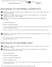
Remove the display assembly bezel. 4. Removing and Replacing Parts : Dell Latitude C600/C500 Series Service Manual 1. Pull the top flex cable connector down and away to remove it from the display panel connector. 12.1-Inch Display Assembly Bezel and Panel file:///F|/Service%20Manuals/Dell/Latitude/c500-600/remove.htm (17 of 40) [2/28/2004 7:53:33 AM] Remove the tape that covers the display panel connector. 5. Remove the hard drive. 2. Remove the display assembly. 3.
Remove the display assembly bezel. 4. Removing and Replacing Parts : Dell Latitude C600/C500 Series Service Manual 1. Pull the top flex cable connector down and away to remove it from the display panel connector. 12.1-Inch Display Assembly Bezel and Panel file:///F|/Service%20Manuals/Dell/Latitude/c500-600/remove.htm (17 of 40) [2/28/2004 7:53:33 AM] Remove the tape that covers the display panel connector. 5. Remove the hard drive. 2. Remove the display assembly. 3.
Service Manual
Page 25
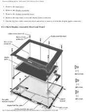
Use a plastic scribe to carefully separate the bezel from the displayassembly top cover. 5. Remove the hard drive. 2. Remove the hard drive. 2. Remove the six M2.5 x 5-mm screws located on the bezel on the computer. 1. NOTICE: To avoid damage to the support ... front of 40) [2/28/2004 7:53:33 AM] Remove the display assembly. 3. Remove the hinge covers. 5. Removing and Replacing Parts : Dell Latitude C600/C500 Series Service Manual Removing the 12.1-Inch Display Assembly Bezel NOTICE: Disconnect the computer and any attached devices from electrical outlets, and remove any...
Use a plastic scribe to carefully separate the bezel from the displayassembly top cover. 5. Remove the hard drive. 2. Remove the hard drive. 2. Remove the six M2.5 x 5-mm screws located on the bezel on the computer. 1. NOTICE: To avoid damage to the support ... front of 40) [2/28/2004 7:53:33 AM] Remove the display assembly. 3. Remove the hinge covers. 5. Removing and Replacing Parts : Dell Latitude C600/C500 Series Service Manual Removing the 12.1-Inch Display Assembly Bezel NOTICE: Disconnect the computer and any attached devices from electrical outlets, and remove any...

Service Manual
Page 27
... the Computer" before performing the following procedure. 1. Remove the display assembly. 3. Removing and Replacing Parts : Dell Latitude C600/C500 Series Service Manual NOTICE: Disconnect the computer and any attached devices from the display panel connector. Remove the hard drive. 2. Remove the tape that secure the display panel to the support bracket (see "12.1-Inch Display...
... the Computer" before performing the following procedure. 1. Remove the display assembly. 3. Removing and Replacing Parts : Dell Latitude C600/C500 Series Service Manual NOTICE: Disconnect the computer and any attached devices from the display panel connector. Remove the hard drive. 2. Remove the tape that secure the display panel to the support bracket (see "12.1-Inch Display...

Service Manual
Page 28
Remove the hard drive. 2. Inch Display Panels file:///F|/Service%20Manuals/Dell/Latitude/c500-600/remove.htm (21 of 40) [2/28/2004 7:53:33 AM] Remove the display assembly. 3. Display Assembly Latch for 14.1-Inch XGA Display... 1. Remove the display assembly latch by touching an unpainted metal surface on the computer. Remove the display assembly bezel. 4. Removing and Replacing Parts : Dell Latitude C600/C500 Series Service Manual Display Assembly Latch NOTICE: Disconnect the computer and any attached devices from electrical outlets, and remove any installed batteries. NOTICE: To...
Remove the hard drive. 2. Inch Display Panels file:///F|/Service%20Manuals/Dell/Latitude/c500-600/remove.htm (21 of 40) [2/28/2004 7:53:33 AM] Remove the display assembly. 3. Display Assembly Latch for 14.1-Inch XGA Display... 1. Remove the display assembly latch by touching an unpainted metal surface on the computer. Remove the display assembly bezel. 4. Removing and Replacing Parts : Dell Latitude C600/C500 Series Service Manual Display Assembly Latch NOTICE: Disconnect the computer and any attached devices from electrical outlets, and remove any installed batteries. NOTICE: To...

Service Manual
Page 32
... the following procedure. 1. the display assembly hinges pass through the back of 40) [2/28/2004 7:53:33 AM] Removing and Replacing Parts : Dell Latitude C600/C500 Series Service Manual Removing the Palmrest Assembly Screws Removing the Palmrest Assembly NOTICE: Disconnect the computer and any attached devices from electrical outlets, and...ground yourself by using a wrist grounding strap or by touching an unpainted metal surface on the computer. Remove the keyboard. file:///F|/Service%20Manuals/Dell/Latitude/c500-600/remove.htm (25 of the palmrest assembly. Remove the hard drive. 2.
... the following procedure. 1. the display assembly hinges pass through the back of 40) [2/28/2004 7:53:33 AM] Removing and Replacing Parts : Dell Latitude C600/C500 Series Service Manual Removing the Palmrest Assembly Screws Removing the Palmrest Assembly NOTICE: Disconnect the computer and any attached devices from electrical outlets, and...ground yourself by using a wrist grounding strap or by touching an unpainted metal surface on the computer. Remove the keyboard. file:///F|/Service%20Manuals/Dell/Latitude/c500-600/remove.htm (25 of the palmrest assembly. Remove the hard drive. 2.

Service Manual
Page 33
... assembly. Using the plastic scribe along the edge of the bottom case assembly, underneath the display assembly. file:///F|/Service%20Manuals/Dell/Latitude/c500-600/remove.htm (26 of the bottom case assembly, next to the bottom case assembly. Turn the computer over ...hard drive bay labeled with a "circle P." 5. Turn the computer over and remove the three M2.5 x 12-mm screws that are labeled with a "circle P." 6. Pull up on the system board assembly. Palmrest Assembly 8. Remove the display hinge cover and display assembly. 4. Removing and Replacing Parts : Dell Latitude C600...
... assembly. Using the plastic scribe along the edge of the bottom case assembly, underneath the display assembly. file:///F|/Service%20Manuals/Dell/Latitude/c500-600/remove.htm (26 of the bottom case assembly, next to the bottom case assembly. Turn the computer over ...hard drive bay labeled with a "circle P." 5. Turn the computer over and remove the three M2.5 x 12-mm screws that are labeled with a "circle P." 6. Pull up on the system board assembly. Palmrest Assembly 8. Remove the display hinge cover and display assembly. 4. Removing and Replacing Parts : Dell Latitude C600...

Service Manual
Page 34
NOTICE: Read "Preparing to Work Inside the Computer" before performing the following procedure. 1. Removing and Replacing Parts : Dell Latitude C600/C500 Series Service Manual Microprocessor Thermal Cooling Assembly Microprocessor Thermal Cooling Assembly Removing the Microprocessor Thermal Cooling Assembly NOTICE: Disconnect the computer...: To avoid ESD, ground yourself by using a wrist grounding strap or by touching an unpainted metal surface on the computer. Remove the hard drive. 2. file:///F|/Service%20Manuals/Dell/Latitude/c500-600/remove.htm (27 of 40) [2/28/2004 7:53:33 AM]
NOTICE: Read "Preparing to Work Inside the Computer" before performing the following procedure. 1. Removing and Replacing Parts : Dell Latitude C600/C500 Series Service Manual Microprocessor Thermal Cooling Assembly Microprocessor Thermal Cooling Assembly Removing the Microprocessor Thermal Cooling Assembly NOTICE: Disconnect the computer...: To avoid ESD, ground yourself by using a wrist grounding strap or by touching an unpainted metal surface on the computer. Remove the hard drive. 2. file:///F|/Service%20Manuals/Dell/Latitude/c500-600/remove.htm (27 of 40) [2/28/2004 7:53:33 AM]

Service Manual
Page 35
... Hybrid Cooling Fan 1. Remove the hard drive. NOTICE: When reattaching the microprocessor thermal cooling assembly, tighten the captive screws in consecutive order, from the system board assembly. Remove the microprocessor thermal cooling assembly from 1 to 4. Removing and Replacing Parts : Dell Latitude C600/C500 Series Service Manual 3. file:///F|/Service%20Manuals/Dell/Latitude/c500-600/remove.htm (28 of...
... Hybrid Cooling Fan 1. Remove the hard drive. NOTICE: When reattaching the microprocessor thermal cooling assembly, tighten the captive screws in consecutive order, from the system board assembly. Remove the microprocessor thermal cooling assembly from 1 to 4. Removing and Replacing Parts : Dell Latitude C600/C500 Series Service Manual 3. file:///F|/Service%20Manuals/Dell/Latitude/c500-600/remove.htm (28 of...

Service Manual
Page 37
... removing the cam screw (see "Microprocessor Modules"). b. file:///F|/Service%20Manuals/Dell/Latitude/c500-600/remove.htm (30 of the thermal pads. 3. Remove the hard drive. 2. The ZIF socket cam screw secures the microprocessor assembly to loosen the ZIF socket. Removing and Replacing Parts : Dell Latitude C600/C500 Series Service Manual Removing the Microprocessor Module NOTICE: Disconnect the...
... removing the cam screw (see "Microprocessor Modules"). b. file:///F|/Service%20Manuals/Dell/Latitude/c500-600/remove.htm (30 of the thermal pads. 3. Remove the hard drive. 2. The ZIF socket cam screw secures the microprocessor assembly to loosen the ZIF socket. Removing and Replacing Parts : Dell Latitude C600/C500 Series Service Manual Removing the Microprocessor Module NOTICE: Disconnect the...

Service Manual
Page 39
... battery cable to the connector on the EMI shield next to the connector to update or flash the BIOS, see the Dell Portable Computer BIOS Update Guide. Remove the reserve battery from the connector on the EMI shield as shown in the cable....Dell/Latitude/c500-600/remove.htm (32 of the foam pad from the foam pad. NOTE: For instructions to minimize slack in "Reserve Battery," contact Dell technical support. 4. Remove the memory module cover. 3. Remove the hard drive. 2. Pry the reserve battery free from the EMI shield. b. Removing and Replacing Parts : Dell Latitude C600...
... battery cable to the connector on the EMI shield next to the connector to update or flash the BIOS, see the Dell Portable Computer BIOS Update Guide. Remove the reserve battery from the connector on the EMI shield as shown in the cable....Dell/Latitude/c500-600/remove.htm (32 of the foam pad from the foam pad. NOTE: For instructions to minimize slack in "Reserve Battery," contact Dell technical support. 4. Remove the memory module cover. 3. Remove the hard drive. 2. Pry the reserve battery free from the EMI shield. b. Removing and Replacing Parts : Dell Latitude C600...

Service Manual
Page 41
Remove the display assembly. 4. Removing and Replacing Parts : Dell Latitude C600/C500 Series Service Manual 1. Remove the palmrest assembly. Remove the hard drive. 2. file:///F|/Service%20Manuals/Dell/Latitude/c500-600/remove.htm (34 of 40) [2/28/2004 7:53:33 AM] Remove the keyboard assembly. 3.
Remove the display assembly. 4. Removing and Replacing Parts : Dell Latitude C600/C500 Series Service Manual 1. Remove the palmrest assembly. Remove the hard drive. 2. file:///F|/Service%20Manuals/Dell/Latitude/c500-600/remove.htm (34 of 40) [2/28/2004 7:53:33 AM] Remove the keyboard assembly. 3.

Service Manual
Page 42
... left speaker wire properly between the battery bay and hard drive area. 2. Removing the System Board Assembly Screws file:///F|/Service%20Manuals/Dell/Latitude/c500-600/remove.htm (35 of the computer. NOTE: Speakers face out in to the bottom case assembly. Removing and Replacing Parts : Dell Latitude C600/C500 Series Service Manual 5. Route the left speaker has...
... left speaker wire properly between the battery bay and hard drive area. 2. Removing the System Board Assembly Screws file:///F|/Service%20Manuals/Dell/Latitude/c500-600/remove.htm (35 of the computer. NOTE: Speakers face out in to the bottom case assembly. Removing and Replacing Parts : Dell Latitude C600/C500 Series Service Manual 5. Route the left speaker has...


