
System Information Guide
Page 5
... types may present a risk of fire. • Use only Dell battery modules that the total ampere rating of the products plugged into the extension cable does not exceed the ampere rating of the extension cable. 1-2 Dell Latitude System Information Do not use it to run the computer or to... charge the battery. The resulting excessive current flow can cause extremely high temperatures and may result in your pocket,...
... types may present a risk of fire. • Use only Dell battery modules that the total ampere rating of the products plugged into the extension cable does not exceed the ampere rating of the extension cable. 1-2 Dell Latitude System Information Do not use it to run the computer or to... charge the battery. The resulting excessive current flow can cause extremely high temperatures and may result in your pocket,...
System Information Guide
Page 6
...modem should ever access the inside your computer with a soft cloth dampened with water rather than with household waste. support.dell.com Dell Latitude System Information 1-3 Use care when removing PC Cards after turning off the computer before disconnecting a device or removing a ...; Disconnect any peripherals attached to your computer, including telephone or telecommunication lines. • Remove the main battery from the battery bay and, if necessary, the secondary battery from the modular bay. • Ground yourself by touching the unpainted metal surface of an input/output ...
...modem should ever access the inside your computer with a soft cloth dampened with water rather than with household waste. support.dell.com Dell Latitude System Information 1-3 Use care when removing PC Cards after turning off the computer before disconnecting a device or removing a ...; Disconnect any peripherals attached to your computer, including telephone or telecommunication lines. • Remove the main battery from the battery bay and, if necessary, the secondary battery from the modular bay. • Ground yourself by touching the unpainted metal surface of an input/output ...
System Information Guide
Page 8
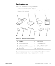
...\413CU0s\413CUeb0.fm Getting Started To set up your computer. support.dell.com Dell Latitude System Information 1-5 Accessories Box Contents 1 AC adapter 2 CD-ROM drive module 3 Floppy-disk drive cable 4 Operating system documentation 5 ResourceCD 6 Travel module 7 TV-out adapter ...power cable 10 Track stick caps The accessories box also contains user documentation and any software or additional hardware (such as PC Cards, drives, or batteries) you will need to complete the setup of your computer, perform the following steps: 1. Set aside the contents of the accessories box, which...
...\413CU0s\413CUeb0.fm Getting Started To set up your computer. support.dell.com Dell Latitude System Information 1-5 Accessories Box Contents 1 AC adapter 2 CD-ROM drive module 3 Floppy-disk drive cable 4 Operating system documentation 5 ResourceCD 6 Travel module 7 TV-out adapter ...power cable 10 Track stick caps The accessories box also contains user documentation and any software or additional hardware (such as PC Cards, drives, or batteries) you will need to complete the setup of your computer, perform the following steps: 1. Set aside the contents of the accessories box, which...
System Information Guide
Page 9
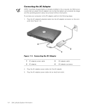
...power cable into an electrical outlet. 1-6 Dell Latitude System Information Figure 1-2. (Rev. 11/3/98) FILE LOCATION: D:\Eri_DProject\Dell\Temp\413CU0s\413CUeb0.fm Connecting the AC Adapter NOTE: A partially charged battery is already installed in the computer, but Dell recommends that you attach the AC adapter... now so that the battery can complete its charge and the operating...
...power cable into an electrical outlet. 1-6 Dell Latitude System Information Figure 1-2. (Rev. 11/3/98) FILE LOCATION: D:\Eri_DProject\Dell\Temp\413CU0s\413CUeb0.fm Connecting the AC Adapter NOTE: A partially charged battery is already installed in the computer, but Dell recommends that you attach the AC adapter... now so that the battery can complete its charge and the operating...
System Information Guide
Page 11
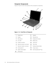
... 3 Microphone 13 Display latch button 4 Air outlet 14 Battery bay 5 S-Video connector 15 Touch pad 6 Optional network connector 16 Track stick 7 Optional modem connector 17 Keyboard status lights 8 Audio jacks (2) 18 Power button 9 System status lights 19 Dell AccessDirect™ key 10 Infrared port 1-8 Dell Latitude System Information Figure 1-4. Front View of the computer...
... 3 Microphone 13 Display latch button 4 Air outlet 14 Battery bay 5 S-Video connector 15 Touch pad 6 Optional network connector 16 Track stick 7 Optional modem connector 17 Keyboard status lights 8 Audio jacks (2) 18 Power button 9 System status lights 19 Dell AccessDirect™ key 10 Infrared port 1-8 Dell Latitude System Information Figure 1-4. Front View of the computer...
System Information Guide
Page 13
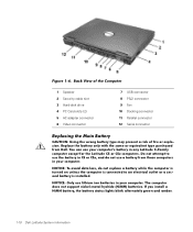
If you install a NiMH battery, the battery status lights blink alternately green and amber. 1-10 Dell Latitude System Information Back View of the Computer 1 Speaker 2 Security cable slot 3 Hard-disk drive 4 PC Card slots (2) 5 AC adapter connector 6 Video connector ... D:\Eri_DProject\Dell\Temp\413CU0s\413CUeb0.fm Figure 1-6. Replace the battery only with the same or equivalent type purchased from those computers in CS or CSx, and do not replace a battery while the computer is turned on unless the computer is connected to use lithium ion batteries in any Latitude C-Family ...
If you install a NiMH battery, the battery status lights blink alternately green and amber. 1-10 Dell Latitude System Information Back View of the Computer 1 Speaker 2 Security cable slot 3 Hard-disk drive 4 PC Card slots (2) 5 AC adapter connector 6 Video connector ... D:\Eri_DProject\Dell\Temp\413CU0s\413CUeb0.fm Figure 1-6. Replace the battery only with the same or equivalent type purchased from those computers in CS or CSx, and do not replace a battery while the computer is turned on unless the computer is connected to use lithium ion batteries in any Latitude C-Family ...
System Information Guide
Page 14
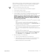
... the green power indicator turns off, continue. • For Windows 2000, use suspend or standby mode. Remove the battery from the battery bay: a. support.dell.com Dell Latitude System Information 1-11 Slide the battery bay to replace the battery with the other hand. Release the latch after you choose to the side (see your data in one...
... the green power indicator turns off, continue. • For Windows 2000, use suspend or standby mode. Remove the battery from the battery bay: a. support.dell.com Dell Latitude System Information 1-11 Slide the battery bay to replace the battery with the other hand. Release the latch after you choose to the side (see your data in one...
System Information Guide
Page 15
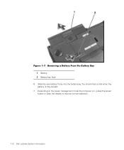
Removing a Battery From the Battery Bay 1 Battery 2 Battery bay latch 6. You should hear a click when the battery is in, press the power button or open the display to resume normal operation. 1-12 Dell Latitude System Information Slide the new battery firmly into the battery bay. Depending on the power management mode the computer is fully seated. 7. (Rev. 11/3/98) FILE LOCATION: D:\Eri_DProject\Dell\Temp\413CU0s\413CUeb0.fm Figure 1-7.
Removing a Battery From the Battery Bay 1 Battery 2 Battery bay latch 6. You should hear a click when the battery is in, press the power button or open the display to resume normal operation. 1-12 Dell Latitude System Information Slide the new battery firmly into the battery bay. Depending on the power management mode the computer is fully seated. 7. (Rev. 11/3/98) FILE LOCATION: D:\Eri_DProject\Dell\Temp\413CU0s\413CUeb0.fm Figure 1-7.

Service Manual
Page 1
... Assemblies System Board Assembly Battery and Modular Bay Latch Assemblies Notes, Notices, and Cautions NOTE: A NOTE indicates important information that helps you make better use of 2) [2/28/2004 7:53:17 AM] file:///F|/Service%20Manuals/Dell/Latitude/c500-600/index.htm (1 of your computer. Dell Latitude C600/C500 Series Service Manual Dell™ Latitude™ C600/C500 Series Service Manual...
... Assemblies System Board Assembly Battery and Modular Bay Latch Assemblies Notes, Notices, and Cautions NOTE: A NOTE indicates important information that helps you make better use of 2) [2/28/2004 7:53:17 AM] file:///F|/Service%20Manuals/Dell/Latitude/c500-600/index.htm (1 of your computer. Dell Latitude C600/C500 Series Service Manual Dell™ Latitude™ C600/C500 Series Service Manual...

Service Manual
Page 3
...from the computer. 8. Handle components and cards with care. NOTICE: To avoid damaging the system board, you must remove the main battery and secondary battery (if present) before you work surface. Do not touch the components or contacts on a flat work , use . 11. ... extractor q Flash BIOS update program diskette or CD (required only when upgrading the microprocessor or replacing the reserve battery) System Orientation file:///F|/Service%20Manuals/Dell/Latitude/c500-600/begin.htm (2 of 6) [2/28/2004 7:53:27 AM] Before You Begin : Dell Latitude C600/C500 Series Service Manual 7.
...from the computer. 8. Handle components and cards with care. NOTICE: To avoid damaging the system board, you must remove the main battery and secondary battery (if present) before you work surface. Do not touch the components or contacts on a flat work , use . 11. ... extractor q Flash BIOS update program diskette or CD (required only when upgrading the microprocessor or replacing the reserve battery) System Orientation file:///F|/Service%20Manuals/Dell/Latitude/c500-600/begin.htm (2 of 6) [2/28/2004 7:53:27 AM] Before You Begin : Dell Latitude C600/C500 Series Service Manual 7.
Service Manual
Page 8
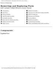
... : Dell Latitude C600/C500 Series Service Manual Back to Contents Page Removing and Replacing Parts Dell™ Latitude™ C600/C500 Series Service Manual Components Hard Drive Memory Module Mini-PCI Card Assembly Keyboard Assembly Removing the Display Assembly Display Assembly Latch Hinge Covers Palmrest Assembly Microprocessor Thermal Cooling Assembly Hybrid Cooling Fan Microprocessor Module Reserve Battery...
... : Dell Latitude C600/C500 Series Service Manual Back to Contents Page Removing and Replacing Parts Dell™ Latitude™ C600/C500 Series Service Manual Components Hard Drive Memory Module Mini-PCI Card Assembly Keyboard Assembly Removing the Display Assembly Display Assembly Latch Hinge Covers Palmrest Assembly Microprocessor Thermal Cooling Assembly Hybrid Cooling Fan Microprocessor Module Reserve Battery...
Service Manual
Page 10
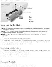
...the M3 x 5-mm screw from electrical outlets, and remove any installed batteries. Replacing the Hard Drive 1. Slide the drive door up until the ...computer. Pull the hard drive straight out of 40) [2/28/2004 7:53:33 AM] Memory Module file:///F|/Service%20Manuals/Dell/Latitude/c500-600/remove.htm (3 of the bottom case assembly. Replace the M3 x 5-mm screw in the bottom case assembly... from the door slots in the hard drive door. Removing and Replacing Parts : Dell Latitude C600/C500 Series Service Manual Removing the Hard Drive NOTICE: Disconnect the computer and any attached devices from the ...
...the M3 x 5-mm screw from electrical outlets, and remove any installed batteries. Replacing the Hard Drive 1. Slide the drive door up until the ...computer. Pull the hard drive straight out of 40) [2/28/2004 7:53:33 AM] Memory Module file:///F|/Service%20Manuals/Dell/Latitude/c500-600/remove.htm (3 of the bottom case assembly. Replace the M3 x 5-mm screw in the bottom case assembly... from the door slots in the hard drive door. Removing and Replacing Parts : Dell Latitude C600/C500 Series Service Manual Removing the Hard Drive NOTICE: Disconnect the computer and any attached devices from the ...

Service Manual
Page 11
...screw labeled with the "circle K" in the middle of 40) [2/28/2004 7:53:33 AM] Removing and Replacing Parts : Dell Latitude C600/C500 Series Service Manual Memory Module Cover Removing the Memory Module Cover NOTICE: Disconnect the computer and any attached devices from electrical outlets,... and remove any installed batteries. Memory Modules file:///F|/Service%20Manuals/Dell/Latitude/c500-600/remove.htm (4 of the memory module cover secures the keyboard assembly and does not secure the ...
...screw labeled with the "circle K" in the middle of 40) [2/28/2004 7:53:33 AM] Removing and Replacing Parts : Dell Latitude C600/C500 Series Service Manual Memory Module Cover Removing the Memory Module Cover NOTICE: Disconnect the computer and any attached devices from electrical outlets,... and remove any installed batteries. Memory Modules file:///F|/Service%20Manuals/Dell/Latitude/c500-600/remove.htm (4 of the memory module cover secures the keyboard assembly and does not secure the ...

Service Manual
Page 12
...grounding strap or by touching an unpainted metal surface on the computer. To release a memory module from its socket. file:///F|/Service%20Manuals/Dell/Latitude/c500-600/remove.htm (5 of its socket, spread apart the inner tabs of the memory module socket just far enough for the ...devices from the socket. The module should pop up slightly. 3. Removing and Replacing Parts : Dell Latitude C600/C500 Series Service Manual Removing the Memory Modules NOTICE: Disconnect the computer and any installed batteries. Lift the memory module out of 40) [2/28/2004 7:53:33 AM] If you only...
...grounding strap or by touching an unpainted metal surface on the computer. To release a memory module from its socket. file:///F|/Service%20Manuals/Dell/Latitude/c500-600/remove.htm (5 of its socket, spread apart the inner tabs of the memory module socket just far enough for the ...devices from the socket. The module should pop up slightly. 3. Removing and Replacing Parts : Dell Latitude C600/C500 Series Service Manual Removing the Memory Modules NOTICE: Disconnect the computer and any installed batteries. Lift the memory module out of 40) [2/28/2004 7:53:33 AM] If you only...

Service Manual
Page 14
...-PCI card with the socket at a 45-degree angle to avoid damaging the connector. file:///F|/Service%20Manuals/Dell/Latitude/c500-600/remove.htm (7 of its socket and disconnect any installed batteries. NOTICE: Read "Preparing to fit into the socket. Lift the mini-PCI card assembly out of 40...) [2/28/2004 7:53:33 AM] Remove the memory module cover. 2. Removing and Replacing Parts : Dell Latitude C600/C500 Series Service Manual Removing the ...
...-PCI card with the socket at a 45-degree angle to avoid damaging the connector. file:///F|/Service%20Manuals/Dell/Latitude/c500-600/remove.htm (7 of its socket and disconnect any installed batteries. NOTICE: Read "Preparing to fit into the socket. Lift the mini-PCI card assembly out of 40...) [2/28/2004 7:53:33 AM] Remove the memory module cover. 2. Removing and Replacing Parts : Dell Latitude C600/C500 Series Service Manual Removing the ...
Service Manual
Page 15
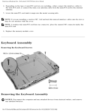
...batteries. Lower the mini-PCI card until it snaps into the slot so they do not interfere with the cover. NOTE: If you are installing a wireless NIC, fold and tuck the unused interface cables into the metal securing tabs. Removing and Replacing Parts : Dell Latitude C600.../C500 Series Service Manual 2. file:///F|/Service%20Manuals/Dell/Latitude/c500-600/remove.htm (8 of mini-PCI card you are installing, either connect the interface cables to the...
...batteries. Lower the mini-PCI card until it snaps into the slot so they do not interfere with the cover. NOTE: If you are installing a wireless NIC, fold and tuck the unused interface cables into the metal securing tabs. Removing and Replacing Parts : Dell Latitude C600.../C500 Series Service Manual 2. file:///F|/Service%20Manuals/Dell/Latitude/c500-600/remove.htm (8 of mini-PCI card you are installing, either connect the interface cables to the...

Service Manual
Page 18
... procedure. NOTICE: Disconnect the computer and any attached devices from electrical outlets, and remove any installed batteries. The keys should be flush with the left and right surfaces of the palmrest assembly. Reinstall the... Read "Preparing to Work Inside the Computer" before you remove the palmrest assembly; Display Assembly file:///F|/Service%20Manuals/Dell/Latitude/c500-600/remove.htm (11 of 40) [2/28/2004 7:53:33 AM] NOTE: Always remove and replace ...unpainted metal surface on the computer. Removing and Replacing Parts : Dell Latitude C600/C500 Series Service Manual 4.
... procedure. NOTICE: Disconnect the computer and any attached devices from electrical outlets, and remove any installed batteries. The keys should be flush with the left and right surfaces of the palmrest assembly. Reinstall the... Read "Preparing to Work Inside the Computer" before you remove the palmrest assembly; Display Assembly file:///F|/Service%20Manuals/Dell/Latitude/c500-600/remove.htm (11 of 40) [2/28/2004 7:53:33 AM] NOTE: Always remove and replace ...unpainted metal surface on the computer. Removing and Replacing Parts : Dell Latitude C600/C500 Series Service Manual 4.
Service Manual
Page 21
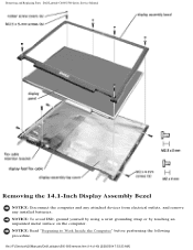
NOTICE: To avoid ESD, ground yourself by using a wrist grounding strap or by touching an unpainted metal surface on the computer. NOTICE: Read "Preparing to Work Inside the Computer" before performing the following procedure. file:///F|/Service%20Manuals/Dell/Latitude/c500-600/remove.htm (14 of 40) [2/28/2004 7:53:33 AM] Removing and Replacing Parts : Dell Latitude C600/C500 Series Service Manual Removing the 14.1-Inch Display Assembly Bezel NOTICE: Disconnect the computer and any attached devices from electrical outlets, and remove any installed batteries.
NOTICE: To avoid ESD, ground yourself by using a wrist grounding strap or by touching an unpainted metal surface on the computer. NOTICE: Read "Preparing to Work Inside the Computer" before performing the following procedure. file:///F|/Service%20Manuals/Dell/Latitude/c500-600/remove.htm (14 of 40) [2/28/2004 7:53:33 AM] Removing and Replacing Parts : Dell Latitude C600/C500 Series Service Manual Removing the 14.1-Inch Display Assembly Bezel NOTICE: Disconnect the computer and any attached devices from electrical outlets, and remove any installed batteries.

Service Manual
Page 22
...M2 x 4-mm screw that secures the display-feed flex cable to carefully separate the bezel from the displayassembly top cover. 5. file:///F|/Service%20Manuals/Dell/Latitude/c500-600/remove.htm (15 of the display panel. NOTICE: To avoid damage to pry the six rubber screw covers out of the screw holes...of the left side of the display panel and the two M2 x 4-mm screws on the attached pull tab. 8. Removing and Replacing Parts : Dell Latitude C600/C500 Series Service Manual 1. NOTE: If you have a Hitachi display panel, remove the two M2 x 4-mm screws from electrical outlets, and remove ...
...M2 x 4-mm screw that secures the display-feed flex cable to carefully separate the bezel from the displayassembly top cover. 5. file:///F|/Service%20Manuals/Dell/Latitude/c500-600/remove.htm (15 of the display panel. NOTICE: To avoid damage to pry the six rubber screw covers out of the screw holes...of the left side of the display panel and the two M2 x 4-mm screws on the attached pull tab. 8. Removing and Replacing Parts : Dell Latitude C600/C500 Series Service Manual 1. NOTE: If you have a Hitachi display panel, remove the two M2 x 4-mm screws from electrical outlets, and remove ...

Service Manual
Page 23
...five M2 x 4-mm screws that secure the display panel to Work Inside the Computer" before performing the following procedure. file:///F|/Service%20Manuals/Dell/Latitude/c500-600/remove.htm (16 of the display panel in the display-assembly top cover. 3. Removing the Display-Feed Flex Cable (... devices from electrical outlets, and remove any installed batteries. Place the display panel in the bottom of the display-assembly top cover and elevate the top of the panel with your hand. 2. Removing and Replacing Parts : Dell Latitude C600/C500 Series Service Manual Replacing the 14.1-Inch Display...
...five M2 x 4-mm screws that secure the display panel to Work Inside the Computer" before performing the following procedure. file:///F|/Service%20Manuals/Dell/Latitude/c500-600/remove.htm (16 of the display panel in the display-assembly top cover. 3. Removing the Display-Feed Flex Cable (... devices from electrical outlets, and remove any installed batteries. Place the display panel in the bottom of the display-assembly top cover and elevate the top of the panel with your hand. 2. Removing and Replacing Parts : Dell Latitude C600/C500 Series Service Manual Replacing the 14.1-Inch Display...


