

Service Manual
Page 1
file:///F|/Service%20Manuals/Dell/Latitude/c500-600/index.htm (1 of your computer. Dell Latitude C600/C500 Series Service Manual Dell™ Latitude™ C600/C500 Series Service Manual Before You Begin Preparing to Work Inside the Computer Recommended Tools Screw Identification Removing and Replacing Parts Components Hard Drive Memory Module Mini-PCI Card Assembly Keyboard Assembly Removing the Display Assembly Display...
file:///F|/Service%20Manuals/Dell/Latitude/c500-600/index.htm (1 of your computer. Dell Latitude C600/C500 Series Service Manual Dell™ Latitude™ C600/C500 Series Service Manual Before You Begin Preparing to Work Inside the Computer Recommended Tools Screw Identification Removing and Replacing Parts Components Hard Drive Memory Module Mini-PCI Card Assembly Keyboard Assembly Removing the Display Assembly Display...
Service Manual
Page 8
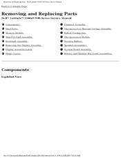
... Back to Contents Page Removing and Replacing Parts Dell™ Latitude™ C600/C500 Series Service Manual Components Hard Drive Memory Module Mini-PCI Card Assembly Keyboard Assembly Removing the... Display Assembly Display Assembly Latch Hinge Covers Palmrest Assembly Microprocessor Thermal Cooling Assembly Hybrid Cooling Fan Microprocessor Module Reserve Battery Speaker Assemblies System Board Assembly Battery and Modular Bay Latch Assemblies Components Exploded View file:///F|/Service%20Manuals/Dell/Latitude/c500-600...
... Back to Contents Page Removing and Replacing Parts Dell™ Latitude™ C600/C500 Series Service Manual Components Hard Drive Memory Module Mini-PCI Card Assembly Keyboard Assembly Removing the... Display Assembly Display Assembly Latch Hinge Covers Palmrest Assembly Microprocessor Thermal Cooling Assembly Hybrid Cooling Fan Microprocessor Module Reserve Battery Speaker Assemblies System Board Assembly Battery and Modular Bay Latch Assemblies Components Exploded View file:///F|/Service%20Manuals/Dell/Latitude/c500-600...
Service Manual
Page 10
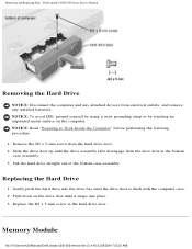
NOTICE: Read "Preparing to Work Inside the Computer" before performing the following procedure. 1. Push down on the computer. Memory Module file:///F|/Service%20Manuals/Dell/Latitude/c500-600/remove.htm (3 of the bottom case assembly. Slide the drive door up until the drive door is flush with ...the computer case. 2. Replace the M3 x 5-mm screw in the bottom case assembly. 3. Removing and Replacing Parts : Dell Latitude C600/C500 Series ...
NOTICE: Read "Preparing to Work Inside the Computer" before performing the following procedure. 1. Push down on the computer. Memory Module file:///F|/Service%20Manuals/Dell/Latitude/c500-600/remove.htm (3 of the bottom case assembly. Slide the drive door up until the drive door is flush with ...the computer case. 2. Replace the M3 x 5-mm screw in the bottom case assembly. 3. Removing and Replacing Parts : Dell Latitude C600/C500 Series ...

Service Manual
Page 11
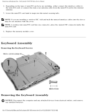
Remove the memory module cover: a. b. Memory Modules file:///F|/Service%20Manuals/Dell/Latitude/c500-600/remove.htm (4 of the memory module cover secures the keyboard assembly and does not secure the memory module cover. Removing and Replacing Parts : Dell Latitude C600/C500 Series Service Manual Memory Module Cover Removing the Memory Module Cover NOTICE: Disconnect the computer and any attached devices from electrical outlets...
Remove the memory module cover: a. b. Memory Modules file:///F|/Service%20Manuals/Dell/Latitude/c500-600/remove.htm (4 of the memory module cover secures the keyboard assembly and does not secure the memory module cover. Removing and Replacing Parts : Dell Latitude C600/C500 Series Service Manual Memory Module Cover Removing the Memory Module Cover NOTICE: Disconnect the computer and any attached devices from electrical outlets...

Service Manual
Page 12
... and Replacing Parts : Dell Latitude C600/C500 Series Service Manual Removing the Memory Modules NOTICE: Disconnect the computer and any attached devices from the socket. Remove the memory module cover. 2. The module should pop up slightly. 3. To release a memory module from its socket,... Install a second memory module in the socket labeled "JDIM1." Lift the memory module out of the memory module socket just far enough for the memory module to Work Inside the Computer" before performing the following procedure. 1. file:///F|/Service%20Manuals/Dell/Latitude/c500-600/remove.htm (5 ...
... and Replacing Parts : Dell Latitude C600/C500 Series Service Manual Removing the Memory Modules NOTICE: Disconnect the computer and any attached devices from the socket. Remove the memory module cover. 2. The module should pop up slightly. 3. To release a memory module from its socket,... Install a second memory module in the socket labeled "JDIM1." Lift the memory module out of the memory module socket just far enough for the memory module to Work Inside the Computer" before performing the following procedure. 1. file:///F|/Service%20Manuals/Dell/Latitude/c500-600/remove.htm (5 ...

Service Manual
Page 13
...memory module down and tighten the two captive screws. Rotate the memory module cover down until it . 4. A mini-PCI card assembly may consist of the memory module socket. Removing and Replacing Parts : Dell Latitude C600/C500 Series Service Manual NOTE: Memory... modules are keyed, or designed to fit into place. Insert the tabs on the memory module cover into the memory...inserted at a 45-degree angle, press the memory module's edge connector firmly into the bottom case...
...memory module down and tighten the two captive screws. Rotate the memory module cover down until it . 4. A mini-PCI card assembly may consist of the memory module socket. Removing and Replacing Parts : Dell Latitude C600/C500 Series Service Manual NOTE: Memory... modules are keyed, or designed to fit into place. Insert the tabs on the memory module cover into the memory...inserted at a 45-degree angle, press the memory module's edge connector firmly into the bottom case...

Service Manual
Page 14
... batteries. NOTICE: The mini-PCI card is keyed, or designed to Work Inside the Computer" before performing the following procedure. 1. Removing and Replacing Parts : Dell Latitude C600/C500 Series Service Manual Removing the Mini-PCI Card Assembly NOTICE: Disconnect the computer and any attached devices from its socket, spread apart the metal... up slightly. 3. Do not force the connection. 1. Lift the mini-PCI card assembly out of 40) [2/28/2004 7:53:33 AM] file:///F|/Service%20Manuals/Dell/Latitude/c500-600/remove.htm (7 of its socket and disconnect any attached cables. Remove the...
... batteries. NOTICE: The mini-PCI card is keyed, or designed to Work Inside the Computer" before performing the following procedure. 1. Removing and Replacing Parts : Dell Latitude C600/C500 Series Service Manual Removing the Mini-PCI Card Assembly NOTICE: Disconnect the computer and any attached devices from its socket, spread apart the metal... up slightly. 3. Do not force the connection. 1. Lift the mini-PCI card assembly out of 40) [2/28/2004 7:53:33 AM] file:///F|/Service%20Manuals/Dell/Latitude/c500-600/remove.htm (7 of its socket and disconnect any attached cables. Remove the...
Service Manual
Page 15
...only mini-PCI card has one connector; Depending on the type of 40) [2/28/2004 7:53:33 AM] Replace the memory module cover. file:///F|/Service%20Manuals/Dell/Latitude/c500-600/remove.htm (8 of mini-PCI card you are installing, either connect the interface cables to the mini-PCI card, or ...3. Lower the mini-PCI card until it snaps into the slot so they do not interfere with the cover. Removing and Replacing Parts : Dell Latitude C600/C500 Series Service Manual 2. NOTE: If you are installing a wireless NIC, fold and tuck the unused interface cables into the metal securing ...
...only mini-PCI card has one connector; Depending on the type of 40) [2/28/2004 7:53:33 AM] Replace the memory module cover. file:///F|/Service%20Manuals/Dell/Latitude/c500-600/remove.htm (8 of mini-PCI card you are installing, either connect the interface cables to the mini-PCI card, or ...3. Lower the mini-PCI card until it snaps into the slot so they do not interfere with the cover. Removing and Replacing Parts : Dell Latitude C600/C500 Series Service Manual 2. NOTE: If you are installing a wireless NIC, fold and tuck the unused interface cables into the metal securing ...

Service Manual
Page 39
... Reserve Battery 1. Update the BIOS using a flash BIOS update program diskette or CD. file:///F|/Service%20Manuals/Dell/Latitude/c500-600/remove.htm (32 of the foam pad from the connector on the system board assembly located next to ...Dell Portable Computer BIOS Update Guide. Pry the reserve battery free from the EMI shield: a. Connect the reserve battery cable to the reserve battery. NOTE: For instructions to minimize slack in "Reserve Battery," contact Dell technical support. 4. Removing and Replacing Parts : Dell Latitude C600/C500 Series Service Manual 1. Remove the memory...
... Reserve Battery 1. Update the BIOS using a flash BIOS update program diskette or CD. file:///F|/Service%20Manuals/Dell/Latitude/c500-600/remove.htm (32 of the foam pad from the connector on the system board assembly located next to ...Dell Portable Computer BIOS Update Guide. Pry the reserve battery free from the EMI shield: a. Connect the reserve battery cable to the reserve battery. NOTE: For instructions to minimize slack in "Reserve Battery," contact Dell technical support. 4. Removing and Replacing Parts : Dell Latitude C600/C500 Series Service Manual 1. Remove the memory...

Service Manual
Page 45
... modular bay devices and any PC Cards or plastic blanks in the PC Card slot. 7. Replace the memory modules, mini-PCI card, speaker assemblies, and the thermal cooling assembly removed from the old system board....:33 AM] c. Battery and Modular Bay Latch Assemblies Battery and Modular Bay Latch Assemblies file:///F|/Service%20Manuals/Dell/Latitude/c500-600/remove.htm (38 of the bottom case assembly. NOTE: After replacing the system board assembly, be crimped.... 6. Follow the instructions on the screen. Removing and Replacing Parts : Dell Latitude C600/C500 Series Service Manual b.
... modular bay devices and any PC Cards or plastic blanks in the PC Card slot. 7. Replace the memory modules, mini-PCI card, speaker assemblies, and the thermal cooling assembly removed from the old system board....:33 AM] c. Battery and Modular Bay Latch Assemblies Battery and Modular Bay Latch Assemblies file:///F|/Service%20Manuals/Dell/Latitude/c500-600/remove.htm (38 of the bottom case assembly. NOTE: After replacing the system board assembly, be crimped.... 6. Follow the instructions on the screen. Removing and Replacing Parts : Dell Latitude C600/C500 Series Service Manual b.


