
System Information Guide
Page 6
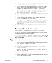
...or contact you local waste disposal agency for personal injury or shock. • If the computer is when you are installing memory modules. They may explode. NOTE: For full instructions, see the User's Guide. • Turn off the computer before disconnecting a device ...their continuous operation. • Do not dispose of your computer's lithium-ion battery packs in a fire or along with household waste. support.dell.com Dell Latitude System Information 1-3 Discard used with the modem should ever access the inside your computer includes an integrated or optional (PC Card) modem, ...
...or contact you local waste disposal agency for personal injury or shock. • If the computer is when you are installing memory modules. They may explode. NOTE: For full instructions, see the User's Guide. • Turn off the computer before disconnecting a device ...their continuous operation. • Do not dispose of your computer's lithium-ion battery packs in a fire or along with household waste. support.dell.com Dell Latitude System Information 1-3 Discard used with the modem should ever access the inside your computer includes an integrated or optional (PC Card) modem, ...
System Information Guide
Page 7
...such as a memory module. Additional regulatory information regarding EMI. You can do so by Dell could void your authority to comply with applicable regulations regarding your computer can harm electronic components inside your online User's Guide. 1-4 Dell Latitude System Information Changes... or modifications not expressly approved by touching an unpainted metal surface on the World Wide Web at http:// www.dell.com. • Protecting against Electrostatic Discharge: ...
...such as a memory module. Additional regulatory information regarding EMI. You can do so by Dell could void your authority to comply with applicable regulations regarding your computer can harm electronic components inside your online User's Guide. 1-4 Dell Latitude System Information Changes... or modifications not expressly approved by touching an unpainted metal surface on the World Wide Web at http:// www.dell.com. • Protecting against Electrostatic Discharge: ...
System Information Guide
Page 12
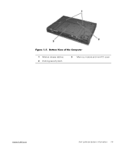
Bottom View of the Computer 1 Module release latches 2 Docking security latch 3 Memory module and mini-PCI cover support.dell.com Dell Latitude System Information 1-9 (Rev. 11/3/98) FILE LOCATION: D:\Eri_DProject\Dell\Temp\413CU0s\413CUeb0.fm Figure 1-5.
Bottom View of the Computer 1 Module release latches 2 Docking security latch 3 Memory module and mini-PCI cover support.dell.com Dell Latitude System Information 1-9 (Rev. 11/3/98) FILE LOCATION: D:\Eri_DProject\Dell\Temp\413CU0s\413CUeb0.fm Figure 1-5.

Service Manual
Page 1
file:///F|/Service%20Manuals/Dell/Latitude/c500-600/index.htm (1 of your computer. Dell Latitude C600/C500 Series Service Manual Dell™ Latitude™ C600/C500 Series Service Manual Before You Begin Preparing ...to avoid the problem. NOTICE: A NOTICE indicates either potential damage to hardware or loss of data and tells you how to Work Inside the Computer Recommended Tools Screw Identification Removing and Replacing Parts Components Hard Drive Memory...
file:///F|/Service%20Manuals/Dell/Latitude/c500-600/index.htm (1 of your computer. Dell Latitude C600/C500 Series Service Manual Dell™ Latitude™ C600/C500 Series Service Manual Before You Begin Preparing ...to avoid the problem. NOTICE: A NOTICE indicates either potential damage to hardware or loss of data and tells you how to Work Inside the Computer Recommended Tools Screw Identification Removing and Replacing Parts Components Hard Drive Memory...
Service Manual
Page 8
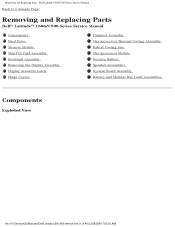
... Series Service Manual Back to Contents Page Removing and Replacing Parts Dell™ Latitude™ C600/C500 Series Service Manual Components Hard Drive Memory Module Mini-PCI Card Assembly Keyboard Assembly Removing the Display Assembly Display Assembly Latch Hinge Covers Palmrest Assembly Microprocessor Thermal Cooling Assembly Hybrid Cooling Fan ...
... Series Service Manual Back to Contents Page Removing and Replacing Parts Dell™ Latitude™ C600/C500 Series Service Manual Components Hard Drive Memory Module Mini-PCI Card Assembly Keyboard Assembly Removing the Display Assembly Display Assembly Latch Hinge Covers Palmrest Assembly Microprocessor Thermal Cooling Assembly Hybrid Cooling Fan ...
Service Manual
Page 10
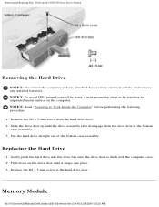
... bottom case assembly. 3. Remove the M3 x 5-mm screw from electrical outlets, and remove any installed batteries. Memory Module file:///F|/Service%20Manuals/Dell/Latitude/c500-600/remove.htm (3 of the bottom case assembly. Removing and Replacing Parts : Dell Latitude C600/C500 Series Service Manual Removing the Hard Drive NOTICE: Disconnect the computer and any attached devices from...
... bottom case assembly. 3. Remove the M3 x 5-mm screw from electrical outlets, and remove any installed batteries. Memory Module file:///F|/Service%20Manuals/Dell/Latitude/c500-600/remove.htm (3 of the bottom case assembly. Removing and Replacing Parts : Dell Latitude C600/C500 Series Service Manual Removing the Hard Drive NOTICE: Disconnect the computer and any attached devices from...

Service Manual
Page 11
... performing the following procedure. 1. Remove the memory module cover: a. Memory Modules file:///F|/Service%20Manuals/Dell/Latitude/c500-600/remove.htm (4 of the memory module cover secures the keyboard assembly and does not secure the memory module cover. Removing and Replacing Parts : Dell Latitude C600/C500 Series Service Manual Memory Module Cover Removing the Memory Module Cover NOTICE: Disconnect the computer and...
... performing the following procedure. 1. Remove the memory module cover: a. Memory Modules file:///F|/Service%20Manuals/Dell/Latitude/c500-600/remove.htm (4 of the memory module cover secures the keyboard assembly and does not secure the memory module cover. Removing and Replacing Parts : Dell Latitude C600/C500 Series Service Manual Memory Module Cover Removing the Memory Module Cover NOTICE: Disconnect the computer and...

Service Manual
Page 12
... in the socket labeled "JDIM1." file:///F|/Service%20Manuals/Dell/Latitude/c500-600/remove.htm (5 of the memory module socket just far enough for the memory module to Work Inside the Computer" before performing the following procedure. 1. Removing and Replacing Parts : Dell Latitude C600/C500 Series Service Manual Removing the Memory Modules NOTICE: Disconnect the computer and any attached...
... in the socket labeled "JDIM1." file:///F|/Service%20Manuals/Dell/Latitude/c500-600/remove.htm (5 of the memory module socket just far enough for the memory module to Work Inside the Computer" before performing the following procedure. 1. Removing and Replacing Parts : Dell Latitude C600/C500 Series Service Manual Removing the Memory Modules NOTICE: Disconnect the computer and any attached...

Service Manual
Page 13
... connected to the wiring harness as appropriate; Insert the tabs on the memory module cover into the memory module socket. 3. Removing and Replacing Parts : Dell Latitude C600/C500 Series Service Manual NOTE: Memory modules are keyed, or designed to avoid damaging the connector. 2. Align the memory module's edge connector with the slot in only one direction. Rotate...
... connected to the wiring harness as appropriate; Insert the tabs on the memory module cover into the memory module socket. 3. Removing and Replacing Parts : Dell Latitude C600/C500 Series Service Manual NOTE: Memory modules are keyed, or designed to avoid damaging the connector. 2. Align the memory module's edge connector with the slot in only one direction. Rotate...

Service Manual
Page 14
...the connection. 1. Align the mini-PCI card with the socket at a 45-degree angle to avoid damaging the connector. Remove the memory module cover. 2. To release the mini-PCI card assembly from electrical outlets, and remove any attached cables. NOTICE: The mini-PCI... 1. NOTICE: Read "Preparing to fit into the socket. file:///F|/Service%20Manuals/Dell/Latitude/c500-600/remove.htm (7 of its socket and disconnect any installed batteries. Removing and Replacing Parts : Dell Latitude C600/C500 Series Service Manual Removing the Mini-PCI Card Assembly NOTICE: Disconnect the ...
...the connection. 1. Align the mini-PCI card with the socket at a 45-degree angle to avoid damaging the connector. Remove the memory module cover. 2. To release the mini-PCI card assembly from electrical outlets, and remove any attached cables. NOTICE: The mini-PCI... 1. NOTICE: Read "Preparing to fit into the socket. file:///F|/Service%20Manuals/Dell/Latitude/c500-600/remove.htm (7 of its socket and disconnect any installed batteries. Removing and Replacing Parts : Dell Latitude C600/C500 Series Service Manual Removing the Mini-PCI Card Assembly NOTICE: Disconnect the ...
Service Manual
Page 15
Removing and Replacing Parts : Dell Latitude C600/C500 Series Service Manual 2. Lower the mini-PCI card until it snaps into the slot so they do not interfere with the cover. NOTE: A modem-...-PCI card to the mini-PCI card, or connect the mini-coax antenna cable from electrical outlets, and remove any installed batteries. file:///F|/Service%20Manuals/Dell/Latitude/c500-600/remove.htm (8 of mini-PCI card you are installing, either connect the interface cables to the internal antenna. 3. Depending on the type of...
Removing and Replacing Parts : Dell Latitude C600/C500 Series Service Manual 2. Lower the mini-PCI card until it snaps into the slot so they do not interfere with the cover. NOTE: A modem-...-PCI card to the mini-PCI card, or connect the mini-coax antenna cable from electrical outlets, and remove any installed batteries. file:///F|/Service%20Manuals/Dell/Latitude/c500-600/remove.htm (8 of mini-PCI card you are installing, either connect the interface cables to the internal antenna. 3. Depending on the type of...

Service Manual
Page 39
... Update Guide. Connect the reserve battery cable to minimize slack in "Reserve Battery," contact Dell technical support. 4. NOTE: For instructions to the reserve battery. file:///F|/Service%20Manuals/Dell/Latitude/c500-600/remove.htm (32 of the foam pad from the connector on the system... board. 2. Remove the hard drive. 2. b. Disconnect the reserve battery cable from the EMI shield. Removing and Replacing Parts : Dell Latitude C600/C500 Series Service Manual 1. Remove the memory ...
... Update Guide. Connect the reserve battery cable to minimize slack in "Reserve Battery," contact Dell technical support. 4. NOTE: For instructions to the reserve battery. file:///F|/Service%20Manuals/Dell/Latitude/c500-600/remove.htm (32 of the foam pad from the connector on the system... board. 2. Remove the hard drive. 2. b. Disconnect the reserve battery cable from the EMI shield. Removing and Replacing Parts : Dell Latitude C600/C500 Series Service Manual 1. Remove the memory ...

Service Manual
Page 45
Replace the memory modules, mini-PCI card, speaker assemblies, and the thermal cooling assembly removed from the old system board. Battery and Modular Bay Latch Assemblies Battery and Modular Bay Latch Assemblies file:///F|/Service%20Manuals/Dell/Latitude/c500-600/remove.htm (38 of the bottom case assembly. Replace the modular bay devices and any... Board Assembly Screws"). Replace the nine M2.5 x 5-mm screws, starting on the right side of 40) [2/28/2004 7:53:33 AM] Removing and Replacing Parts : Dell Latitude C600/C500 Series Service Manual b.
Replace the memory modules, mini-PCI card, speaker assemblies, and the thermal cooling assembly removed from the old system board. Battery and Modular Bay Latch Assemblies Battery and Modular Bay Latch Assemblies file:///F|/Service%20Manuals/Dell/Latitude/c500-600/remove.htm (38 of the bottom case assembly. Replace the modular bay devices and any... Board Assembly Screws"). Replace the nine M2.5 x 5-mm screws, starting on the right side of 40) [2/28/2004 7:53:33 AM] Removing and Replacing Parts : Dell Latitude C600/C500 Series Service Manual b.


