

Brocade 6505 Hardware Reference Manual
Page 4
... Fans In this chapter 27 Introduction 27 Removing and replacing a power supply and fan assembly 27 Determining the need to replace a power supply and fan assembly 29 Time required 30 Items required 30 Removing a power supply and fan assembly 30 Replacing a power supply and fan assembly 31 Brocade 6505 Specifications In this appendix 33 Weight and physical dimensions 33 Facility...
... Fans In this chapter 27 Introduction 27 Removing and replacing a power supply and fan assembly 27 Determining the need to replace a power supply and fan assembly 29 Time required 30 Items required 30 Removing a power supply and fan assembly 30 Replacing a power supply and fan assembly 31 Brocade 6505 Specifications In this appendix 33 Weight and physical dimensions 33 Facility...

Brocade 6505 Hardware Reference Manual
Page 7
... of Power Supplies and Fans" provides procedures for removing and replacing the field-replaceable units (FRUs). • Appendix A, "Brocade 6505 Specifications" provides tables of the switch. • Chapter 2, "Brocade 6505 Installation and Configuration" provides the information needed to install the switch in your network. • Chapter 3, "Brocade 6505 Operation" discusses the day-to the Brocade 6505 running Brocade Fabric OS version 7.0.1. Brocade 6505...
... of Power Supplies and Fans" provides procedures for removing and replacing the field-replaceable units (FRUs). • Appendix A, "Brocade 6505 Specifications" provides tables of the switch. • Chapter 2, "Brocade 6505 Installation and Configuration" provides the information needed to install the switch in your network. • Chapter 3, "Brocade 6505 Operation" discusses the day-to the Brocade 6505 running Brocade Fabric OS version 7.0.1. Brocade 6505...

Brocade 6505 Hardware Reference Manual
Page 13
... POD license can also be purchased. The base model also offers a single power supply and fan module with interoperability and ease-of-use advantages. You can increase the number of hosts that have access to the host and the fabric. The Brocade 6505 supplies Reliability, Availability, and Serviceability (RAS) performance and the scalability requirements of...
... POD license can also be purchased. The base model also offers a single power supply and fan module with interoperability and ease-of-use advantages. You can increase the number of hosts that have access to the host and the fabric. The Brocade 6505 supplies Reliability, Availability, and Serviceability (RAS) performance and the scalability requirements of...

Brocade 6505 Hardware Reference Manual
Page 15
..., and the Fibre Channel ports and corresponding port status LEDs. Port side of the Brocade 6505 The port side of the Brocade 6505. A second assembly is available for configuration uploads and downloads. • One power supply and fan assembly in the base model. Brocade 6505 Hardware Reference Manual 3 53-1002449-01 There are two fans per FC port...
..., and the Fibre Channel ports and corresponding port status LEDs. Port side of the Brocade 6505 The port side of the Brocade 6505. A second assembly is available for configuration uploads and downloads. • One power supply and fan assembly in the base model. Brocade 6505 Hardware Reference Manual 3 53-1002449-01 There are two fans per FC port...

Brocade 6505 Hardware Reference Manual
Page 16
... 2 shows the nonport side of the Brocade 6505, which contains the power supply (including the AC power receptacle and AC power switch) and fan assemblies. 1 Nonport side of the Brocade 6505 123 4 567 8 1 System status LED 5 System power LED 2 Management Ethernet port with plug retainer) 6 Captive screw 7 Handle FIGURE 2 Nonport side of the Brocade 6505 4 Brocade 6505 Hardware Reference Manual 53-1002449-01
... 2 shows the nonport side of the Brocade 6505, which contains the power supply (including the AC power receptacle and AC power switch) and fan assemblies. 1 Nonport side of the Brocade 6505 123 4 567 8 1 System status LED 5 System power LED 2 Management Ethernet port with plug retainer) 6 Captive screw 7 Handle FIGURE 2 Nonport side of the Brocade 6505 4 Brocade 6505 Hardware Reference Manual 53-1002449-01

Brocade 6505 Hardware Reference Manual
Page 17
... - The optional mid-mount rack kit for switches. When you open the Brocade 6505 packaging, verify that no damage has occurred during shipping: • The Brocade 6505 switch, containing one combined power supply and fan assembly • 16 Gbps or 8 Gbps SFP+ modules for the Fibre Channel ports (speed and quantity as a standalone unit - The rack...
... - The optional mid-mount rack kit for switches. When you open the Brocade 6505 packaging, verify that no damage has occurred during shipping: • The Brocade 6505 switch, containing one combined power supply and fan assembly • 16 Gbps or 8 Gbps SFP+ modules for the Fibre Channel ports (speed and quantity as a standalone unit - The rack...

Brocade 6505 Hardware Reference Manual
Page 18
... inches) wide. • The two rack kit options for the Brocade 6505 use rails that are met: • At a minimum, adequate cooling requires that you install the switch with local electrical codes. • The supply circuit, line fusing, and wire size are adequate, as an earthquake...requirements are slimmer than standard rails to a branch circuit, such as a power strip. • Airflow and temperature requirements are met on the switch nameplate. • The power supply standards provided in Table 7, "System power specifications" are met: • The cabinet must be bent under no ...
... inches) wide. • The two rack kit options for the Brocade 6505 use rails that are met: • At a minimum, adequate cooling requires that you install the switch with local electrical codes. • The supply circuit, line fusing, and wire size are adequate, as an earthquake...requirements are slimmer than standard rails to a branch circuit, such as a power strip. • Airflow and temperature requirements are met on the switch nameplate. • The power supply standards provided in Table 7, "System power specifications" are met: • The cabinet must be bent under no ...

Brocade 6505 Hardware Reference Manual
Page 20
... the switch to set the IP address, see "Brocade 6505 configuration." For instructions on the power supplies by flipping both AC switches to avoid stress. 2. Power on how to the network until power-on . 3. See the EZSwitchSetup CD, included with the Brocade 6505, for a Brocade 6505 4. After POST is correctly set up the Brocade 6505 in a single-switch setup, you are green...
... the switch to set the IP address, see "Brocade 6505 configuration." For instructions on the power supplies by flipping both AC switches to avoid stress. 2. Power on how to the network until power-on . 3. See the EZSwitchSetup CD, included with the Brocade 6505, for a Brocade 6505 4. After POST is correctly set up the Brocade 6505 in a single-switch setup, you are green...
Brocade 6505 Hardware Reference Manual
Page 25
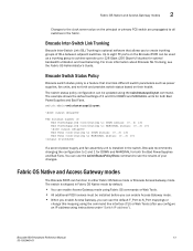
... to eight FC ports on the Brocade 6505 can enable Access Gateway mode using the switchstatuspolicyset command. The switch status policy configuration can be updated using Fabric OS commands or Web Tools. • All additional POD licenses must be used as power supplies, fan units, and so forth ...and provides switch status based on the principal or primary FCS switch are propagated to see the Fabric OS Administrator's Guide. Fabric OS Native and Access Gateway modes The Brocade 6505 can enable Access Gateway mode. ...
... to eight FC ports on the Brocade 6505 can enable Access Gateway mode using the switchstatuspolicyset command. The switch status policy configuration can be updated using Fabric OS commands or Web Tools. • All additional POD licenses must be used as power supplies, fan units, and so forth ...and provides switch status based on the principal or primary FCS switch are propagated to see the Fabric OS Administrator's Guide. Fabric OS Native and Access Gateway modes The Brocade 6505 can enable Access Gateway mode. ...

Brocade 6505 Hardware Reference Manual
Page 29
... powered on ; Set the AC power switches to shutdown the switch [y/n]? Brocade 6505 Operation Chapter 3 In this chapter •Powering the Brocade 6505 on and off 17 •LED activity interpretation 18 •POST and boot specifications 21 •Interpreting POST results 22 •Brocade 6505 maintenance 23 •Brocade 6505 management 25 Powering the Brocade 6505 on and off the Brocade 6505. 1. Power is supplied to the power...
... powered on ; Set the AC power switches to shutdown the switch [y/n]? Brocade 6505 Operation Chapter 3 In this chapter •Powering the Brocade 6505 on and off 17 •LED activity interpretation 18 •POST and boot specifications 21 •Interpreting POST results 22 •Brocade 6505 maintenance 23 •Brocade 6505 management 25 Powering the Brocade 6505 on and off the Brocade 6505. 1. Power is supplied to the power...

Brocade 6505 Hardware Reference Manual
Page 30
... of the FC ports. 18 Brocade 6505 Hardware Reference Manual 53-1002449-01 LED locations Figure 3 shows the LEd locations on the non-port side of the switch. The LED colors are arrayed above each pair of Fibre Channel ports. • One power supply and fan assembly LED above the... These LEDs are either of the colors during boot, POST, or other diagnostic tests. The port status LEDs for each power supply on the port side of the Brocade 6505. There are complete. Refer to the upper and lower ports respectively in each pair. 3 LED activity interpretation LED activity ...
... of the FC ports. 18 Brocade 6505 Hardware Reference Manual 53-1002449-01 LED locations Figure 3 shows the LEd locations on the non-port side of the switch. The LED colors are arrayed above each pair of Fibre Channel ports. • One power supply and fan assembly LED above the... These LEDs are either of the colors during boot, POST, or other diagnostic tests. The port status LEDs for each power supply on the port side of the Brocade 6505. There are complete. Refer to the upper and lower ports respectively in each pair. 3 LED activity interpretation LED activity ...

Brocade 6505 Hardware Reference Manual
Page 32
...exceeded. There is link activity (traffic). There is a link. No action required. 20 Brocade 6505 Hardware Reference Manual 53-1002449-01 System is required. this status, including a single power supply failure, a fan failure, or one or more than five seconds) System is off or ... System Status (bicolor) No light Steady green Steady amber (for details on (power supply switches to I), the power cables are functioning properly. Check the failure indicated on the nonport side of Brocade 6505 LED patterns Table 1 describes the port side LEDs and their behavior. Port speed...
...exceeded. There is link activity (traffic). There is a link. No action required. 20 Brocade 6505 Hardware Reference Manual 53-1002449-01 System is required. this status, including a single power supply failure, a fan failure, or one or more than five seconds) System is off or ... System Status (bicolor) No light Steady green Steady amber (for details on (power supply switches to I), the power cables are functioning properly. Check the failure indicated on the nonport side of Brocade 6505 LED patterns Table 1 describes the port side LEDs and their behavior. Port speed...
Brocade 6505 Hardware Reference Manual
Page 33
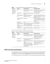
... that the diagnostic tests are not being run. Verify the power supply and fan assembly is on self-test (POST). POST can be omitted after subsequent reboots by (2 sec) portDisable command). Brocade 6505 Hardware Reference Manual 21 53-1002449-01 Re-enable the port... using the fastboot command or entering the diagDisablePost command to persistently disable POST. Check the power cable connection. Power supply and fan assembly is turned on or ...
... that the diagnostic tests are not being run. Verify the power supply and fan assembly is on self-test (POST). POST can be omitted after subsequent reboots by (2 sec) portDisable command). Brocade 6505 Hardware Reference Manual 21 53-1002449-01 Re-enable the port... using the fastboot command or entering the diagDisablePost command to persistently disable POST. Check the power cable connection. Power supply and fan assembly is turned on or ...

Brocade 6505 Hardware Reference Manual
Page 39
...to left on page 5 before servicing. Even though they are identified as displayed in each power supply and fan assembly. The field-replaceable units (FRUs) in the Brocade 6505 can continue operating during the FRU replacement if the conditions specified in the procedure are identified ... from right to cool the entire system. The base model Brocade 6505 has one power supply and fan assembly, as Power Supply Unit:1 and Fan Unit:1. In the chassisShow command they are contained within a single unit, the power supply and fan components are followed. The system software sets fan...
...to left on page 5 before servicing. Even though they are identified as displayed in each power supply and fan assembly. The field-replaceable units (FRUs) in the Brocade 6505 can continue operating during the FRU replacement if the conditions specified in the procedure are identified ... from right to cool the entire system. The base model Brocade 6505 has one power supply and fan assembly, as Power Supply Unit:1 and Fan Unit:1. In the chassisShow command they are contained within a single unit, the power supply and fan components are followed. The system software sets fan...

Brocade 6505 Hardware Reference Manual
Page 40
.... There are using only one power supply and fan assembly fails, leave the power supply and fan assembly in the Brocade 6505 until it can be sure that power supply fails, the switch will turn off switch 5 Power plug receptacle (with plug retainer) 6 Thumbscrew 7 Handle FIGURE 7 Nonport side of the Brocade 6505 CAUTION Disassembling any . 28 Brocade 6505 Hardware Reference Manual 53-1002449...
.... There are using only one power supply and fan assembly fails, leave the power supply and fan assembly in the Brocade 6505 until it can be sure that power supply fails, the switch will turn off switch 5 Power plug receptacle (with plug retainer) 6 Thumbscrew 7 Handle FIGURE 7 Nonport side of the Brocade 6505 CAUTION Disassembling any . 28 Brocade 6505 Hardware Reference Manual 53-1002449...

Brocade 6505 Hardware Reference Manual
Page 41
... of the following : • Check the power cable connection. • Verify that the power supply and fan assembly is on /off • The power supply and fan assembly has failed NOTE: When the Brocade 6505 is operating normally. Determining the need to replace a power supply and fan assembly Use one of the power supply and fan assembly: br6505:admin> fanshow Fan...
... of the following : • Check the power cable connection. • Verify that the power supply and fan assembly is on /off • The power supply and fan assembly has failed NOTE: When the Brocade 6505 is operating normally. Determining the need to replace a power supply and fan assembly Use one of the power supply and fan assembly: br6505:admin> fanshow Fan...

Brocade 6505 Hardware Reference Manual
Page 42
... Figure 8 for at least four seconds and has a steady green LED. 2. 4 Removing and replacing a power supply and fan assembly POWER SUPPLY Unit: 1 Power Source: Time Awake: AC 0 days Power Supply #1 is OK Power Supply #2 is being replaced) has been powered on the assembly just removed. 30 Brocade 6505 Hardware Reference Manual 53-1002449-01 Complete the following items are required to replace...
... Figure 8 for at least four seconds and has a steady green LED. 2. 4 Removing and replacing a power supply and fan assembly POWER SUPPLY Unit: 1 Power Source: Time Awake: AC 0 days Power Supply #1 is OK Power Supply #2 is being replaced) has been powered on the assembly just removed. 30 Brocade 6505 Hardware Reference Manual 53-1002449-01 Complete the following items are required to replace...

Brocade 6505 Hardware Reference Manual
Page 43
.... CAUTION Do not force the installation. Removing and replacing a power supply and fan assembly 4 1 2 3 4 1 Brocade 6505 chassis 2 Power supply and fan assembly 3 Captive screw 4 Product labels FIGURE 8 Inserting the power supply and fan assembly into the switch Replacing a power supply and fan assembly Refer to the switch could result if a live power supply is correctly oriented before continuing. If the FRU does...
.... CAUTION Do not force the installation. Removing and replacing a power supply and fan assembly 4 1 2 3 4 1 Brocade 6505 chassis 2 Power supply and fan assembly 3 Captive screw 4 Product labels FIGURE 8 Inserting the power supply and fan assembly into the switch Replacing a power supply and fan assembly Refer to the switch could result if a live power supply is correctly oriented before continuing. If the FRU does...

Brocade 6505 Hardware Reference Manual
Page 44
... chassis until it is firmly seated. 4. Gently push the power supply and fan assembly into the power supply and fan assembly and power on the new power supply and fan assembly displays a steady green light while the Brocade 6505 is securely installed and seated properly. 7. Optionally, if using the Web Tools application. 32 Brocade 6505 Hardware Reference Manual 53-1002449-01
... chassis until it is firmly seated. 4. Gently push the power supply and fan assembly into the power supply and fan assembly and power on the new power supply and fan assembly displays a steady green light while the Brocade 6505 is securely installed and seated properly. 7. Optionally, if using the Web Tools application. 32 Brocade 6505 Hardware Reference Manual 53-1002449-01

Brocade 6505 Hardware Reference Manual
Page 45
... which requires a slim rail rack mount kit for mounting) Weight (with one power supply and fan assembly, and no 7.82 kg (17.25 lb) SFP+ transceivers installed) Facility requirements Table 6 provides the facilities requirements that must be met for the Brocade 6505. Brocade 6505 Specifications Appendix A In this appendix •Weight and physical dimensions 33 •...
... which requires a slim rail rack mount kit for mounting) Weight (with one power supply and fan assembly, and no 7.82 kg (17.25 lb) SFP+ transceivers installed) Facility requirements Table 6 provides the facilities requirements that must be met for the Brocade 6505. Brocade 6505 Specifications Appendix A In this appendix •Weight and physical dimensions 33 •...


