Manual
Page 3
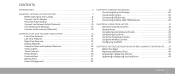
...Alienware Command Center 32 Stealth Mode 32 Using Removable Media and Cards 32 Using the Optical Drive 33 Using the Integrated Camera 33 Using the Wireless Control 33 Configuring the BIOS 34 CHAPTER 5: INSTALLING ADDITIONAL OR REPLACEMENT COMPONENTS . . . . . 41 Before You Begin 42 Replacing the Battery Pack 44 Upgrading or Replacing... Memory 45 Upgrading or Replacing the Hard Drive 47 CONTENTS 3
...Alienware Command Center 32 Stealth Mode 32 Using Removable Media and Cards 32 Using the Optical Drive 33 Using the Integrated Camera 33 Using the Wireless Control 33 Configuring the BIOS 34 CHAPTER 5: INSTALLING ADDITIONAL OR REPLACEMENT COMPONENTS . . . . . 41 Before You Begin 42 Replacing the Battery Pack 44 Upgrading or Replacing... Memory 45 Upgrading or Replacing the Hard Drive 47 CONTENTS 3

Manual
Page 43
...your computer and all telephone or network cables from your computer (for more information, see the Regulatory Compliance Homepage at www.dell.com/regulatory_compliance. Also, before you connect a cable, ensure that the work surface is connected to prevent the computer cover ...their electrical outlets. Disconnect all attached devices from being scratched. 2. Remove the battery from the ExpressCard slot and the Media Card slot. 6. For additional safety best practices information, see "Replacing the Battery Pack" on a card. Do not touch the components or contacts on page...
...your computer and all telephone or network cables from your computer (for more information, see the Regulatory Compliance Homepage at www.dell.com/regulatory_compliance. Also, before you connect a cable, ensure that the work surface is connected to prevent the computer cover ...their electrical outlets. Disconnect all attached devices from being scratched. 2. Remove the battery from the ExpressCard slot and the Media Card slot. 6. For additional safety best practices information, see "Replacing the Battery Pack" on a card. Do not touch the components or contacts on page...
Manual
Page 44
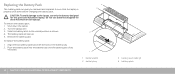
... battery pack. Slide the battery latch to the laptop, use batteries designed for this particular Alienware laptop. Do not use only the battery designed for other Alienware or Dell laptops. The battery pack will pop up. 5. Push the battery pack into the battery bay until the battery pack clicks into place. 4 3 2 1 1 battery latch 2 battery bay 44 CHAPTER 5: INSTALLING ADDITIONAL OR REPLACEMENT COMPONENTS 3 battery pack tabs (2) 4 battery...
... battery pack. Slide the battery latch to the laptop, use batteries designed for this particular Alienware laptop. Do not use only the battery designed for other Alienware or Dell laptops. The battery pack will pop up. 5. Push the battery pack into the battery bay until the battery pack clicks into place. 4 3 2 1 1 battery latch 2 battery bay 44 CHAPTER 5: INSTALLING ADDITIONAL OR REPLACEMENT COMPONENTS 3 battery pack tabs (2) 4 battery...
Manual
Page 57
..., see "Upgrading or Replacing Memory" on page 45). • Computers using the AC adapter, and then turn on the computer. The computer may be depleted. Connect the computer to your computer. Reseat the memory modules if applicable (see "CONTACTING ALIENWARE" on page 73). ...that memory modules be in pairs. CHAPTER 6: TROUBLESHOOTING 57 Test the electrical outlet: Ensure that requires a higher resolution than your computer, the battery charge may be installed in a power saving mode: Press a key on . Switch the video image: If your computer is recommended that...
..., see "Upgrading or Replacing Memory" on page 45). • Computers using the AC adapter, and then turn on the computer. The computer may be depleted. Connect the computer to your computer. Reseat the memory modules if applicable (see "CONTACTING ALIENWARE" on page 73). ...that memory modules be in pairs. CHAPTER 6: TROUBLESHOOTING 57 Test the electrical outlet: Ensure that requires a higher resolution than your computer, the battery charge may be installed in a power saving mode: Press a key on . Switch the video image: If your computer is recommended that...

Manual
Page 72
...Replacement Components or Accessories It is only advised to severe mechanical shocks. Careless handling of the computer does not occur when the operating instructions are followed. Mechanical Shock is nothing to worry about. Your computer protects itself against most irregularities in the power source. When You Should Contact Alienware • The battery...is not covered by Alienware. 72 APPENDIX A: GENERAL AND ELECTRICAL SAFETY PRECAUTIONS General Safety Precautions • Mechanical Shock: Your computer should never be subjected to use replacement parts or accessories ...
...Replacement Components or Accessories It is only advised to severe mechanical shocks. Careless handling of the computer does not occur when the operating instructions are followed. Mechanical Shock is nothing to worry about. Your computer protects itself against most irregularities in the power source. When You Should Contact Alienware • The battery...is not covered by Alienware. 72 APPENDIX A: GENERAL AND ELECTRICAL SAFETY PRECAUTIONS General Safety Precautions • Mechanical Shock: Your computer should never be subjected to use replacement parts or accessories ...

Service Manual
Page 3
... 7 Turning Off Your Computer 7 Before Working Inside Your Computer 8 CHAPTER 2: BATTERY PACK 9 Removing the Battery Pack 11 Replacing the Battery Pack 11 CHAPTER 3: COMPARTMENT DOOR 12 Removing the Compartment Door 14 Replacing the Compartment Door 14 CHAPTER 4: HARD DRIVE 15 Removing the Hard Drive 17 Replacing the Hard Drive 18 CHAPTER 5: MEMORY MODULE(S 19 Removing the...
... 7 Turning Off Your Computer 7 Before Working Inside Your Computer 8 CHAPTER 2: BATTERY PACK 9 Removing the Battery Pack 11 Replacing the Battery Pack 11 CHAPTER 3: COMPARTMENT DOOR 12 Removing the Compartment Door 14 Replacing the Compartment Door 14 CHAPTER 4: HARD DRIVE 15 Removing the Hard Drive 17 Replacing the Hard Drive 18 CHAPTER 5: MEMORY MODULE(S 19 Removing the...
Service Manual
Page 5
... Drive 99 CHAPTER 22: SYSTEM BOARD 100 Removing the System Board 102 Replacing the System Board 104 CHAPTER 23: SPEAKERS 105 Removing the Speakers 107 Replacing the Speakers 107 CHAPTER 24: BATTERY LATCH ASSEMBLY 108 Removing the Battery Latch Assembly 110 Replacing the Battery Latch Assembly 110 CHAPTER 25: SYSTEM SETUP 111 Overview 112 Entering System...
... Drive 99 CHAPTER 22: SYSTEM BOARD 100 Removing the System Board 102 Replacing the System Board 104 CHAPTER 23: SPEAKERS 105 Removing the Speakers 107 Replacing the Speakers 107 CHAPTER 24: BATTERY LATCH ASSEMBLY 108 Removing the Battery Latch Assembly 110 Replacing the Battery Latch Assembly 110 CHAPTER 25: SYSTEM SETUP 111 Overview 112 Entering System...
Service Manual
Page 11
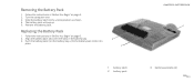
Remove the battery pack. Push the battery pack into the battery bay until the battery pack clicks into place. 3 2 1 battery latch 2 battery pack CHAPTER 2: BATTERY PACK 1 3 battery pack tabs (2) 011 /011 Removing the Battery Pack 1. Follow the instructions in "Before You Begin" on page 6. 2. The battery pack will pop up. 5. Follow the instructions in the battery bay. 3. Turn the computer over. 3. Align the battery pack tabs with the slots in "Before You Begin" on page 6. 2. Slide the battery latch to the unlock position as shown. 4. Replacing the Battery Pack 1.
Remove the battery pack. Push the battery pack into the battery bay until the battery pack clicks into place. 3 2 1 battery latch 2 battery pack CHAPTER 2: BATTERY PACK 1 3 battery pack tabs (2) 011 /011 Removing the Battery Pack 1. Follow the instructions in "Before You Begin" on page 6. 2. The battery pack will pop up. 5. Follow the instructions in the battery bay. 3. Turn the computer over. 3. Align the battery pack tabs with the slots in "Before You Begin" on page 6. 2. Slide the battery latch to the unlock position as shown. 4. Replacing the Battery Pack 1.
Service Manual
Page 14
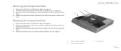
... of the computer 2 compartment door 3 screws (2) 014 /014 Slide the compartment door towards the back of the computer and then lift it up. Replace the battery pack (see "Removing the Battery Pack" on page 6. 2. Remove the battery pack (see "Replacing the Battery Pack" on the computer base and slide it towards the front of the computer...
... of the computer 2 compartment door 3 screws (2) 014 /014 Slide the compartment door towards the back of the computer and then lift it up. Replace the battery pack (see "Removing the Battery Pack" on page 6. 2. Remove the battery pack (see "Replacing the Battery Pack" on the computer base and slide it towards the front of the computer...

Service Manual
Page 18
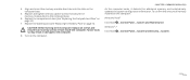
...018 /018 Connect the interposer to slide the drive into place. Place the hard-drive assembly in the hard-drive bracket. 5. Replace the compartment door (see "Replacing the Battery Pack" on page 14). 9. Failure to the hard-drive bay. 8. Install the drivers and utilities for your computer, as needed...4. Follow the instructions in damage to the hard-drive bracket. 6. Place the hard drive in the hard-drive bay. 7. Replace the battery pack (see "Replacing the Compartment Door" on page 11). Align and tighten the four captive screws that secure the hard drive to the computer. ...
...018 /018 Connect the interposer to slide the drive into place. Place the hard-drive assembly in the hard-drive bracket. 5. Replace the compartment door (see "Replacing the Battery Pack" on page 14). 9. Failure to the hard-drive bay. 8. Install the drivers and utilities for your computer, as needed...4. Follow the instructions in damage to the hard-drive bracket. 6. Place the hard drive in the hard-drive bay. 7. Replace the battery pack (see "Replacing the Compartment Door" on page 11). Align and tighten the four captive screws that secure the hard drive to the computer. ...
Service Manual
Page 24
Replace the battery pack (see "Replacing the Compartment Door" on the computer base. 5. CHAPTER 5: MEMORY MODULE(S) As the computer boots, it detects the additional memory and automatically updates the system configuration ... screws and ensure that secure the memory-module door to the computer. 8. 4. Replace and tighten the two captive screws that no stray screws remain inside the computer. Replace the compartment door (see "Replacing the Battery Pack" on the computer. To confirm the amount of memory installed in damage to the computer base. 6. Failure to...
Replace the battery pack (see "Replacing the Compartment Door" on the computer base. 5. CHAPTER 5: MEMORY MODULE(S) As the computer boots, it detects the additional memory and automatically updates the system configuration ... screws and ensure that secure the memory-module door to the computer. 8. 4. Replace and tighten the two captive screws that no stray screws remain inside the computer. Replace the compartment door (see "Replacing the Battery Pack" on the computer. To confirm the amount of memory installed in damage to the computer base. 6. Failure to...
Service Manual
Page 27
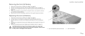
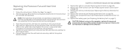
... computer base, use a plastic scribe to pry it to the computer base. 4. Replacing the Coin-Cell Battery 1. Follow the instructions in "Before You Begin" on page 11). Replace the battery pack (see "Replacing the Compartment Door" on page 6. 2. Replace the compartment door (see "Replacing the Battery Pack" on page 6. 2. Follow the instructions in damage to the system board...
... computer base, use a plastic scribe to pry it to the computer base. 4. Replacing the Coin-Cell Battery 1. Follow the instructions in "Before You Begin" on page 11). Replace the battery pack (see "Replacing the Compartment Door" on page 6. 2. Replace the compartment door (see "Replacing the Battery Pack" on page 6. 2. Follow the instructions in damage to the system board...
Service Manual
Page 31
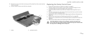
... cable from the center control cover connector. 11. Release the connector latch to the computer base. 5. Replace the memory module(s) (see "Replacing the Battery Pack" on page 6. 2. Follow the instructions in place. 4. Turn the computer over and replace the two screws that no stray screws remain inside the computer. Lift the center control cover...
... cable from the center control cover connector. 11. Release the connector latch to the computer base. 5. Replace the memory module(s) (see "Replacing the Battery Pack" on page 6. 2. Follow the instructions in place. 4. Turn the computer over and replace the two screws that no stray screws remain inside the computer. Lift the center control cover...
Service Manual
Page 35
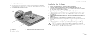
... Lift the keyboard off the computer. 3 2 1 1 keyboard 2 keyboard cable 3 keyboard backlight cable connector CHAPTER 8: KEYBOARD Replacing the Keyboard 1. Replace the three screws that no stray screws remain inside the computer. Failure to do so may result in "Before You Begin" on...035 /035 Turn the keyboard over. 10. Replace the center control cover (see "Replacing the Memory Module(s)" on page 31). 6. Replace the memory module(s) (see "Replacing the Center Control Cover" on page 23). 7. Replace the battery pack (see "Replacing the Battery Pack" on the chassis. 4. 9. Align the...
... Lift the keyboard off the computer. 3 2 1 1 keyboard 2 keyboard cable 3 keyboard backlight cable connector CHAPTER 8: KEYBOARD Replacing the Keyboard 1. Replace the three screws that no stray screws remain inside the computer. Failure to do so may result in "Before You Begin" on...035 /035 Turn the keyboard over. 10. Replace the center control cover (see "Replacing the Memory Module(s)" on page 31). 6. Replace the memory module(s) (see "Replacing the Center Control Cover" on page 23). 7. Replace the battery pack (see "Replacing the Battery Pack" on the chassis. 4. 9. Align the...
Service Manual
Page 39
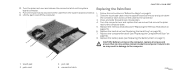
...2. Slide the touch pad cable into position. 4. Replace the memory module(s) (see "Replacing the Battery Pack" on page 11). 4 3 CAUTION: Before turning on page 23). 6. Replace the battery pack (see "Replacing the Memory Module(s)" on the computer, replace all screws and ensure that secure the palm rest ...the computer base. 5. CHAPTER 9: PALM REST 10. Turn the palm rest over and replace the two screws that no stray screws remain inside the computer. Replace the compartment door (see "Replacing the Hard Drive" on page 18). 7. Follow the instructions in damage to the ...
...2. Slide the touch pad cable into position. 4. Replace the memory module(s) (see "Replacing the Battery Pack" on page 11). 4 3 CAUTION: Before turning on page 23). 6. Replace the battery pack (see "Replacing the Memory Module(s)" on the computer, replace all screws and ensure that secure the palm rest ...the computer base. 5. CHAPTER 9: PALM REST 10. Turn the palm rest over and replace the two screws that no stray screws remain inside the computer. Replace the compartment door (see "Replacing the Hard Drive" on page 18). 7. Follow the instructions in damage to the ...
Service Manual
Page 43
..." on page 18). 8. Follow the instructions in damage to the bottom of the computer. 4. Replace the battery pack (see "Replacing the Center Control Cover" on page 14). 9. Turn the computer over and replace the four screws that secure the air vents to the computer. 1 air vents (2) 2 screws (2) 043 /043 Turn the computer over and...
..." on page 18). 8. Follow the instructions in damage to the bottom of the computer. 4. Replace the battery pack (see "Replacing the Center Control Cover" on page 14). 9. Turn the computer over and replace the four screws that secure the air vents to the computer. 1 air vents (2) 2 screws (2) 043 /043 Turn the computer over and...
Service Manual
Page 47
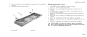
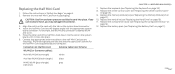
...Replace the memory module(s) (see "Replacing the Keyboard" on page 35). 8. Replacing the Half Mini-Card 1. Replace the keyboard (see "Replacing...21). 10. Replace the center control cover (see "Replacing the Compartment Door"... on page 31). 9. The following table provides the antenna cable color scheme for the half Mini-Card supported by your computer. If you use excessive force, you are installing. Align the notch on the card with the tab on . 5. Replace... the compartment door (see "Replacing the Center Control Cover...
...Replace the memory module(s) (see "Replacing the Keyboard" on page 35). 8. Replacing the Half Mini-Card 1. Replace the keyboard (see "Replacing...21). 10. Replace the center control cover (see "Replacing the Compartment Door"... on page 31). 9. The following table provides the antenna cable color scheme for the half Mini-Card supported by your computer. If you use excessive force, you are installing. Align the notch on the card with the tab on . 5. Replace... the compartment door (see "Replacing the Center Control Cover...

Service Manual
Page 49
... pressure to the computer. 12. If you use excessive force, you are installing a communication card from its packaging. Press the other than Dell or Alienware, you are installing. 7. Replace the battery pack (see "Replacing the Palm Rest" on the connector. 4. CAUTION: Before turning on . 5. For example, the WPAN card connector is labeled WPAN and so...
... pressure to the computer. 12. If you use excessive force, you are installing a communication card from its packaging. Press the other than Dell or Alienware, you are installing. 7. Replace the battery pack (see "Replacing the Palm Rest" on the connector. 4. CAUTION: Before turning on . 5. For example, the WPAN card connector is labeled WPAN and so...
Service Manual
Page 54
... in sequential order (indicated on page 11). Replace the battery pack (see "Replacing the Compartment Door" on page 43). 8. Do not reuse the old thermal cooling pads. 3. Replace the compartment door (see "Replacing the Battery Pack" on the processor fan and heat sink assembly). 5. Replace the right air-vent (see "Replacing the Center Control Cover" on page 18...
... in sequential order (indicated on page 11). Replace the battery pack (see "Replacing the Compartment Door" on page 43). 8. Do not reuse the old thermal cooling pads. 3. Replace the compartment door (see "Replacing the Battery Pack" on the processor fan and heat sink assembly). 5. Replace the right air-vent (see "Replacing the Center Control Cover" on page 18...
Service Manual
Page 56
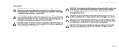
...computer. CHAPTER 13: PROCESSOR CAUTION: To prevent intermittent contact between the ZIF-socket cam screw and the processor when removing or replacing the processor, press to apply slight pressure to the processor when turning the cam screw. For additional safety best practices information, see... safety information that shipped with your computer. CAUTION: To avoid damage to the system board, remove the main battery (see the Regulatory Compliance Homepage at www.dell.com/regulatory_compliance. CAUTION: To help prevent damage to the processor, hold the screwdriver so that it is not ...
...computer. CHAPTER 13: PROCESSOR CAUTION: To prevent intermittent contact between the ZIF-socket cam screw and the processor when removing or replacing the processor, press to apply slight pressure to the processor when turning the cam screw. For additional safety best practices information, see... safety information that shipped with your computer. CAUTION: To avoid damage to the system board, remove the main battery (see the Regulatory Compliance Homepage at www.dell.com/regulatory_compliance. CAUTION: To help prevent damage to the processor, hold the screwdriver so that it is not ...


