Manual
Page 3
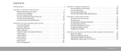
... GETTING TO KNOW YOUR LAPTOP 13 Front View Features 14 Left View Features 15 Right View Features 16 Display Features 17 Computer Base and Keyboard Features 18 Status Lights 19 Touch Controls 19 Power Button 20... 28 Connecting USB Devices 29 Connecting FireWire (IEEE 1394) Devices 29 CHAPTER 4: USING YOUR LAPTOP 31 Alienware Command Center 32 Stealth Mode 32 Using Removable Media and Cards 32 Using the Optical Drive 33 Using .... . 41 Before You Begin 42 Replacing the Battery Pack 44 Upgrading or Replacing Memory 45 Upgrading or Replacing the Hard Drive 47 CONTENTS 3
... GETTING TO KNOW YOUR LAPTOP 13 Front View Features 14 Left View Features 15 Right View Features 16 Display Features 17 Computer Base and Keyboard Features 18 Status Lights 19 Touch Controls 19 Power Button 20... 28 Connecting USB Devices 29 Connecting FireWire (IEEE 1394) Devices 29 CHAPTER 4: USING YOUR LAPTOP 31 Alienware Command Center 32 Stealth Mode 32 Using Removable Media and Cards 32 Using the Optical Drive 33 Using .... . 41 Before You Begin 42 Replacing the Battery Pack 44 Upgrading or Replacing Memory 45 Upgrading or Replacing the Hard Drive 47 CONTENTS 3
Manual
Page 16
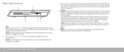
...storage devices (such as external hard drives or optical drives) or USB devices (such as a mouse, keyboard, printer, external drive, or MP3 player. 16 CHAPTER 2: GETTING TO KNOW YOUR LAPTOP Plays or records only standard-size (12 cm) CDs, DVDs, and Blu-ray Discs (optional). If you to... charge USB devices when the computer is designed only for additional memory, wired and wireless communications, multimedia, and security features. In such cases turn off your computer while charging a USB device, the device will stop ...
...storage devices (such as external hard drives or optical drives) or USB devices (such as a mouse, keyboard, printer, external drive, or MP3 player. 16 CHAPTER 2: GETTING TO KNOW YOUR LAPTOP Plays or records only standard-size (12 cm) CDs, DVDs, and Blu-ray Discs (optional). If you to... charge USB devices when the computer is designed only for additional memory, wired and wireless communications, multimedia, and security features. In such cases turn off your computer while charging a USB device, the device will stop ...
Comprehensive Specifications
Page 4
...and Back 377.93 mm (14.88 inches) 308.51 mm (12.15 inches) 4.08 kg (9.00 lb) NOTE: The weight of DDR3 memory up to 8 MB Bus clock 133 MHz System chipset Mobile Intel PM55 SDRAM bus width one or two 64-bit channels of your laptop will ... EPROM 16 Mbit Graphics bus PCIe x16 bus supporting x16 PCIe MXM 3.0 graphics cards PCI bus 32 bits Memory Connectors Capacities Memory types Memory configurations possible two internally-accessible SODIMM sockets 1 GB, 2 GB, and 4 GB modules 1067 MHz and 1333 MHz DDR3 2 GB, 3 GB, 4 GB, and 8 GB 04 /04 Computer Model Alienware M15x Dimensions ...
...and Back 377.93 mm (14.88 inches) 308.51 mm (12.15 inches) 4.08 kg (9.00 lb) NOTE: The weight of DDR3 memory up to 8 MB Bus clock 133 MHz System chipset Mobile Intel PM55 SDRAM bus width one or two 64-bit channels of your laptop will ... EPROM 16 Mbit Graphics bus PCIe x16 bus supporting x16 PCIe MXM 3.0 graphics cards PCI bus 32 bits Memory Connectors Capacities Memory types Memory configurations possible two internally-accessible SODIMM sockets 1 GB, 2 GB, and 4 GB modules 1067 MHz and 1333 MHz DDR3 2 GB, 3 GB, 4 GB, and 8 GB 04 /04 Computer Model Alienware M15x Dimensions ...
Service Manual
Page 69
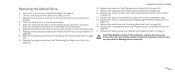
...). 4. Follow the instructions in "Before You Begin" on page 21). 6. Remove the graphics card from the system board connector. 1 2 1 screws (2) CHAPTER 16: GRAPHICS CARD 2 graphics card 069 /069 Remove the memory module(s) (see "Removing the Air Vents" on page 42). 8. Removing the Graphics Card 1. Remove the two screws that secure the graphics...
...). 4. Follow the instructions in "Before You Begin" on page 21). 6. Remove the graphics card from the system board connector. 1 2 1 screws (2) CHAPTER 16: GRAPHICS CARD 2 graphics card 069 /069 Remove the memory module(s) (see "Removing the Air Vents" on page 42). 8. Removing the Graphics Card 1. Remove the two screws that secure the graphics...
Service Manual
Page 70
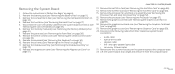
... CAUTION: Before turning on page 43). 7. Follow the instructions in damage to the system board. 4. Replace the left air-vent (see "Replacing the Memory Module(s)" on page 18). 10. Replace the graphics card fan (see "Replacing the Hard Drive" on page 23). 9. Replace the hard drive (see ... screws remain inside the computer. Replace the compartment door (see "Replacing the Graphics Card Heat Sink" on page 31). 8. CHAPTER 16: GRAPHICS CARD 070 /070 Replace the graphics card heat sink (see "Replacing the Compartment Door" on page 6. 2. Replacing the Graphics Card 1.
... CAUTION: Before turning on page 43). 7. Follow the instructions in damage to the system board. 4. Replace the left air-vent (see "Replacing the Memory Module(s)" on page 18). 10. Replace the graphics card fan (see "Replacing the Hard Drive" on page 23). 9. Replace the hard drive (see ... screws remain inside the computer. Replace the compartment door (see "Replacing the Graphics Card Heat Sink" on page 31). 8. CHAPTER 16: GRAPHICS CARD 070 /070 Replace the graphics card heat sink (see "Replacing the Compartment Door" on page 6. 2. Replacing the Graphics Card 1.
Service Manual
Page 99
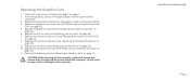
...(see "Replacing the Hard Drive" on page 31). 13. Replace the hard drive (see "Replacing the Center Control Cover" on page 18). 16. Replace the three screws that secure the optical drive to do so may result in the computer base. 5. Replace the keyboard (see "Replacing the... Memory Module(s)" on page 35). 12. Replace the memory module(s) (see "Replacing the Keyboard" on page 23). 15. Follow the instructions in "Before You Begin" on the computer,...
...(see "Replacing the Hard Drive" on page 31). 13. Replace the hard drive (see "Replacing the Center Control Cover" on page 18). 16. Replace the three screws that secure the optical drive to do so may result in the computer base. 5. Replace the keyboard (see "Replacing the... Memory Module(s)" on page 35). 12. Replace the memory module(s) (see "Replacing the Keyboard" on page 23). 15. Follow the instructions in "Before You Begin" on the computer,...
Service Manual
Page 102
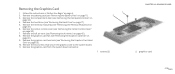
...and remove it from their respective system board connectors: • audio cable • optical-drive cable • speaker cable • left- Remove the memory module(s) (see "Removing the Palm Rest" on page 30). 9. Remove the five screws that secure the system board to the computer base. 22. Remove...Card (see "Removing the Hard Drive" on page 34). 10. Remove the hard drive (see "Removing the Half Mini-Card" on page 52). 16. CHAPTER 22: SYSTEM BOARD 13. Removing the System Board 1. Remove the magnesium cover (see "Removing the Processor Fan and Heat Sink Assembly" on ...
...and remove it from their respective system board connectors: • audio cable • optical-drive cable • speaker cable • left- Remove the memory module(s) (see "Removing the Palm Rest" on page 30). 9. Remove the five screws that secure the system board to the computer base. 22. Remove...Card (see "Removing the Hard Drive" on page 34). 10. Remove the hard drive (see "Removing the Half Mini-Card" on page 52). 16. CHAPTER 22: SYSTEM BOARD 13. Removing the System Board 1. Remove the magnesium cover (see "Removing the Processor Fan and Heat Sink Assembly" on ...
Service Manual
Page 104
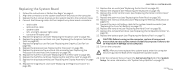
...Palm Rest" on page 85). Replace the palm rest (see "Replacing the Magnesium Cover" on page 39). 18. Replace the memory module(s) (see "Replacing the Air Vents" on page 6. 2. Failure to do so may result in "Before You Begin".... Replace the five screws that no stray screws remain inside the computer. Replace the air vents (see "Replacing the Memory Module(s)" on page 14). 22. Replace the center control cover (see "Replacing the Compartment Door" on page 23).... 75). 13. Replace the keyboard (see "Replacing the Display Assembly" on page 35). 16. Turn on the computer. 3.
...Palm Rest" on page 85). Replace the palm rest (see "Replacing the Magnesium Cover" on page 39). 18. Replace the memory module(s) (see "Replacing the Air Vents" on page 6. 2. Failure to do so may result in "Before You Begin".... Replace the five screws that no stray screws remain inside the computer. Replace the air vents (see "Replacing the Memory Module(s)" on page 14). 22. Replace the center control cover (see "Replacing the Compartment Door" on page 23).... 75). 13. Replace the keyboard (see "Replacing the Display Assembly" on page 35). 16. Turn on the computer. 3.


