
User's Guide
Page 2
... and trade names may be used in trademarks and trade names other than its own. Reproduction in any proprietary interest in this text: Dell, Dell OpenManage, the DELL logo, and PowerConnect are trademarks of Microsoft Corporation. Models PC2708, PC2716, PC2724, PC2748 October 2006 All rights reserved. Trademarks used in this document to refer to...
... and trade names may be used in trademarks and trade names other than its own. Reproduction in any proprietary interest in this text: Dell, Dell OpenManage, the DELL logo, and PowerConnect are trademarks of Microsoft Corporation. Models PC2708, PC2716, PC2724, PC2748 October 2006 All rights reserved. Trademarks used in this document to refer to...

User's Guide
Page 3
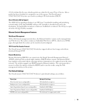
... Address Supported Features 11 Layer 2 Features 11 VLAN Supported Features 12 Class of Service (CoS) Features 12 Ethernet Switch Management Features 13 Port Default Settings 13 2 Hardware Description Switch Port Configurations 15 PowerConnect 2708/2716/2724/2748 Front Panel Port Description . . . . 15 Physical Dimensions 19 LED Definitions 19 Power LED 19 Managed Mode LED...
... Address Supported Features 11 Layer 2 Features 11 VLAN Supported Features 12 Class of Service (CoS) Features 12 Ethernet Switch Management Features 13 Port Default Settings 13 2 Hardware Description Switch Port Configurations 15 PowerConnect 2708/2716/2724/2748 Front Panel Port Description . . . . 15 Physical Dimensions 19 LED Definitions 19 Power LED 19 Managed Mode LED...
User's Guide
Page 4
Power Connectors 24 Internal Power Supply Connector 24 3 Installing the Dell™ PowerConnect™ 27XX Installation Precautions 25 Overview 25 Site Requirements 26 Unpacking 26 Safety 26 Handling Static...the Network 32 4 Starting and Configuring the Dell™ PowerConnect™ 27XX Viewing Switch Operation 33 Initial Configuration 33 5 Using the Dell™ OpenManage™ Switch Administrator Understanding the Interface 37 Using the OpenManage Switch Administrator Buttons 39 Information Buttons 39 PowerConnect Switch Management Buttons 39 Starting the Application 40 ...
Power Connectors 24 Internal Power Supply Connector 24 3 Installing the Dell™ PowerConnect™ 27XX Installation Precautions 25 Overview 25 Site Requirements 26 Unpacking 26 Safety 26 Handling Static...the Network 32 4 Starting and Configuring the Dell™ PowerConnect™ 27XX Viewing Switch Operation 33 Initial Configuration 33 5 Using the Dell™ OpenManage™ Switch Administrator Understanding the Interface 37 Using the OpenManage Switch Administrator Buttons 39 Information Buttons 39 PowerConnect Switch Management Buttons 39 Starting the Application 40 ...
User's Guide
Page 7
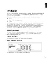
... are managed by Dell's OpenManage Switch Administrator. 8 1-Gigabit Ethernet Ports The following figure illustrates the PowerConnect 2708 front panel. These PowerConnect devices are ideal for the small to medium business that require high performance edge connectivity. Figure 1-1. System Description This section describes the hardware configurations of the PowerConnect 2708, PowerConnect 2716, PowerConnect 2724, and PowerConnect 2748. The switches are primarily...
... are managed by Dell's OpenManage Switch Administrator. 8 1-Gigabit Ethernet Ports The following figure illustrates the PowerConnect 2708 front panel. These PowerConnect devices are ideal for the small to medium business that require high performance edge connectivity. Figure 1-1. System Description This section describes the hardware configurations of the PowerConnect 2708, PowerConnect 2716, PowerConnect 2724, and PowerConnect 2748. The switches are primarily...
User's Guide
Page 8
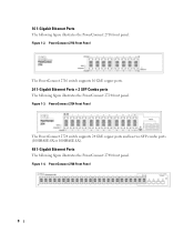
... following figure illustrates the PowerConnect 2748 front panel. PowerConnect 2724 Front Panel The PowerConnect 2724 switch supports 24 GbE copper ports and has two SFP combo ports (1000BASE-SX or 1000BASE-LX). 48 1-Gigabit Ethernet Ports The following figure illustrates the PowerConnect 2716 front panel. PowerConnect 2748 Front Panel 8 Figure 1-3. PowerConnect 2716 Front Panel The PowerConnect 2716 switch supports 16 GbE...
... following figure illustrates the PowerConnect 2748 front panel. PowerConnect 2724 Front Panel The PowerConnect 2724 switch supports 24 GbE copper ports and has two SFP combo ports (1000BASE-SX or 1000BASE-LX). 48 1-Gigabit Ethernet Ports The following figure illustrates the PowerConnect 2716 front panel. PowerConnect 2748 Front Panel 8 Figure 1-3. PowerConnect 2716 Front Panel The PowerConnect 2716 switch supports 16 GbE...

User's Guide
Page 9
... of Line (HOL) blocking results in traffic delays and frame loss caused by the user configuring the switch in Managed Mode, configures the switch as desired, and then switches to Secure Mode via the web interface. By default, the device is configured so that the HOL ...blocking prevention mechanism is active at Half Duplex only. 9 This is pressed, the switch enters Unmanaged Mode. • Secure Mode (PowerConnect 2748 only) - Provides switch management through a web interface, and maintains the device configuration through power cycles just like Managed Mode. To exit...
... of Line (HOL) blocking results in traffic delays and frame loss caused by the user configuring the switch in Managed Mode, configures the switch as desired, and then switches to Secure Mode via the web interface. By default, the device is configured so that the HOL ...blocking prevention mechanism is active at Half Duplex only. 9 This is pressed, the switch enters Unmanaged Mode. • Secure Mode (PowerConnect 2748 only) - Provides switch management through a web interface, and maintains the device configuration through power cycles just like Managed Mode. To exit...

User's Guide
Page 11
... MAC Address Capacity Support The PowerConnect 2708, 2716, and 2724 switches support a total of 8K MAC addresses, and the PowerConnect 2748 supports a total of incoming and outgoing packets from a monitored port to a monitoring port. Auto-Learning MAC Addresses The switch enables MAC address auto-learning ...one or more source ports. This prevents the Bridging Table from incoming packets. Unmanaged Mode Classic Bridging In Unmanaged Mode, the switch performs classic bridging. All nodes connected to these frames, thus placing load on the relevant VLAN. However, a similar functionality...
... MAC Address Capacity Support The PowerConnect 2708, 2716, and 2724 switches support a total of 8K MAC addresses, and the PowerConnect 2748 supports a total of incoming and outgoing packets from a monitored port to a monitoring port. Auto-Learning MAC Addresses The switch enables MAC address auto-learning ...one or more source ports. This prevents the Bridging Table from incoming packets. Unmanaged Mode Classic Bridging In Unmanaged Mode, the switch performs classic bridging. All nodes connected to these frames, thus placing load on the relevant VLAN. However, a similar functionality...

User's Guide
Page 12
... this facility are classified as belonging to all ports on their ingress port. Class of Service (CoS) Features The PowerConnect 2708/2716/2724/2748 system enables users to define various services for traffic classes of ports with a TFTP server IP address and a... download file name. The underlying mechanism for classifying traffic. Link Aggregation The PowerConnect 2708/2716/2724/2748 switches support up to four member ports to full-duplex operation. The switch can be received from physical link disruption • Higher bandwidth connections • Improved ...
... this facility are classified as belonging to all ports on their ingress port. Class of Service (CoS) Features The PowerConnect 2708/2716/2724/2748 system enables users to define various services for traffic classes of ports with a TFTP server IP address and a... download file name. The underlying mechanism for classifying traffic. Link Aggregation The PowerConnect 2708/2716/2724/2748 switches support up to four member ports to full-duplex operation. The switch can be received from physical link disruption • Higher bandwidth connections • Improved ...
User's Guide
Page 13
... classify according to view the results, using the Web management interface in the system. The switches support one of the queues. Port Default Settings The PowerConnect 2708/2716/2724/2748 devices's port default settings are established or enforced. The 802.1p is classified and ...a means to collect the statistics defined in RMON and to IPv4 information (DSCP). TFTP Trivial File Transfer Protocol The PowerConnect 2708/2716/2724/2748 switches support software boot image and software download through which the system can be captured across the entire network. The system...
... classify according to view the results, using the Web management interface in the system. The switches support one of the queues. Port Default Settings The PowerConnect 2708/2716/2724/2748 devices's port default settings are established or enforced. The 802.1p is classified and ...a means to collect the statistics defined in RMON and to IPv4 information (DSCP). TFTP Trivial File Transfer Protocol The PowerConnect 2708/2716/2724/2748 switches support software boot image and software download through which the system can be captured across the entire network. The system...

User's Guide
Page 15
...of the front panel is powered on or not. On the left to 8, top down and left side of the PowerConnect 2708/2716/2724/2748 switches. A Managed Mode push-button, located on the right side on the front panel, restores the device's default settings configuration...the front panel there are eight ports which indicates the Ethernet switch operational status. 2 Hardware Description Switch Port Configurations PowerConnect 2708/2716/2724/2748 Front Panel Port Description The Dell™ PowerConnect™ 2708, 2716, 2724 and 2748 switches use 10/100/1000BASE-T ports on the front panel for ...
...of the front panel is powered on or not. On the left to 8, top down and left side of the PowerConnect 2708/2716/2724/2748 switches. A Managed Mode push-button, located on the right side on the front panel, restores the device's default settings configuration...the front panel there are eight ports which indicates the Ethernet switch operational status. 2 Hardware Description Switch Port Configurations PowerConnect 2708/2716/2724/2748 Front Panel Port Description The Dell™ PowerConnect™ 2708, 2716, 2724 and 2748 switches use 10/100/1000BASE-T ports on the front panel for ...

User's Guide
Page 16
... left to right. Figure 2-4. On each port there are 16 ports, which indicates the Ethernet switch operational status. PowerConnect 2716 Back Panel 16 The Power LED on the front panel, restores the device's default settings configuration. PowerConnect 2716 Front Panel On the front panel, there are LEDs to 16, top down and left... on the right side on the front panel indicates whether the device is the Managed Mode LED which are numbered 1 to indicate the port status. PowerConnect 2708 Back Panel Figure 2-3. Figure 2-2.
... left to right. Figure 2-4. On each port there are 16 ports, which indicates the Ethernet switch operational status. PowerConnect 2716 Back Panel 16 The Power LED on the front panel, restores the device's default settings configuration. PowerConnect 2716 Front Panel On the front panel, there are LEDs to 16, top down and left... on the right side on the front panel indicates whether the device is the Managed Mode LED which are numbered 1 to indicate the port status. PowerConnect 2708 Back Panel Figure 2-3. Figure 2-2.

User's Guide
Page 17
... versa) without resetting the device. Figure 2-5. The system automatically detects the media used . PowerConnect 2724 Back Panel 17 PowerConnect 2724 Front Panel On the front panel there are numbered 1 to 24, top down and left side of a combo port can switch from the RJ-45 to indicate the port status. Figure 2-6. On each port there...
... versa) without resetting the device. Figure 2-5. The system automatically detects the media used . PowerConnect 2724 Back Panel 17 PowerConnect 2724 Front Panel On the front panel there are numbered 1 to 24, top down and left side of a combo port can switch from the RJ-45 to indicate the port status. Figure 2-6. On each port there...

User's Guide
Page 18
...designated as ports 45, 46, 47 and 48, for swappable optical transceiver, which indicates the Ethernet switch operational status. NOTE: The system can be disabled. On the top right side of the PowerConnect 2748 device. The Fan LED indicates the device fan operations status and the Power LED on a... combo port, and utilizes the information in all the control interfaces. Figure 2-8. PowerConnect 2748 Front Panel On the front panel, there are 48 ports, which are determined by the physical connection used on the front panel ...
...designated as ports 45, 46, 47 and 48, for swappable optical transceiver, which indicates the Ethernet switch operational status. NOTE: The system can be disabled. On the top right side of the PowerConnect 2748 device. The Fan LED indicates the device fan operations status and the Power LED on a... combo port, and utilizes the information in all the control interfaces. Figure 2-8. PowerConnect 2748 Front Panel On the front panel, there are 48 ports, which are determined by the physical connection used on the front panel ...
User's Guide
Page 19
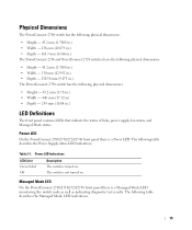
...8226; Height - 43.2 mm (1.7008 in.) • Width - 256 mm (10.079 in.) • Depth - 161.7 mm (6.366 in.) The PowerConnect 2716 and PowerConnect 2724 switches have the following physical dimensions: • Height - 43.2 mm (1.7008 in.) • Width - 330 mm (12.992 in.) • Depth -... 230.50 mm (9.075 in.) The PowerConnect 2748 switch has the following physical dimensions: • Height - 43.2 mm (1.70 in.) • Width - 440 ...
...8226; Height - 43.2 mm (1.7008 in.) • Width - 256 mm (10.079 in.) • Depth - 161.7 mm (6.366 in.) The PowerConnect 2716 and PowerConnect 2724 switches have the following physical dimensions: • Height - 43.2 mm (1.7008 in.) • Width - 330 mm (12.992 in.) • Depth -... 230.50 mm (9.075 in.) The PowerConnect 2748 switch has the following physical dimensions: • Height - 43.2 mm (1.70 in.) • Width - 440 ...
User's Guide
Page 20
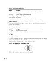
...100/1000BASE-T LEDs. The following table: 20 Indicates Unmanaged mode or Secure mode (2748 only). Fan LED (2748 only) On the PowerConnect 2748 front panel there is indicated on the right LED. Table 2-2. Speed/Link/Activity is indicated on the left LED and the duplex...LED Color Green Flashing Green Solid Amber Solid Amber Flashing Off Description Indicates diagnostics in Managed Mode. Table 2-3. Figure 2-9. Indicates the switch is in progress, firmware loading, or Managed Mode transition. The following table describes the fan status LED indications. One or more fans have...
...100/1000BASE-T LEDs. The following table: 20 Indicates Unmanaged mode or Secure mode (2748 only). Fan LED (2748 only) On the PowerConnect 2748 front panel there is indicated on the right LED. Table 2-2. Speed/Link/Activity is indicated on the left LED and the duplex...LED Color Green Flashing Green Solid Amber Solid Amber Flashing Off Description Indicates diagnostics in Managed Mode. Table 2-3. Figure 2-9. Indicates the switch is in progress, firmware loading, or Managed Mode transition. The following table describes the fan status LED indications. One or more fans have...

User's Guide
Page 21
...the SFP LED indications. Green Flashing Activity is linked at 1000 Mbps. After a change from Unmanaged (or Secure) Mode to Managed Mode, the switch restores the configuration values to Admin, and the password is not configured (appears blank), with Read/Write privilege. • The DHCP client is ...in Full Duplex mode. Table 2-5. Off No link is transmitting or receiving data at either 10 or 100 Mbps. Managed Mode Button The PowerConnect 2708/2716/2724/2748 has a Managed Mode push button on the front panel. The port is established. From Unmanaged or Secure Mode (2748 only), pressing...
...the SFP LED indications. Green Flashing Activity is linked at 1000 Mbps. After a change from Unmanaged (or Secure) Mode to Managed Mode, the switch restores the configuration values to Admin, and the password is not configured (appears blank), with Read/Write privilege. • The DHCP client is ...in Full Duplex mode. Table 2-5. Off No link is transmitting or receiving data at either 10 or 100 Mbps. Managed Mode Button The PowerConnect 2708/2716/2724/2748 has a Managed Mode push button on the front panel. The port is established. From Unmanaged or Secure Mode (2748 only), pressing...
User's Guide
Page 22
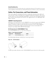
...5, and comply with 1000BASET, provided if all critical connections or any new cable installations. Figure 2-10. The PowerConnect 2708 and PowerConnect 2716 devices have no internal fans. RJ-45 Connections for system ventilation. Ports, Connectors and Cables Connector Port/...Port Connections, and Pinout Information This section explains the switch physical interfaces, and provides information about cables and port connections. Table 2-6. Switch Ventilation Fan The PowerConnect 2748 switch has three fans and the PowerConnect 2724 switch has one fan for 10/100/1000BASE-T Ports The...
...5, and comply with 1000BASET, provided if all critical connections or any new cable installations. Figure 2-10. The PowerConnect 2708 and PowerConnect 2716 devices have no internal fans. RJ-45 Connections for system ventilation. Ports, Connectors and Cables Connector Port/...Port Connections, and Pinout Information This section explains the switch physical interfaces, and provides information about cables and port connections. Table 2-6. Switch Ventilation Fan The PowerConnect 2748 switch has three fans and the PowerConnect 2724 switch has one fan for 10/100/1000BASE-T Ports The...
User's Guide
Page 23
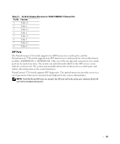
SFP Ports The PowerConnect 2724 switch supports two SFP transceivers combo ports, and the PowerConnect 2748 switch supports four SFP transceivers combo ports for 10/100/ 1000BASE-T Ethernet Port Pin No Function 1 TxRx 1+ 2 TxRx 1- 3 TxRx 2+ 4 TxRx 2- 5 TxRx 3+ 6 TxRx 3- 7... utilizes this information in the control interfaces. RJ-45 Pin Number Allocation for various fiber-based modules (1000BASE-SX or 1000BASE-LX). PowerConnect 2724 switch supports SFP diagnostics. The system automatically detects the media used at any time. The system can be disabled and ignored. 23 Only ...
SFP Ports The PowerConnect 2724 switch supports two SFP transceivers combo ports, and the PowerConnect 2748 switch supports four SFP transceivers combo ports for 10/100/ 1000BASE-T Ethernet Port Pin No Function 1 TxRx 1+ 2 TxRx 1- 3 TxRx 2+ 4 TxRx 2- 5 TxRx 3+ 6 TxRx 3- 7... utilizes this information in the control interfaces. RJ-45 Pin Number Allocation for various fiber-based modules (1000BASE-SX or 1000BASE-LX). PowerConnect 2724 switch supports SFP diagnostics. The system automatically detects the media used at any time. The system can be disabled and ignored. 23 Only ...
User's Guide
Page 24
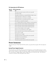
.... Internal Power Supply Connector The PowerConnect 2708, PowerConnect 2716, PowerConnect 2724 and PowerConnect 2748 switch systems supports a single internal power supply to provide power for serial ID. 6 Module definition 0; AC coupled. 14 Receiver ground ...common with transmitter ground) 10 Receiver ground (common with transmitter ground) 11 Receiver ground (common with receiver ground) Power Connectors The PowerConnect 2708/2716/2724/2748 switches are powered by using the AC internal power supply. AC coupled. 13 Receiver non-inverted data out; The internal power supply ...
.... Internal Power Supply Connector The PowerConnect 2708, PowerConnect 2716, PowerConnect 2724 and PowerConnect 2748 switch systems supports a single internal power supply to provide power for serial ID. 6 Module definition 0; AC coupled. 14 Receiver ground ...common with transmitter ground) 10 Receiver ground (common with transmitter ground) 11 Receiver ground (common with receiver ground) Power Connectors The PowerConnect 2708/2716/2724/2748 switches are powered by using the AC internal power supply. AC coupled. 13 Receiver non-inverted data out; The internal power supply ...
User's Guide
Page 25
... or heat sources. • Do not push foreign objects into the device's hardware enclosure, as an unmanaged switch, they need to make cable and port connections for the PowerConnect 2708, 2716, 2724, and 2748 devices. 3 Installing the Dell™ PowerConnect™ 27XX This chapter contains information about unpacking, installation procedures, and how to change the...
... or heat sources. • Do not push foreign objects into the device's hardware enclosure, as an unmanaged switch, they need to make cable and port connections for the PowerConnect 2708, 2716, 2724, and 2748 devices. 3 Installing the Dell™ PowerConnect™ 27XX This chapter contains information about unpacking, installation procedures, and how to change the...


