
User's Guide
Page 3
...Gigabit Ethernet Ports 8 24 1-Gigabit Ethernet Ports + 2 SFP Combo ports 8 48 1-Gigabit Ethernet Ports 8 Features 9 General Features 9 MAC Address Supported Features 11 Layer 2 Features 11 VLAN Supported Features 12 Class of Service (CoS) Features 12 Ethernet Switch Management Features 13 Port Default Settings 13 2 Hardware Description Switch Port Configurations 15 PowerConnect 2708/2716/2724/2748 Front Panel Port Description . . . . 15 Physical Dimensions 19 LED Definitions 19 Power LED 19 Managed Mode LED 19 Fan LED (2748 only 20 Port LEDs 20 Managed Mode Button 21 Switch...
...Gigabit Ethernet Ports 8 24 1-Gigabit Ethernet Ports + 2 SFP Combo ports 8 48 1-Gigabit Ethernet Ports 8 Features 9 General Features 9 MAC Address Supported Features 11 Layer 2 Features 11 VLAN Supported Features 12 Class of Service (CoS) Features 12 Ethernet Switch Management Features 13 Port Default Settings 13 2 Hardware Description Switch Port Configurations 15 PowerConnect 2708/2716/2724/2748 Front Panel Port Description . . . . 15 Physical Dimensions 19 LED Definitions 19 Power LED 19 Managed Mode LED 19 Fan LED (2748 only 20 Port LEDs 20 Managed Mode Button 21 Switch...
User's Guide
Page 7
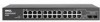
... used to connect workstations and other network devices, such as: • Servers • Hubs (Wireless LAN Access Points) • Routers The PowerConnect devices are primarily for the Small Office/Home Office (SOHO) that requires high performance network connectivity along with advanced web management features.The PowerConnect management features are designed to medium business that require high performance edge connectivity. These PowerConnect devices are managed by Dell's OpenManage Switch Administrator. 8 1-Gigabit Ethernet Ports...
... used to connect workstations and other network devices, such as: • Servers • Hubs (Wireless LAN Access Points) • Routers The PowerConnect devices are primarily for the Small Office/Home Office (SOHO) that requires high performance network connectivity along with advanced web management features.The PowerConnect management features are designed to medium business that require high performance edge connectivity. These PowerConnect devices are managed by Dell's OpenManage Switch Administrator. 8 1-Gigabit Ethernet Ports...

User's Guide
Page 9
... address of 192.168.2.1. • Managed Mode - By default, the device is configured so that the HOL blocking prevention mechanism is active at all ports is set to OFF. From Managed Mode, when the Managed Mode button is unavailable for the same egress port resources. Secure Mode works by the user configuring the switch in traffic delays and frame loss caused by traffic competing for additional incoming traffic. Back Pressure Support On half-duplex links...
... address of 192.168.2.1. • Managed Mode - By default, the device is configured so that the HOL blocking prevention mechanism is active at all ports is set to OFF. From Managed Mode, when the Managed Mode button is unavailable for the same egress port resources. Secure Mode works by the user configuring the switch in traffic delays and frame loss caused by traffic competing for additional incoming traffic. Back Pressure Support On half-duplex links...

User's Guide
Page 11
... ports. Users can specify which no traffic is not performed (where frames are aged out. Storm Control Storm Control enables limiting the amount of time are forwarded based only on their destination MAC address only, regardless of all ports on the relevant VLAN. MAC Address Supported Features MAC Address Capacity Support The PowerConnect 2708, 2716, and 2724 switches support a total of 8K MAC addresses, and the PowerConnect 2748 supports a total of incoming and outgoing packets from overflowing. Managed and Secure Modes VLAN-aware MAC...
... ports. Users can specify which no traffic is not performed (where frames are aged out. Storm Control Storm Control enables limiting the amount of time are forwarded based only on their destination MAC address only, regardless of all ports on the relevant VLAN. MAC Address Supported Features MAC Address Capacity Support The PowerConnect 2708, 2716, and 2724 switches support a total of 8K MAC addresses, and the PowerConnect 2748 supports a total of incoming and outgoing packets from overflowing. Managed and Secure Modes VLAN-aware MAC...

User's Guide
Page 12
... ports with a TFTP server IP address and a download file name. Packets sharing common attributes can then configure these values to the TFTP client and try to define various services for classifying traffic. The switch can be received from physical link disruption • Higher bandwidth connections • Improved bandwidth granularity • High bandwidth server connectivity A LAG is then used to VLANs based on the use of multiple priority queues for traffic classes of switching ports...
... ports with a TFTP server IP address and a download file name. Packets sharing common attributes can then configure these values to the TFTP client and try to define various services for classifying traffic. The switch can be received from physical link disruption • Higher bandwidth connections • Improved bandwidth granularity • High bandwidth server connectivity A LAG is then used to VLANs based on the use of multiple priority queues for traffic classes of switching ports...
User's Guide
Page 13
... are as follows: Function Flow Control (user-configurable) Backpressure (user-configurable) Auto Negotiation Speed (user-configurable) Auto Negotiation Duplex (user-configurable) MDIX (not user-configurable) Default Setting Off (disabled on ingress) Off (disabled on ingress) Enabled (1000 Mbps) Enabled (Full Duplex) On (relevant to view the results, using the Web management interface in RMON and to copper ports only) 13 The switches support one of the queues. Port Default Settings The PowerConnect 2708/2716/2724/2748 devices's port default settings are established or enforced...
... are as follows: Function Flow Control (user-configurable) Backpressure (user-configurable) Auto Negotiation Speed (user-configurable) Auto Negotiation Duplex (user-configurable) MDIX (not user-configurable) Default Setting Off (disabled on ingress) Off (disabled on ingress) Enabled (1000 Mbps) Enabled (Full Duplex) On (relevant to view the results, using the Web management interface in RMON and to copper ports only) 13 The switches support one of the queues. Port Default Settings The PowerConnect 2708/2716/2724/2748 devices's port default settings are established or enforced...

User's Guide
Page 15
... LEDs (Light Emitting Diode) to a network. The Power LED on the front panel indicates whether the device is the Managed Mode LED which are eight ports which indicates the Ethernet switch operational status. A Managed Mode push-button, located on the right side on or not. The combo 1000 Mbps optical ports can operate at 1000 Mbps, full-duplex mode. 2 Hardware Description Switch Port Configurations PowerConnect 2708/2716/2724/2748 Front Panel Port Description The Dell™ PowerConnect...
... LEDs (Light Emitting Diode) to a network. The Power LED on the front panel indicates whether the device is the Managed Mode LED which are eight ports which indicates the Ethernet switch operational status. A Managed Mode push-button, located on the right side on or not. The combo 1000 Mbps optical ports can operate at 1000 Mbps, full-duplex mode. 2 Hardware Description Switch Port Configurations PowerConnect 2708/2716/2724/2748 Front Panel Port Description The Dell™ PowerConnect...

User's Guide
Page 17
... in all the control interfaces. On each port there are two SFP (Small Form-Factor Plugable) ports, designated as ports 23 and 24, for swappable optical transceiver, which indicates the Ethernet switch operational status. On the left to the SFP (or vice versa) without resetting the device. The Power LED on the front panel, restores the device's default settings configuration. PowerConnect 2724 Back Panel 17 A Managed Mode push-button, located on the...
... in all the control interfaces. On each port there are two SFP (Small Form-Factor Plugable) ports, designated as ports 23 and 24, for swappable optical transceiver, which indicates the Ethernet switch operational status. On the left to the SFP (or vice versa) without resetting the device. The Power LED on the front panel, restores the device's default settings configuration. PowerConnect 2724 Back Panel 17 A Managed Mode push-button, located on the...

User's Guide
Page 21
...; The DHCP client is set off. • The device is linked at 1000 Mbps. Green Flashing Activity is for changing between Managed Mode and Unmanaged (or Secure) Mode. Table 2-4. The port is rebooted. 21 The port is set as the switch IP address. • Subnet mask changes to 255.255.255.0 • Graphical User Interface (GUI) login user name changes to factory default settings. Table 2-5. The Managed Mode button is occurring. Managed Mode Button The PowerConnect 2708/2716/2724/2748 has a Managed Mode push button on the...
...; The DHCP client is set off. • The device is linked at 1000 Mbps. Green Flashing Activity is for changing between Managed Mode and Unmanaged (or Secure) Mode. Table 2-4. The port is rebooted. 21 The port is set as the switch IP address. • Subnet mask changes to 255.255.255.0 • Graphical User Interface (GUI) login user name changes to factory default settings. Table 2-5. The Managed Mode button is occurring. Managed Mode Button The PowerConnect 2708/2716/2724/2748 has a Managed Mode push button on the...
User's Guide
Page 25
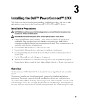
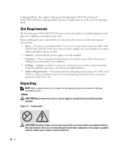
... Ethernet device to use the switch as explained in the Product Information Guide. The process of installing the PowerConnect switch consists of physically installing these devices and configuring them. The process consists of both hardware and software instructions. If the user wishes to cool before performing the procedures in this section: • Observe and follow the safety instructions located in the system documentation. Overview The PowerConnect...
... Ethernet device to use the switch as explained in the Product Information Guide. The process of installing the PowerConnect switch consists of physically installing these devices and configuring them. The process consists of both hardware and software instructions. If the user wishes to cool before performing the procedures in this section: • Observe and follow the safety instructions located in the system documentation. Overview The PowerConnect...
User's Guide
Page 26
... these parts, contact a service technician. 26 Allow clearance for operator access. Unpacking NOTE: Before unpacking the device, inspect the packaging and report any component that the site selected for Managed Mode Operation" explains how to set the switch to 95%, non-condensing. to Dell. Cabling is installed within 1.5 m (5 feet) of electrical noise such as radio transmitters, broadcast amplifiers, power lines, and fluorescent lighting...
... these parts, contact a service technician. 26 Allow clearance for operator access. Unpacking NOTE: Before unpacking the device, inspect the packaging and report any component that the site selected for Managed Mode Operation" explains how to set the switch to 95%, non-condensing. to Dell. Cabling is installed within 1.5 m (5 feet) of electrical noise such as radio transmitters, broadcast amplifiers, power lines, and fluorescent lighting...

User's Guide
Page 33
... PowerConnect device booted successfully. 33 Viewing Switch Operation The power-on self-test (POST) runs every time the switch is in the same state as an unmanaged switch, they can be downloaded from the Dell Support Website at support.dell.com. The boot process runs approximately 10 seconds. When a critical problem is necessary. No configuration is detected, the POST process fails and the Managed Mode LED indicator turns solid amber (PowerConnect 2748). If a critical problem...
... PowerConnect device booted successfully. 33 Viewing Switch Operation The power-on self-test (POST) runs every time the switch is in the same state as an unmanaged switch, they can be downloaded from the Dell Support Website at support.dell.com. The boot process runs approximately 10 seconds. When a critical problem is necessary. No configuration is detected, the POST process fails and the Managed Mode LED indicator turns solid amber (PowerConnect 2748). If a critical problem...
User's Guide
Page 34
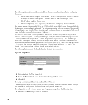
... VLAN 1 interface through which the device is to be managed (by default, every port is a member of the device (after the device is initially connected with the default settings), it can be monitored and configured. To change User name and Password, see Local User Database. The default IP address is 192.168.2.1, the default User Name is 'admin', and the default password is left blank. Login Screen 1 Enter admin in Unmanaged Mode (Managed Mode LED has stopped blinking...
... VLAN 1 interface through which the device is to be managed (by default, every port is a member of the device (after the device is initially connected with the default settings), it can be monitored and configured. To change User name and Password, see Local User Database. The default IP address is 192.168.2.1, the default User Name is 'admin', and the default password is left blank. Login Screen 1 Enter admin in Unmanaged Mode (Managed Mode LED has stopped blinking...
User's Guide
Page 39
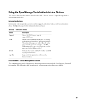
... Support Help About Log Out Description Opens the Dell Support page at support.dell.com. PowerConnect Switch Management Buttons The PowerConnect Switch Management buttons provide an easy method of the application and closes the browser window. Using the OpenManage Switch Administrator Buttons This section describes the buttons found on -line support and online help, as well as information about the OpenManage Switch Administrator interfaces. Contains the version and build number and Dell copyright information. Table 5-2. Information Buttons Information buttons provide access...
... Support Help About Log Out Description Opens the Dell Support page at support.dell.com. PowerConnect Switch Management Buttons The PowerConnect Switch Management buttons provide an easy method of the application and closes the browser window. Using the OpenManage Switch Administrator Buttons This section describes the buttons found on -line support and online help, as well as information about the OpenManage Switch Administrator interfaces. Contains the version and build number and Dell copyright information. Table 5-2. Information Buttons Information buttons provide access...
User's Guide
Page 40
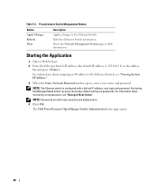
... a lost password, see "Viewing System IP Address." 3 When the Enter Network Password window opens, enter a user name and password. For information about assigning an IP address to the Ethernet Switch. NOTE: The Ethernet switch is : 192.168.2.1) in the address bar and press . Activating the Managed Mode button recovers the factory default setting (no password). Starting the Application 1 Open a Web browser. 2 Enter the Ethernet Switch IP address (the default IP address is configured with a default IP address, user login and password. The Dell PowerConnect OpenManage Switch...
... a lost password, see "Viewing System IP Address." 3 When the Enter Network Password window opens, enter a user name and password. For information about assigning an IP address to the Ethernet Switch. NOTE: The Ethernet switch is : 192.168.2.1) in the address bar and press . Activating the Managed Mode button recovers the factory default setting (no password). Starting the Application 1 Open a Web browser. 2 Enter the Ethernet Switch IP address (the default IP address is configured with a default IP address, user login and password. The Dell PowerConnect OpenManage Switch...
User's Guide
Page 44
...'s unique serial number, assigned by the manufacturer. The default is displayed in the tree view. 44 Viewing System IP Address The IP Addressing page enables to manually set dynamically. System Name (0-32 Characters) - The system time is unchecked (disabled). For example, 41 days, 2 hours, 22 minutes, and 15 seconds. As soon as Apply Changes is enabled, the switch requests from the DHCP server. Service Tag - Location Name (0-32 Characters) - Secure Mode...
...'s unique serial number, assigned by the manufacturer. The default is displayed in the tree view. 44 Viewing System IP Address The IP Addressing page enables to manually set dynamically. System Name (0-32 Characters) - The system time is unchecked (disabled). For example, 41 days, 2 hours, 22 minutes, and 15 seconds. As soon as Apply Changes is enabled, the switch requests from the DHCP server. Service Tag - Location Name (0-32 Characters) - Secure Mode...

User's Guide
Page 48
... 1000 Mbps at a time. The current backpressure setting. Specifies the current Flow Control setting. Current Backpressure - Current Port Speed - Transmission is temporarily halted to be enabled or disabled by requesting that the switch interface supports transmission between the device and the other , a crossover cable is a protocol between two link partners that enables a port to advertise its transmission rate, duplex mode and flow control capacity to its partner (Auto Negotiation has to prevent...
... 1000 Mbps at a time. The current backpressure setting. Specifies the current Flow Control setting. Current Backpressure - Current Port Speed - Transmission is temporarily halted to be enabled or disabled by requesting that the switch interface supports transmission between the device and the other , a crossover cable is a protocol between two link partners that enables a port to advertise its transmission rate, duplex mode and flow control capacity to its partner (Auto Negotiation has to prevent...
User's Guide
Page 59
.... Use Current IP - Default User - Uses the default user for device configuration, when selected. The company factory default settings are restored, and the device is updated. Saves the currently configured device user and password, when selected. Resets the device to Default User/Password - Save User/Password - Use Saved IP - Uses the current IP address for device configuration, when selected. Reset to the default user and password, when selected. Copying Files 1 Open the Copy Files page. 2 Define the Source and Destination fields. 3 Click Apply Changes. 4 The file...
.... Use Current IP - Default User - Uses the default user for device configuration, when selected. The company factory default settings are restored, and the device is updated. Saves the currently configured device user and password, when selected. Resets the device to Default User/Password - Save User/Password - Use Saved IP - Uses the current IP address for device configuration, when selected. Reset to the default user and password, when selected. Copying Files 1 Open the Copy Files page. 2 Define the Source and Destination fields. 3 Click Apply Changes. 4 The file...
User's Guide
Page 81
...example parts of a single packet to a monitoring port. Port speeds include: • Ethernet 10 Mbps • Fast Ethernet 100Mbps • Gigabit Ethernet 1000 Mbps Protocol 81 PING uses the Internet Control Message Protocol (ICMP) Echo function. Mask A filter that allow microprocessors to verify if network connections are intact. MDIX Media Dependent Interface with peripheral equipment. Managed Mode Provides switch management through a web interface, and maintains the device configuration through power cycles. Port Speed Indicates port speed of the Data Link Control...
...example parts of a single packet to a monitoring port. Port speeds include: • Ethernet 10 Mbps • Fast Ethernet 100Mbps • Gigabit Ethernet 1000 Mbps Protocol 81 PING uses the Internet Control Message Protocol (ICMP) Echo function. Mask A filter that allow microprocessors to verify if network connections are intact. MDIX Media Dependent Interface with peripheral equipment. Managed Mode Provides switch management through a web interface, and maintains the device configuration through power cycles. Port Speed Indicates port speed of the Data Link Control...

User's Guide
Page 83
... or rebooted. Routers operate at a Layer 3 level. S Server A central computer that share a prefix are portions of the same subnet. Subnet Sub-network. On TCP/IP networks, Ethernet switch modules that provides services to separate networks. Subnet Mask Used to communicate and exchange data streams. TCP guarantees packet delivery, and guarantees packets are part of an IP address used in the order their sent. 83 Services may include file storage and access...
... or rebooted. Routers operate at a Layer 3 level. S Server A central computer that share a prefix are portions of the same subnet. Subnet Sub-network. On TCP/IP networks, Ethernet switch modules that provides services to separate networks. Subnet Mask Used to communicate and exchange data streams. TCP guarantees packet delivery, and guarantees packets are part of an IP address used in the order their sent. 83 Services may include file storage and access...


