
User's Guide
Page 5
Resetting the Device 41 Displaying Configuration on Demand 42 6 Configuring System Information Defining Switch Information 43 Viewing the Switch Status 43 Viewing System IP Address 44 Defining Interface Configuration 47 Viewing Jumbo Frames 49 Creating VLAN Membership 50 Defining VLAN Interface Settings 51 Configuring ...
Resetting the Device 41 Displaying Configuration on Demand 42 6 Configuring System Information Defining Switch Information 43 Viewing the Switch Status 43 Viewing System IP Address 44 Defining Interface Configuration 47 Viewing Jumbo Frames 49 Creating VLAN Membership 50 Defining VLAN Interface Settings 51 Configuring ...

User's Guide
Page 17
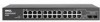
...can be disabled. On the left to indicate the port status. PowerConnect 2724 Back Panel 17 PowerConnect 2724 Front Panel On the front panel there are 24 ports which ...1 to 24, top down and left side of a combo port can switch from the RJ-45 to the SFP (or vice versa) without resetting the device. There are logical ports with two physical connections: • An... Plugable) ports, designated as ports 23 and 24, for swappable optical transceiver, which indicates the Ethernet switch operational status. If both RJ-45 and SFP ports are determined by the physical connection used. A...
...can be disabled. On the left to indicate the port status. PowerConnect 2724 Back Panel 17 PowerConnect 2724 Front Panel On the front panel there are 24 ports which ...1 to 24, top down and left side of a combo port can switch from the RJ-45 to the SFP (or vice versa) without resetting the device. There are logical ports with two physical connections: • An... Plugable) ports, designated as ports 23 and 24, for swappable optical transceiver, which indicates the Ethernet switch operational status. If both RJ-45 and SFP ports are determined by the physical connection used. A...

User's Guide
Page 18
... 1000BASE-SX or 1000BASE-LX connection. NOTE: Only one of the two physical connections of a combo port can switch from the RJ-45 to the SFP (or vice versa) without resetting the device. PowerConnect 2748 Back Panel 18 The following figure illustrates the back panel of the front panel is powered on a combo...
... 1000BASE-SX or 1000BASE-LX connection. NOTE: Only one of the two physical connections of a combo port can switch from the RJ-45 to the SFP (or vice versa) without resetting the device. PowerConnect 2748 Back Panel 18 The following figure illustrates the back panel of the front panel is powered on a combo...
User's Guide
Page 23
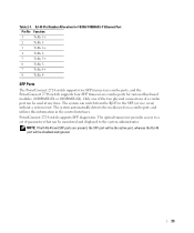
SFP Ports The PowerConnect 2724 switch supports two SFP transceivers combo ports, and the PowerConnect 2748 switch supports four SFP transceivers combo ports for 10/100/ 1000BASE-T Ethernet Port Pin No Function 1 TxRx 1+ 2 TxRx 1- 3 TxRx 2+ 4 TxRx 2- 5 TxRx 3+ 6 TxRx 3- 7 TxRx 4+.... 23 The optical transceiver provides access to the SFP (or vice versa) without a system reset. RJ-45 Pin Number Allocation for various fiber-based modules (1000BASE-SX or 1000BASE-LX). PowerConnect 2724 switch supports SFP diagnostics. NOTE: If both RJ-45 and SFP ports are present, the SFP ...
SFP Ports The PowerConnect 2724 switch supports two SFP transceivers combo ports, and the PowerConnect 2748 switch supports four SFP transceivers combo ports for 10/100/ 1000BASE-T Ethernet Port Pin No Function 1 TxRx 1+ 2 TxRx 1- 3 TxRx 2+ 4 TxRx 2- 5 TxRx 3+ 6 TxRx 3- 7 TxRx 4+.... 23 The optical transceiver provides access to the SFP (or vice versa) without a system reset. RJ-45 Pin Number Allocation for various fiber-based modules (1000BASE-SX or 1000BASE-LX). PowerConnect 2724 switch supports SFP diagnostics. NOTE: If both RJ-45 and SFP ports are present, the SFP ...
User's Guide
Page 44
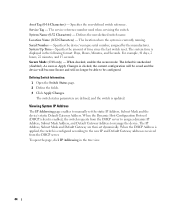
... Host Configuration Protocol (DHCP) client is displayed in the tree view. 44 Specifies the user-defined switch reference. Defines the user-defined switch name. Serial Number - Specifies the amount of time since the last switch reset. The switch status parameters are then set the static IP Address, Subnet Mask and the device's static Default Gateway...
... Host Configuration Protocol (DHCP) client is displayed in the tree view. 44 Specifies the user-defined switch reference. Defines the user-defined switch name. Serial Number - Specifies the amount of time since the last switch reset. The switch status parameters are then set the static IP Address, Subnet Mask and the device's static Default Gateway...
User's Guide
Page 46
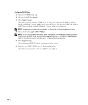
...Change the DHCP to the new DHCP client address. 46 Record the updated dynamic fields. 4 Check the box for Apply DHCP Address. The switch is reconnected to Enable. 3 Click Apply Changes. NOTE: The displayed values are not configured to -Default recovers the device default configuration. 5 Click... Apply Changes. A reset-to the device. The dynamic DHCP IP Address, DHCP Subnet Mask, and DHCP Default Gateway Address are saved and configured in the device only...
...Change the DHCP to the new DHCP client address. 46 Record the updated dynamic fields. 4 Check the box for Apply DHCP Address. The switch is reconnected to Enable. 3 Click Apply Changes. NOTE: The displayed values are not configured to -Default recovers the device default configuration. 5 Click... Apply Changes. A reset-to the device. The dynamic DHCP IP Address, DHCP Subnet Mask, and DHCP Default Gateway Address are saved and configured in the device only...

User's Guide
Page 50
...Apply Changes. Current - VLAN Membership Ports can have the following values: T - U - The interface is for Jumbo Frames support. After Reset - Figure 6-5. The switch supports the mapping of a VLAN. Indicates the Jumbo Frames status after power cycling. The VLAN Membership page also displays the VLAN ID currently.... Packets forwarded by the interface are assigned VLAN membership by the interface are enabled on the device after the next time the switch is a member of 4094 VLAN IDs up to statically create a new VLAN. Shows what the current status is a VLAN member...
...Apply Changes. Current - VLAN Membership Ports can have the following values: T - U - The interface is for Jumbo Frames support. After Reset - Figure 6-5. The switch supports the mapping of a VLAN. Indicates the Jumbo Frames status after power cycling. The VLAN Membership page also displays the VLAN ID currently.... Packets forwarded by the interface are assigned VLAN membership by the interface are enabled on the device after the next time the switch is a member of 4094 VLAN IDs up to statically create a new VLAN. Shows what the current status is a VLAN member...
User's Guide
Page 56
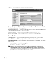
... download via HTTP - It is recommended to designate that the nonactive image will become the active image after reset, and then to be downloaded. Download via the HTTP protocol. Indicates the file to reset the device following the download. Destination File Name - The window closes automatically when the download is downloaded. The... Boot file NOTE: The image file overwrites the non-active image. Download via the TFTP server. The possible field values are grayed out. File Download (PowerConnect 2748 Switch Configuration) Firmware Download -
... download via HTTP - It is recommended to designate that the nonactive image will become the active image after reset, and then to be downloaded. Download via the HTTP protocol. Indicates the file to reset the device following the download. Destination File Name - The window closes automatically when the download is downloaded. The... Boot file NOTE: The image file overwrites the non-active image. Download via the TFTP server. The possible field values are grayed out. File Download (PowerConnect 2748 Switch Configuration) Firmware Download -


