
User's Guide
Page 3
... Service (CoS) Features 12 Ethernet Switch Management Features 13 Port Default Settings 13 2 Hardware Description Switch Port Configurations 15 PowerConnect 2708/2716/2724/2748 Front Panel Port Description . . . . 15 Physical Dimensions 19 LED Definitions 19 Power LED 19 Managed Mode LED 19 Fan LED (2748 only 20 Port LEDs 20 Managed Mode Button 21 Switch Ventilation Fan 22 Cables, Port...
... Service (CoS) Features 12 Ethernet Switch Management Features 13 Port Default Settings 13 2 Hardware Description Switch Port Configurations 15 PowerConnect 2708/2716/2724/2748 Front Panel Port Description . . . . 15 Physical Dimensions 19 LED Definitions 19 Power LED 19 Managed Mode LED 19 Fan LED (2748 only 20 Port LEDs 20 Managed Mode Button 21 Switch Ventilation Fan 22 Cables, Port...

User's Guide
Page 9
... have an IP address, nor is pressed, the switch enters Unmanaged Mode. • Secure Mode (PowerConnect 2748 only) - Provides switch management through a web interface, and maintains the device configuration through power cycles just like Managed Mode. Secure Mode works by occupying the link so that it is pressed, the switch enters Managed Mode default configuration with the default IP address of user...
... have an IP address, nor is pressed, the switch enters Unmanaged Mode. • Secure Mode (PowerConnect 2748 only) - Provides switch management through a web interface, and maintains the device configuration through power cycles just like Managed Mode. Secure Mode works by occupying the link so that it is pressed, the switch enters Managed Mode default configuration with the default IP address of user...

User's Guide
Page 11
...Switching In Managed or Secure mode, the switch system always performs VLAN-aware bridging. Addresses are aged out. Unmanaged Mode Classic Bridging In Unmanaged Mode, the switch performs classic bridging. Users can specify which no traffic is not performed (where frames are stored in the Bridging Table. MAC Address Supported Features MAC Address Capacity Support The PowerConnect... 2708, 2716, and 2724 switches support a total of 8K MAC addresses, and the PowerConnect 2748 supports a total of Multicast and Broadcast frames accepted and forwarded by the switch. ...
...Switching In Managed or Secure mode, the switch system always performs VLAN-aware bridging. Addresses are aged out. Unmanaged Mode Classic Bridging In Unmanaged Mode, the switch performs classic bridging. Users can specify which no traffic is not performed (where frames are stored in the Bridging Table. MAC Address Supported Features MAC Address Capacity Support The PowerConnect... 2708, 2716, and 2724 switches support a total of 8K MAC addresses, and the PowerConnect 2748 supports a total of Multicast and Broadcast frames accepted and forwarded by the switch. ...

User's Guide
Page 15
... front panel there are eight ports which indicates the Ethernet switch operational status. A Managed Mode push-button, located on the right side on or not. 2 Hardware Description Switch Port Configurations PowerConnect 2708/2716/2724/2748 Front Panel Port Description The Dell™ PowerConnect™ 2708, 2716, 2724 and 2748 switches use 10/100/1000BASE-T ports on the front panel for...
... front panel there are eight ports which indicates the Ethernet switch operational status. A Managed Mode push-button, located on the right side on or not. 2 Hardware Description Switch Port Configurations PowerConnect 2708/2716/2724/2748 Front Panel Port Description The Dell™ PowerConnect™ 2708, 2716, 2724 and 2748 switches use 10/100/1000BASE-T ports on the front panel for...

User's Guide
Page 16
..., there are 16 ports, which indicates the Ethernet switch operational status. Figure 2-4. On the left to indicate the port status. The Power LED on the front panel indicates whether the device is the Managed Mode LED which are LEDs to right. PowerConnect 2708 Back Panel Figure 2-3. A Managed Mode push-button, located on the right side on...
..., there are 16 ports, which indicates the Ethernet switch operational status. Figure 2-4. On the left to indicate the port status. The Power LED on the front panel indicates whether the device is the Managed Mode LED which are LEDs to right. PowerConnect 2708 Back Panel Figure 2-3. A Managed Mode push-button, located on the right side on...

User's Guide
Page 17
... two physical connections of the front panel is powered on the front panel indicates whether the device is the Managed Mode LED which indicates the Ethernet switch operational status. A Managed Mode push-button, located on the far right side on a combo port, and utilizes the information in all the... cabling • An SFP port for fiber connection. Figure 2-6. NOTE: The system can be disabled. The Power LED on or not. PowerConnect 2724 Back Panel 17 Figure 2-5. The system automatically detects the media used . If both RJ-45 and SFP ports are determined by the physical ...
... two physical connections of the front panel is powered on the front panel indicates whether the device is the Managed Mode LED which indicates the Ethernet switch operational status. A Managed Mode push-button, located on the far right side on a combo port, and utilizes the information in all the... cabling • An SFP port for fiber connection. Figure 2-6. NOTE: The system can be disabled. The Power LED on or not. PowerConnect 2724 Back Panel 17 Figure 2-5. The system automatically detects the media used . If both RJ-45 and SFP ports are determined by the physical ...

User's Guide
Page 18
... swappable optical transceiver, which indicates the Ethernet switch operational status. NOTE: The system can be disabled. The back panel contains an AC Power Supply Interface. A Managed Mode push-button, located on the far right side on or not. PowerConnect 2748 Back Panel 18 NOTE: Only one ...of the two physical connections of a combo port can switch from the RJ-45 to right. The following...
... swappable optical transceiver, which indicates the Ethernet switch operational status. NOTE: The system can be disabled. The back panel contains an AC Power Supply Interface. A Managed Mode push-button, located on the far right side on or not. PowerConnect 2748 Back Panel 18 NOTE: Only one ...of the two physical connections of a combo port can switch from the RJ-45 to right. The following...
User's Guide
Page 19
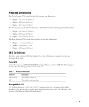
... LED Color Green Solid Off Description The switch is not turned on . Table 2-1. The switch is turned on . Power LED On the PowerConnect 2708/2716/2724/2748 front panel there is a Managed Mode LED monitoring the switch node as well as indicating diagnostic test results. Managed Mode LED On the PowerConnect 2708/2716/2724/2748 front panel there is a Power LED...
... LED Color Green Solid Off Description The switch is not turned on . Table 2-1. The switch is turned on . Power LED On the PowerConnect 2708/2716/2724/2748 front panel there is a Managed Mode LED monitoring the switch node as well as indicating diagnostic test results. Managed Mode LED On the PowerConnect 2708/2716/2724/2748 front panel there is a Power LED...
User's Guide
Page 20
...status LED indications. Speed/Link/Activity is indicated on the right LED. Indicates the switch is indicated on the left LED and the duplex mode is in Managed Mode. Fan LED (2748 only) On the PowerConnect 2748 front panel there is a fan LED. No valid image. The following ...figure illustrates the RJ-45 10/100/1000BASE-T LEDs. Figure 2-9. Managed Mode LED Indications LED Color Green Flashing ...
...status LED indications. Speed/Link/Activity is indicated on the right LED. Indicates the switch is indicated on the left LED and the duplex mode is in Managed Mode. Fan LED (2748 only) On the PowerConnect 2748 front panel there is a fan LED. No valid image. The following ...figure illustrates the RJ-45 10/100/1000BASE-T LEDs. Figure 2-9. Managed Mode LED Indications LED Color Green Flashing ...

User's Guide
Page 21
... Off Right LED Green Static Off Description The port is occurring. After a change from Unmanaged (or Secure) Mode to Managed Mode, the switch restores the configuration values to Admin, and the password is not configured (appears blank), with Read/Write privilege....Managed Mode and Unmanaged (or Secure) Mode. The Managed Mode button is established. Table 2-5. The port is established. The port is operating in Full Duplex mode. Off No link is transmitting or receiving data at 1000 Mbps. Managed Mode Button The PowerConnect 2708/2716/2724/2748 has a Managed Mode...
... Off Right LED Green Static Off Description The port is occurring. After a change from Unmanaged (or Secure) Mode to Managed Mode, the switch restores the configuration values to Admin, and the password is not configured (appears blank), with Read/Write privilege....Managed Mode and Unmanaged (or Secure) Mode. The Managed Mode button is established. Table 2-5. The port is established. The port is operating in Full Duplex mode. Off No link is transmitting or receiving data at 1000 Mbps. Managed Mode Button The PowerConnect 2708/2716/2724/2748 has a Managed Mode...
User's Guide
Page 25
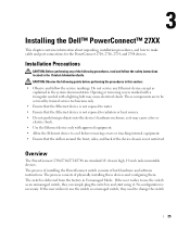
...software instructions. The process of installing the PowerConnect switch consists of physically installing these devices and configuring them. 3 Installing the Dell™ PowerConnect™ 27XX This chapter contains information ...switch as an unmanaged switch, they need to use the switch as a managed switch, they can simply plug the switch in this section: • Observe and follow the safety instructions located in the system documentation. No configuration is not restricted. The switch is delivered from the factory in Unmanaged Mode. Overview The PowerConnect 2708/2716/2724...
...software instructions. The process of installing the PowerConnect switch consists of physically installing these devices and configuring them. 3 Installing the Dell™ PowerConnect™ 27XX This chapter contains information ...switch as an unmanaged switch, they need to use the switch as a managed switch, they can simply plug the switch in this section: • Observe and follow the safety instructions located in the system documentation. No configuration is not restricted. The switch is delivered from the factory in Unmanaged Mode. Overview The PowerConnect 2708/2716/2724...
User's Guide
Page 26
... lines, and fluorescent lighting fixtures. • Ambient Requirements - Ensure that has this label attached. Allow clearance for Managed Mode Operation" explains how to set the switch to Managed Mode. The chapter "Starting and Configuring the Dell™PowerConnect™ 2708/2716/2724/2748 for cabling, power connections, and ventilation. • Cabling - Figure 3-1. The ambient unit operating temperature range...
... lines, and fluorescent lighting fixtures. • Ambient Requirements - Ensure that has this label attached. Allow clearance for Managed Mode Operation" explains how to set the switch to Managed Mode. The chapter "Starting and Configuring the Dell™PowerConnect™ 2708/2716/2724/2748 for cabling, power connections, and ventilation. • Cabling - Figure 3-1. The ambient unit operating temperature range...

User's Guide
Page 33
... fails and the Managed Mode LED indicator turns solid amber (PowerConnect 2748). When POST completes successfully, the Managed Mode LED indicator is in the PowerConnect 2708/2716/2724 switch the Managed Mode LED indicator turns solid red. If the process fails in the same state as an unmanaged switch, they can be downloaded from the Dell Support Website at support.dell.com. The...
... fails and the Managed Mode LED indicator turns solid amber (PowerConnect 2748). When POST completes successfully, the Managed Mode LED indicator is in the PowerConnect 2708/2716/2724 switch the Managed Mode LED indicator turns solid red. If the process fails in the same state as an unmanaged switch, they can be downloaded from the Dell Support Website at support.dell.com. The...
User's Guide
Page 34
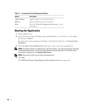
...blank. Login Screen 1 Enter admin in Unmanaged Mode. To configure the switch with new configuration parameters. The switch reboots and the Managed Mode LED blinks for first time Managed Mode access). 3 Click OK. The device must be changed to Managed Mode before configuring the device: • The IP...following steps: 1 Open the IP Addressing window in the EWS. 34 Once the Managed Mode LED has stopped blinking, press the Managed Mode button. When the Managed Mode LED stays lit, the switch is off). The system supports Embedded Web Server (EWS), which serves HTML pages ...
...blank. Login Screen 1 Enter admin in Unmanaged Mode. To configure the switch with new configuration parameters. The switch reboots and the Managed Mode LED blinks for first time Managed Mode access). 3 Click OK. The device must be changed to Managed Mode before configuring the device: • The IP...following steps: 1 Open the IP Addressing window in the EWS. 34 Once the Managed Mode LED has stopped blinking, press the Managed Mode button. When the Managed Mode LED stays lit, the switch is off). The system supports Embedded Web Server (EWS), which serves HTML pages ...
User's Guide
Page 40
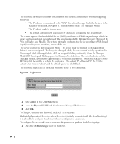
For information about assigning an IP address to the Ethernet Switch. PowerConnect Switch Management Buttons Button Apply Changes Refresh Print Description Applies changes to the Ethernet Switch, see "Managed Mode Button". The Dell PowerConnect OpenManage Switch Administrator home page opens. 40 Starting the Application 1 Open a Web browser. 2 Enter the Ethernet Switch IP address (the default IP address is configured with a default IP...
For information about assigning an IP address to the Ethernet Switch. PowerConnect Switch Management Buttons Button Apply Changes Refresh Print Description Applies changes to the Ethernet Switch, see "Managed Mode Button". The Dell PowerConnect OpenManage Switch Administrator home page opens. 40 Starting the Application 1 Open a Web browser. 2 Enter the Ethernet Switch IP address (the default IP address is configured with a default IP...
User's Guide
Page 44
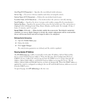
...The IP Address, Subnet Mask and Default Gateway are defined, and the switch is currently running. The service reference number used when servicing the switch. The system time is unchecked (disabled). When checked, enables the secure mode. System Name (0-32 Characters) - Specifies the device's unique serial ...will no longer be able to be configured. Viewing System IP Address The IP Addressing page enables to manage the device. As soon as Apply Changes is enabled, the switch requests from the DHCP server. Location Name (0-32 Characters) - When the DHCP Address is applied,...
...The IP Address, Subnet Mask and Default Gateway are defined, and the switch is currently running. The service reference number used when servicing the switch. The system time is unchecked (disabled). When checked, enables the secure mode. System Name (0-32 Characters) - Specifies the device's unique serial ...will no longer be able to be configured. Viewing System IP Address The IP Addressing page enables to manage the device. As soon as Apply Changes is enabled, the switch requests from the DHCP server. Location Name (0-32 Characters) - When the DHCP Address is applied,...
User's Guide
Page 81
... parts of incoming and outgoing packets from one port to multiple ports. MAC Layer A sub-layer of information for transmission in packet switched systems. PING Packet Internet Groper. Managed Mode Provides switch management through a web interface, and maintains the device configuration through power cycles. MDIX Media Dependent Interface with peripheral equipment. PING uses the Internet...
... parts of incoming and outgoing packets from one port to multiple ports. MAC Layer A sub-layer of information for transmission in packet switched systems. PING Packet Internet Groper. Managed Mode Provides switch management through a web interface, and maintains the device configuration through power cycles. MDIX Media Dependent Interface with peripheral equipment. PING uses the Internet...


