

Setup and Quick Reference Guide
Page 39
...you begin any of the procedures in standby mode. Troubleshooting CAUTION: To guard against the likelihood of electric shock, laceration by moving fan blades, or other expected injuries, always unplug your computer. Beep Codes Your computer might be malfunctioning or incorrectly installed. •... from the electrical outlet before opening the cover. For additional safety best practices information, see the Regulatory Compliance Homepage at www.dell.com/regulatory_compliance. Press a key on and blinks or remains solid to resume normal operation. Tools Power Lights The two-color ...
...you begin any of the procedures in standby mode. Troubleshooting CAUTION: To guard against the likelihood of electric shock, laceration by moving fan blades, or other expected injuries, always unplug your computer. Beep Codes Your computer might be malfunctioning or incorrectly installed. •... from the electrical outlet before opening the cover. For additional safety best practices information, see the Regulatory Compliance Homepage at www.dell.com/regulatory_compliance. Press a key on and blinks or remains solid to resume normal operation. Tools Power Lights The two-color ...
Setup and Quick Reference Guide
Page 47
CPU FAN FAILURE - HA R D -DISK DRIVE FAILURE - Check cables, swap hard disks, or see "Contacting Dell" on page 71 for assistance. No bootable partition on hard drive, or the hard drive cable is loose, or no bootable device exists. &#... the USB device. Possible hard drive failure during hard drive POST. USB OVER CURRENT ERROR - Replace processor fan. N O B O O T D E V I L U R E - Disconnect the USB device. DELL RECOMMENDS THAT YOU BACK UP YOUR DATA REGULARLY. Processor fan failure. A chip on the system board might be enabled or disabled in the search field and press to...
CPU FAN FAILURE - HA R D -DISK DRIVE FAILURE - Check cables, swap hard disks, or see "Contacting Dell" on page 71 for assistance. No bootable partition on hard drive, or the hard drive cable is loose, or no bootable device exists. &#... the USB device. Possible hard drive failure during hard drive POST. USB OVER CURRENT ERROR - Replace processor fan. N O B O O T D E V I L U R E - Disconnect the USB device. DELL RECOMMENDS THAT YOU BACK UP YOUR DATA REGULARLY. Processor fan failure. A chip on the system board might be enabled or disabled in the search field and press to...
Service Manual
Page 6
8 I/O Panel 89 Removing the I/O Panel 89 Replacing the I/O Panel 91 9 Fan 93 Removing the Chassis Fan 93 Replacing the Chassis Fan 97 10 Processor Heat Sink/Fan Assembly . . . 99 Removing the Processor Heat Sink/Fan Assembly . . . 99 Replacing the Processor Heat Sink/Fan Assembly 101 11 Memory Module(s 103 Removing Memory Modules 103 Replacing or Adding a Memory Module 104 12 Power Supply 107 Removing the Power Supply 107 Replacing the Power Supply 109 DC Power Supply Connectors 110 DC Power Supply Connector Pin Assignments . . . . 112 6 Contents
8 I/O Panel 89 Removing the I/O Panel 89 Replacing the I/O Panel 91 9 Fan 93 Removing the Chassis Fan 93 Replacing the Chassis Fan 97 10 Processor Heat Sink/Fan Assembly . . . 99 Removing the Processor Heat Sink/Fan Assembly . . . 99 Replacing the Processor Heat Sink/Fan Assembly 101 11 Memory Module(s 103 Removing Memory Modules 103 Replacing or Adding a Memory Module 104 12 Power Supply 107 Removing the Power Supply 107 Replacing the Power Supply 109 DC Power Supply Connectors 110 DC Power Supply Connector Pin Assignments . . . . 112 6 Contents

Service Manual
Page 12
...connected and that the drive is installed properly and partitioned as a boot device. • Enter the system setup program (see "Contacting Dell" on page 22). Hardware Troubleshooter If a device is either the operating system or the program that the boot sequence information is not ...listed in BIOS setup. Replace the battery (see "Keyboard Problems" on page 137). DELL RECOMMENDS THAT YOU BACK UP YOUR DATA REGULARLY. Replace the heat sink/fan assembly (see the documentation for either not detected during hard drive boot test. S.M.A.R.T error, possible hard ...
...connected and that the drive is installed properly and partitioned as a boot device. • Enter the system setup program (see "Contacting Dell" on page 22). Hardware Troubleshooter If a device is either the operating system or the program that the boot sequence information is not ...listed in BIOS setup. Replace the battery (see "Keyboard Problems" on page 137). DELL RECOMMENDS THAT YOU BACK UP YOUR DATA REGULARLY. Replace the heat sink/fan assembly (see the documentation for either not detected during hard drive boot test. S.M.A.R.T error, possible hard ...
Service Manual
Page 30
...R C A B L E C O N N E C T I N D O W S V O L U M E C O N T R O L - See the setup diagram supplied with another device, such as shown on the media player(s) has not been turned down or off nearby fans, fluorescent lights, or halogen lamps to the card. A D J U S T T H E W I O N S - E L I M I N A T E P O S S I B L E I O N - No sound from the speakers is automatically disabled when headphones are ...Regulatory Compliance Homepage at www.dell.com/regulatory_compliance. E N S U R E T H A T T H E S U B W O O F E R A N D T H E S P E A K E R S A R E T U R N E D O N - Sound from headphones...
...R C A B L E C O N N E C T I N D O W S V O L U M E C O N T R O L - See the setup diagram supplied with another device, such as shown on the media player(s) has not been turned down or off nearby fans, fluorescent lights, or halogen lamps to the card. A D J U S T T H E W I O N S - E L I M I N A T E P O S S I B L E I O N - No sound from the speakers is automatically disabled when headphones are ...Regulatory Compliance Homepage at www.dell.com/regulatory_compliance. E N S U R E T H A T T H E S U B W O O F E R A N D T H E S P E A K E R S A R E T U R N E D O N - Sound from headphones...
Service Manual
Page 32
... running the monitor self-test. See the monitor documentation for instructions on the computer and the monitor and adjust the monitor brightness and contrast controls. M O V E T H E S U B W O O F E R A W A Y F R O M T H E M O N I G H T S - Fans, fluorescent lights, halogen lamps, and other electrical devices can cause the screen image to change or click the Display icon. 3 Try different settings for the...
... running the monitor self-test. See the monitor documentation for instructions on the computer and the monitor and adjust the monitor brightness and contrast controls. M O V E T H E S U B W O O F E R A W A Y F R O M T H E M O N I G H T S - Fans, fluorescent lights, halogen lamps, and other electrical devices can cause the screen image to change or click the Display icon. 3 Try different settings for the...
Service Manual
Page 37
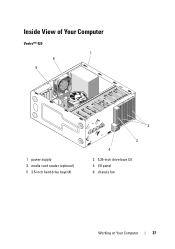
Inside View of Your Computer Vostro™ 420 1 6 5 1 power supply 3 media card reader (optional) 5 3.5-inch hard drive bays (4) 2 3 4 2 5.25-inch drive bays (3) 4 I/O panel 6 chassis fan Working on Your Computer 37
Inside View of Your Computer Vostro™ 420 1 6 5 1 power supply 3 media card reader (optional) 5 3.5-inch hard drive bays (4) 2 3 4 2 5.25-inch drive bays (3) 4 I/O panel 6 chassis fan Working on Your Computer 37
Service Manual
Page 38
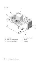
Vostro 220 1 6 5 2 3 1 power supply 3 media card reader (optional) 5 3.5-inch hard drive bays (2) 4 2 5.25-inch drive bays (2) 4 I/O panel 6 chassis fan 38 Working on Your Computer
Vostro 220 1 6 5 2 3 1 power supply 3 media card reader (optional) 5 3.5-inch hard drive bays (2) 4 2 5.25-inch drive bays (2) 4 I/O panel 6 chassis fan 38 Working on Your Computer
Service Manual
Page 39
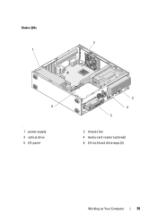
Vostro 220s 2 1 6 ' 1 power supply 3 optical drive 5 I/O panel 3 4 5 2 chassis fan 4 media card reader (optional) 6 3.5-inch hard drive bays (2) Working on Your Computer 39
Vostro 220s 2 1 6 ' 1 power supply 3 optical drive 5 I/O panel 3 4 5 2 chassis fan 4 media card reader (optional) 6 3.5-inch hard drive bays (2) Working on Your Computer 39

Service Manual
Page 41
...Express x1 connector (PCIE_X1 2) 25 audio connectors 28 USB ports (2) and E-SATA connector 31 video (VGA) and parallel ports 2 processor heat sink/fan assembly power 5 battery socket 8 serial ATA hard drive connector (SATA2) 11 serial ATA 5.25-drive connector (SATA5) 14 USB1 connector (from front ...panel) 17 audio connector (F_AUDIO) 20 PCI connector (PCI2) 23 PCI Express x16 connector (PCIE_x16) 26 one LAN and two USB ports 29 chassis fan connector 32 PS/2 mouse and keyboard connectors 3 memory module connectors (4) (DIMM_1, DIMM_2, DIMM_3, DIMM_4) 6 serial ATA 5.25-inch drive connector (...
...Express x1 connector (PCIE_X1 2) 25 audio connectors 28 USB ports (2) and E-SATA connector 31 video (VGA) and parallel ports 2 processor heat sink/fan assembly power 5 battery socket 8 serial ATA hard drive connector (SATA2) 11 serial ATA 5.25-drive connector (SATA5) 14 USB1 connector (from front ...panel) 17 audio connector (F_AUDIO) 20 PCI connector (PCI2) 23 PCI Express x16 connector (PCIE_x16) 26 one LAN and two USB ports 29 chassis fan connector 32 PS/2 mouse and keyboard connectors 3 memory module connectors (4) (DIMM_1, DIMM_2, DIMM_3, DIMM_4) 6 serial ATA 5.25-inch drive connector (...

Service Manual
Page 43
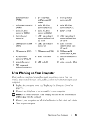
... 4 main power connector (PWR1) 7 serial ATA drive connector (SATA3) 10 front I/O panel connector 13 CMOS jumper (CLEAR CMOS) 2 processor heat sink/fan assembly power 5 serial ATA drive connector (SATA2) 8 serial ATA drive connector (SATA0) 11 USB1 system board connector (from front I/O panel) 14 USB3... system board connector 16 PCI connector (PCI1) 17 PCI connector (PCI2) 19 PCI Express x1 connector (PCIE_X1) 22 chassis fan power 25 PS/2 mouse and keyboard connectors 20 audio connectors 23 USB ports (2) 3 memory module connectors (2) 6 serial ATA drive connector (SATA1) ...
... 4 main power connector (PWR1) 7 serial ATA drive connector (SATA3) 10 front I/O panel connector 13 CMOS jumper (CLEAR CMOS) 2 processor heat sink/fan assembly power 5 serial ATA drive connector (SATA2) 8 serial ATA drive connector (SATA0) 11 USB1 system board connector (from front I/O panel) 14 USB3... system board connector 16 PCI connector (PCI1) 17 PCI connector (PCI2) 19 PCI Express x1 connector (PCIE_X1) 22 chassis fan power 25 PS/2 mouse and keyboard connectors 20 audio connectors 23 USB ports (2) 3 memory module connectors (2) 6 serial ATA drive connector (SATA1) ...
Service Manual
Page 45
... 4 main power connector (PWR1) 7 serial ATA drive connector (SATA3) 10 front I/O panel connector 13 CMOS jumper (CLEAR CMOS) 2 processor heat sink/fan assembly power 5 serial ATA drive connector (SATA2) 8 serial ATA drive connector (SATA0) 11 USB1 system board connector (from front I/O panel) 14 USB3 ...system board connector 16 PCI connector (PCI1) 17 PCI connector (PCI2) 19 PCI Express x1 connector (PCIE_X1) 22 chassis fan power 25 PS/2 mouse and keyboard connectors 20 audio connectors 23 USB ports (2) 3 memory module connectors (2) 6 serial ATA drive connector (SATA1)...
... 4 main power connector (PWR1) 7 serial ATA drive connector (SATA3) 10 front I/O panel connector 13 CMOS jumper (CLEAR CMOS) 2 processor heat sink/fan assembly power 5 serial ATA drive connector (SATA2) 8 serial ATA drive connector (SATA0) 11 USB1 system board connector (from front I/O panel) 14 USB3 ...system board connector 16 PCI connector (PCI1) 17 PCI connector (PCI2) 19 PCI Express x1 connector (PCIE_X1) 22 chassis fan power 25 PS/2 mouse and keyboard connectors 20 audio connectors 23 USB ports (2) 3 memory module connectors (2) 6 serial ATA drive connector (SATA1)...
Service Manual
Page 93
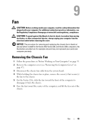
... the Vostro 420, Vostro 220, and Vostro 220s computers; Fan CAUTION: Before working inside your computer, read the safety information that secure(s) the fan to the chassis. 5 For the Vostro 220s, slide the fan toward the center of the computer, and lift the fan out ...fan cable from the system board. 4 While holding the chassis fan in place, remove the screw(s) that shipped with your particular computer precisely. For additional safety best practices information, see "Removing the Computer Cover" on page 35. 2 Remove the computer cover (see the Regulatory Compliance Homepage at www.dell...
... the Vostro 420, Vostro 220, and Vostro 220s computers; Fan CAUTION: Before working inside your computer, read the safety information that secure(s) the fan to the chassis. 5 For the Vostro 220s, slide the fan toward the center of the computer, and lift the fan out ...fan cable from the system board. 4 While holding the chassis fan in place, remove the screw(s) that shipped with your particular computer precisely. For additional safety best practices information, see "Removing the Computer Cover" on page 35. 2 Remove the computer cover (see the Regulatory Compliance Homepage at www.dell...
Service Manual
Page 97
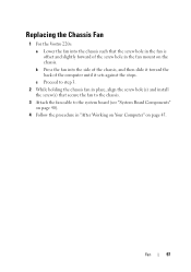
... 4 Follow the procedure in "After Working on Your Computer" on the chassis. Fan 97 b Press the fan into the chassis such that secure the fan to the chassis. 3 Attach the fan cable to step 3. 2 While holding the chassis fan in place, align the screw hole(s) and install the screw(s) that the screw ...hole in the fan is offset and slightly forward of the computer until it toward the back of the screw hole in the fan mount on page 45. Replacing the Chassis Fan 1 For the Vostro 220s: a Lower the fan into the side of the chassis, and then slide ...
... 4 Follow the procedure in "After Working on Your Computer" on the chassis. Fan 97 b Press the fan into the chassis such that secure the fan to the chassis. 3 Attach the fan cable to step 3. 2 While holding the chassis fan in place, align the screw hole(s) and install the screw(s) that the screw ...hole in the fan is offset and slightly forward of the computer until it toward the back of the screw hole in the fan mount on page 45. Replacing the Chassis Fan 1 For the Vostro 220s: a Lower the fan into the side of the chassis, and then slide ...
Service Manual
Page 99
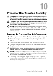
... Remove the computer cover (see the Regulatory Compliance Homepage at www.dell.com/regulatory_compliance. NOTICE: A strong thermal solution bond may become very hot during normal operation. Lay the assembly with the fan facing downward, and with your particular computer precisely. CAUTION: To guard... for removing and replacing the processor heat sink/fan assembly is for the Vostro 420, Vostro 220, and Vostro 220s computers; Processor Heat Sink/Fan Assembly 99 Be sure that it has had sufficient time to separate the heat sink/fan assembly from the system board. 4 Loosen the...
... Remove the computer cover (see the Regulatory Compliance Homepage at www.dell.com/regulatory_compliance. NOTICE: A strong thermal solution bond may become very hot during normal operation. Lay the assembly with the fan facing downward, and with your particular computer precisely. CAUTION: To guard... for removing and replacing the processor heat sink/fan assembly is for the Vostro 420, Vostro 220, and Vostro 220s computers; Processor Heat Sink/Fan Assembly 99 Be sure that it has had sufficient time to separate the heat sink/fan assembly from the system board. 4 Loosen the...

Service Manual
Page 100
1 6 5 2 3 4 1 Phillips screwdriver 3 heat sink/fan cable 5 screw holes with rubber bushings (4) 2 heat sink/fan assembly 4 system board fan connector 6 captive screws (4) 100 Processor Heat Sink/Fan Assembly
1 6 5 2 3 4 1 Phillips screwdriver 3 heat sink/fan cable 5 screw holes with rubber bushings (4) 2 heat sink/fan assembly 4 system board fan connector 6 captive screws (4) 100 Processor Heat Sink/Fan Assembly

Service Manual
Page 101
Replacing the Processor Heat Sink/Fan Assembly NOTICE: Unless a new heat sink is required for the new processor, reuse the original heat sink/fan assembly when you replace the processor. 1 Apply thermal solution to the heat sink as needed. 2 Align the four captive screws on the heat sink/fan assembly with the holes and rubber bushings on the system board. 1 2 6 3 5 4 Processor Heat Sink/Fan Assembly 101
Replacing the Processor Heat Sink/Fan Assembly NOTICE: Unless a new heat sink is required for the new processor, reuse the original heat sink/fan assembly when you replace the processor. 1 Apply thermal solution to the heat sink as needed. 2 Align the four captive screws on the heat sink/fan assembly with the holes and rubber bushings on the system board. 1 2 6 3 5 4 Processor Heat Sink/Fan Assembly 101

Service Manual
Page 102
NOTICE: Ensure that the assembly is correctly seated and secure. 4 Attach the heat sink/fan assembly cable to the system board. 1 Phillips screwdriver 3 heat sink/fan cable 5 screw holes with rubber bushings 2 heat sink/fan assembly 4 system board fan connector 6 captive screws (4) 3 Tighten the captive screws evenly to secure the heat sink/fan assembly to the system board (see "System Board Components" on page 40). 5 Follow the procedure in "After Working on Your Computer" on page 45. 102 Processor Heat Sink/Fan Assembly
NOTICE: Ensure that the assembly is correctly seated and secure. 4 Attach the heat sink/fan assembly cable to the system board. 1 Phillips screwdriver 3 heat sink/fan cable 5 screw holes with rubber bushings 2 heat sink/fan assembly 4 system board fan connector 6 captive screws (4) 3 Tighten the captive screws evenly to secure the heat sink/fan assembly to the system board (see "System Board Components" on page 40). 5 Follow the procedure in "After Working on Your Computer" on page 45. 102 Processor Heat Sink/Fan Assembly
Service Manual
Page 119
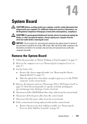
.... 8 If the system board is for the Vostro 420, Vostro 220, and Vostro 220s computers; b Slide the optical drive forward far enough ...to gain access to prevent damage from discharge of electric shock, laceration by moving fan... shipped with another system board: a Remove the processor heat sink/fan assembly (see "Removing a PCI or PCI Express Card" on ...Fan Assembly" on page 99). For additional safety best practices information, see "Removing the Chassis Support Bracket" on page 47). 3 For the Vostro 220s...
.... 8 If the system board is for the Vostro 420, Vostro 220, and Vostro 220s computers; b Slide the optical drive forward far enough ...to gain access to prevent damage from discharge of electric shock, laceration by moving fan... shipped with another system board: a Remove the processor heat sink/fan assembly (see "Removing a PCI or PCI Express Card" on ...Fan Assembly" on page 99). For additional safety best practices information, see "Removing the Chassis Support Bracket" on page 47). 3 For the Vostro 220s...

Service Manual
Page 120
... when handling the system board. 12 Carefully lift the system board out of the computer chassis and place it into antistatic packaging. 9 Disconnect the chassis fan cable from the system board. 10 Disconnect any additional cables from the system board (see "Removing the Processor" on page 125) and place it into...
... when handling the system board. 12 Carefully lift the system board out of the computer chassis and place it into antistatic packaging. 9 Disconnect the chassis fan cable from the system board. 10 Disconnect any additional cables from the system board (see "Removing the Processor" on page 125) and place it into...


