

Service Manual
Page 1
COLOR MONITOR SERVICE MANUAL CHASSIS NO. : CL-74 MODEL: 2005FPW CAUTION BEFORE SERVICING THE UNIT, READ THE SAFETY PRECAUTIONS IN THIS MANUAL.
COLOR MONITOR SERVICE MANUAL CHASSIS NO. : CL-74 MODEL: 2005FPW CAUTION BEFORE SERVICING THE UNIT, READ THE SAFETY PRECAUTIONS IN THIS MANUAL.

Service Manual
Page 2
....8 mm (16.81'') 8. CONTENTS SPECIFICATIONS 2 PRECAUTIONS 3 TIMING CHART 7 DISASSEMBLY 8 BLOCK DIAGRAM 9 DESCRIPTION OF BLOCK DIAGRAM 10 ADJUSTMENT 12 TROUBLESHOOTING GUIDE 14 WIRING DIAGRAM 18 EXPLODED VIEW 19 REPLACEMENT PARTS LIST 21 SCHEMATIC DIAGRAM 26 SPECIFICATIONS 1. OPTICAL CHARACTERISTICS 2-1. less than 3 W less than 3 W less than 3 W less than 1 W@110VAC AMBER AMBER AMBER - 6. LCD CHARACTERISTICS Type Size Pixel Pitch Color Depth Electrical Interface Surface Treatment Operating Mode Backlight Unit : TFT WSXGA LCD : 20.1inch : 0.258(H) x 0.258(V) : 8-bit...
....8 mm (16.81'') 8. CONTENTS SPECIFICATIONS 2 PRECAUTIONS 3 TIMING CHART 7 DISASSEMBLY 8 BLOCK DIAGRAM 9 DESCRIPTION OF BLOCK DIAGRAM 10 ADJUSTMENT 12 TROUBLESHOOTING GUIDE 14 WIRING DIAGRAM 18 EXPLODED VIEW 19 REPLACEMENT PARTS LIST 21 SCHEMATIC DIAGRAM 26 SPECIFICATIONS 1. OPTICAL CHARACTERISTICS 2-1. less than 3 W less than 3 W less than 3 W less than 1 W@110VAC AMBER AMBER AMBER - 6. LCD CHARACTERISTICS Type Size Pixel Pitch Color Depth Electrical Interface Surface Treatment Operating Mode Backlight Unit : TFT WSXGA LCD : 20.1inch : 0.258(H) x 0.258(V) : 8-bit...
Service Manual
Page 3
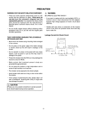
... new backlight (CCFL) or inverter circuit, must disconnect the AC adapter because high voltage appears at inverter circuit about 650Vrms. • Handle with care wires or connectors of the frame strongly or electric shock as this may result in four corners. • Do not press on the schematic diagram and the replacement parts list. Leakage Current Hot Check...
... new backlight (CCFL) or inverter circuit, must disconnect the AC adapter because high voltage appears at inverter circuit about 650Vrms. • Handle with care wires or connectors of the frame strongly or electric shock as this may result in four corners. • Do not press on the schematic diagram and the replacement parts list. Leakage Current Hot Check...

Service Manual
Page 4
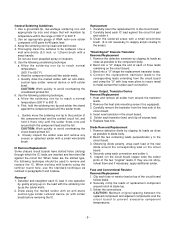
... precautions on or near this service manual, lubrication of the assembly. 3. Connecting a test substitute in not required. 6. Test high voltage only by touching a known earth ground. After removing an electrical assembly equipped with which should be used to help reduce the incidence of this service manual might be removed to prevent potential shock reasons prior to applying power to damage ES devices. 5. d. Always...
... precautions on or near this service manual, lubrication of the assembly. 3. Connecting a test substitute in not required. 6. Test high voltage only by touching a known earth ground. After removing an electrical assembly equipped with which should be used to help reduce the incidence of this service manual might be removed to prevent potential shock reasons prior to applying power to damage ES devices. 5. d. Always...
Service Manual
Page 5
... as possible to remove and replace the IC. Bend into a "U" shape the replacement transistor leads. 4. Power Output, Transistor Device Removal/Replacement 1. Diode Removal/Replacement 1. Observing diode polarity, wrap each of the circuit board. 4. Securely crimp each fuse or resistor lead at stake top. 3. Clip each connection and solder it . 3. Use a mall wire-bristle (0.5 inch, or 1.25cm) brush with solder braid. Quickly draw the...
... as possible to remove and replace the IC. Bend into a "U" shape the replacement transistor leads. 4. Power Output, Transistor Device Removal/Replacement 1. Diode Removal/Replacement 1. Observing diode polarity, wrap each of the circuit board. 4. Securely crimp each fuse or resistor lead at stake top. 3. Clip each connection and solder it . 3. Use a mall wire-bristle (0.5 inch, or 1.25cm) brush with solder braid. Quickly draw the...

Service Manual
Page 6
...board. (Use this condition is encountered. Connect insulated 20-gauge jumper wire from or "lift-off any printed circuit board will weaken the adhesive that bonds the foil to the circuit board causing the foil to ensure that is dressed so the it does not touch...opens. 2. At Other Connections Use the following procedure to repair the defective copper pattern at IC connections use the following technique to install a jumper wire on IC connections). 1. At IC Connections To repair a defective copper pattern at connections other side. Carefully crimp and solder the connections...
...board. (Use this condition is encountered. Connect insulated 20-gauge jumper wire from or "lift-off any printed circuit board will weaken the adhesive that bonds the foil to the circuit board causing the foil to ensure that is dressed so the it does not touch...opens. 2. At Other Connections Use the following procedure to repair the defective copper pattern at IC connections use the following technique to install a jumper wire on IC connections). 1. At IC Connections To repair a defective copper pattern at connections other side. Carefully crimp and solder the connections...

Service Manual
Page 8
REAR CABINET REMOVEL. 1) Remove the screws. Warning : if you lift cabinet up, power connector lead may be departed. (This time take care so that do not give damage on the module surface.) 3) Progress to left and lifts cabinet furtively and extracts latch. 4) Progress to right and extracts cabinet side latch by same method. 5) Progress to the small picture. 6) Turn upside down then lift the back cover ass'y up. -8- DISASSEMBLY 2) Please lift central inside edge of Cabinet upward with fingertip then latch will be disconnected or damaged.) Refer to bottom.
REAR CABINET REMOVEL. 1) Remove the screws. Warning : if you lift cabinet up, power connector lead may be departed. (This time take care so that do not give damage on the module surface.) 3) Progress to left and lifts cabinet furtively and extracts latch. 4) Progress to right and extracts cabinet side latch by same method. 5) Progress to the small picture. 6) Turn upside down then lift the back cover ass'y up. -8- DISASSEMBLY 2) Please lift central inside edge of Cabinet upward with fingertip then latch will be disconnected or damaged.) Refer to bottom.

Service Manual
Page 10
..., Flash-ROM IC which is provided 12V in Power Board V is provided for LCD Panel.(Only LPL) 5V in Power Board V is provided for LCD Panel.(Only AUO) 12V in the main board. - 10 - Converted power is provided for IC in Power Board V is provided for Inverter Part. The Scaler gets the video signal converted analog to digital, interpolates input to 1680 x1050 resolution signal and outputs 8-bit R, G, B signal to the digital video signal using a pixel clock...
..., Flash-ROM IC which is provided 12V in Power Board V is provided for LCD Panel.(Only LPL) 5V in Power Board V is provided for LCD Panel.(Only AUO) 12V in the main board. - 10 - Converted power is provided for IC in Power Board V is provided for Inverter Part. The Scaler gets the video signal converted analog to digital, interpolates input to 1680 x1050 resolution signal and outputs 8-bit R, G, B signal to the digital video signal using a pixel clock...

Service Manual
Page 11
... isolation. Input rectifier and filter. Output rectifier and filter. Energy Transfer. This part function is to collect the any change from DC12V to feed back the dc output changing status through a power transformer. 4. This part function is to AC 840Vrms and operate back-light lamp of...feed back to achieve the stabilized dc output voltage. 6. This part function is to make a pulse width modulation control and to provide the driver signal to power switch,to adjust the duty cycle during different AC input and output loading condition to achieve the dc output stabilized, and...
... isolation. Input rectifier and filter. Output rectifier and filter. Energy Transfer. This part function is to collect the any change from DC12V to feed back the dc output changing status through a power transformer. 4. This part function is to AC 840Vrms and operate back-light lamp of...feed back to achieve the stabilized dc output voltage. 6. This part function is to make a pulse width modulation control and to provide the driver signal to power switch,to adjust the duty cycle during different AC input and output loading condition to achieve the dc output stabilized, and...
Service Manual
Page 12
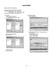
....0 User Manual Operating System: MS Windows 98, 2000, XP Port Setup: Windows 98 => Don't need setup Windows 2000, XP => Need to LCD Monitor only. 1. This program is available to Port Setup. f) Click Exit button. - 12 - EDID Read & Write 1) Run WinEDID.exe c) Remove all default number d) Add 300-3FF 2) Edit Week of Manufacture, Year of Manufacture, Serial Number a) Input User Info Data b) Click "Update" button c) Click " Write" button e) Click Start button. Port Setup a) Copy "UserPort.sys" file to "c:\WINNT\system32\drivers...
....0 User Manual Operating System: MS Windows 98, 2000, XP Port Setup: Windows 98 => Don't need setup Windows 2000, XP => Need to LCD Monitor only. 1. This program is available to Port Setup. f) Click Exit button. - 12 - EDID Read & Write 1) Run WinEDID.exe c) Remove all default number d) Add 300-3FF 2) Edit Week of Manufacture, Year of Manufacture, Serial Number a) Input User Info Data b) Click "Update" button c) Click " Write" button e) Click Start button. Port Setup a) Copy "UserPort.sys" file to "c:\WINNT\system32\drivers...
Service Manual
Page 13
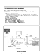
.... Cable Connection - 13 - e)WProtect : To enable write protection.(24c02) f)Blue : Allows you to set the R/G/B - 9300K value manually g)Red : Allows you to set the R/G/B - 5700K value manually h)Normal : Allows you to set the R/G/B - 6500K value manually Video Signal Generator Control Line IBM 15 Compatible PC 10 5 Not used RS232C PARALLEL PORT OFF ON 5V F C PARALLEL VGS A MONITOR B V-SYNC ST POWER Power inlet (required) 220 Power Select Switch (110V/220V) Power LED E ST Switch F V-Sync On/Off Switch (Switch...
.... Cable Connection - 13 - e)WProtect : To enable write protection.(24c02) f)Blue : Allows you to set the R/G/B - 9300K value manually g)Red : Allows you to set the R/G/B - 5700K value manually h)Normal : Allows you to set the R/G/B - 6500K value manually Video Signal Generator Control Line IBM 15 Compatible PC 10 5 Not used RS232C PARALLEL PORT OFF ON 5V F C PARALLEL VGS A MONITOR B V-SYNC ST POWER Power inlet (required) 220 Power Select Switch (110V/220V) Power LED E ST Switch F V-Sync On/Off Switch (Switch...

Service Manual
Page 14
YES CHECK DATA LINE CONNECTION(U403, U401) NO CHECK POWER BOARD, AND FIND OUT A SHORT POINT AS OPENING EACH POWER LINE NO CHECK 3.3V, 5V LINE (OPEN CHECK) NO CHECK U402 VCC X-TAL, RESET Waveforms 1 J101-#6,7,9(5V) 2 U403-#32(3.3V) 3 U401, R435, R436-#3, 4 - 14 - YES CHECK 2 U403 PIN32 Voltage (3.3V) ? YES CHECK KEY CONTROL CONNECTOR ROUTINE YES U401, R435, R436 3 PIN3, PIN4 VOLTAGE REPEATED AS PULSE SHAPE? TROUBLESHOOTING GUIDE 1. NO POWER NO POWER (POWER INDICATOR OFF) 1 CHECK J101 VOLTAGE PIN6, 7, 9(5V)?
YES CHECK DATA LINE CONNECTION(U403, U401) NO CHECK POWER BOARD, AND FIND OUT A SHORT POINT AS OPENING EACH POWER LINE NO CHECK 3.3V, 5V LINE (OPEN CHECK) NO CHECK U402 VCC X-TAL, RESET Waveforms 1 J101-#6,7,9(5V) 2 U403-#32(3.3V) 3 U401, R435, R436-#3, 4 - 14 - YES CHECK 2 U403 PIN32 Voltage (3.3V) ? YES CHECK KEY CONTROL CONNECTOR ROUTINE YES U401, R435, R436 3 PIN3, PIN4 VOLTAGE REPEATED AS PULSE SHAPE? TROUBLESHOOTING GUIDE 1. NO POWER NO POWER (POWER INDICATOR OFF) 1 CHECK J101 VOLTAGE PIN6, 7, 9(5V)?

Service Manual
Page 15
NO RASTER (OSD IS NOT DISPLAYED) - YES CHECK PULSE AS CONTACTING SCOPE PROBE TO CAUTION LABEL. NO (CONTACT PROBE TO CAUTION LABEL. CHECK MICOM DIM-ADJ PORT LIPS - 15 - LIPS NO RASTER (OSD IS NOT DISPLAYED) J101 NO PIN6, PIN7, PIN9 5V? YES REPLACE CCFL LAMP IN THE LCD MODULE Waveforms 4 J101-#10(3.3V) 5 J101-#12(3.3V) CHECK LIPS CHECK MICOM INV ON/OFF PORT. 1. YES 5 J101 PIN12 NO 3.3V? CAN YOU SEE PULSE AT YOUR SCOPE? CONFIRM BRIGHTNESS OSD CONTRL STATE. 2. 2. YES 4 J101 PIN10 NO 3.3V?
NO RASTER (OSD IS NOT DISPLAYED) - YES CHECK PULSE AS CONTACTING SCOPE PROBE TO CAUTION LABEL. NO (CONTACT PROBE TO CAUTION LABEL. CHECK MICOM DIM-ADJ PORT LIPS - 15 - LIPS NO RASTER (OSD IS NOT DISPLAYED) J101 NO PIN6, PIN7, PIN9 5V? YES REPLACE CCFL LAMP IN THE LCD MODULE Waveforms 4 J101-#10(3.3V) 5 J101-#12(3.3V) CHECK LIPS CHECK MICOM INV ON/OFF PORT. 1. YES 5 J101 PIN12 NO 3.3V? CAN YOU SEE PULSE AT YOUR SCOPE? CONFIRM BRIGHTNESS OSD CONTRL STATE. 2. 2. YES 4 J101 PIN10 NO 3.3V?

Service Manual
Page 16
... SIGNAL PINS? CHECK G4, G3 NO SOLDERING CONDITION 2. YES CHECK U607 PIN2 1.8V? CHECK X401 3. GM1501CF NO RASTER (OSD IS NOT DISPLAYED) 6 78 CHECK U608 PIN3 3.3V? AT MODE 11? TROUBLE IN U402 NO CHECK CONNECTION LINE FROM D-SUB TO U402 8 Q106-#3 - 16 - YES U402 G4, G3 OSCILLATE AS 14.318MHZ? NO RASTER (OSD IS NOT DISPLAYED) - SYNC? Q106 PIN3 IS 60Hz V- 3. YES TROUBLE IN CABLE...
... SIGNAL PINS? CHECK G4, G3 NO SOLDERING CONDITION 2. YES CHECK U607 PIN2 1.8V? CHECK X401 3. GM1501CF NO RASTER (OSD IS NOT DISPLAYED) 6 78 CHECK U608 PIN3 3.3V? AT MODE 11? TROUBLE IN U402 NO CHECK CONNECTION LINE FROM D-SUB TO U402 8 Q106-#3 - 16 - YES U402 G4, G3 OSCILLATE AS 14.318MHZ? NO RASTER (OSD IS NOT DISPLAYED) - SYNC? Q106 PIN3 IS 60Hz V- 3. YES TROUBLE IN CABLE...

Service Manual
Page 17
TROUBLE IN DPM TROUBLE IN DPM 9 10 CHECK R135, R137(SYNC) ? YES TROUBLE IN PC NO CHECK PC PC IS NOT GOING INTO DPM OFF MODE NO TROUBLE IN SIGNAL CABLE Waveforms 9 R135,R137-V-SYNC 10 R135,R137-H-SYNC - 17 - 4. YES CHECK R144(SIGNAL DETECT) ?
TROUBLE IN DPM TROUBLE IN DPM 9 10 CHECK R135, R137(SYNC) ? YES TROUBLE IN PC NO CHECK PC PC IS NOT GOING INTO DPM OFF MODE NO TROUBLE IN SIGNAL CABLE Waveforms 9 R135,R137-V-SYNC 10 R135,R137-H-SYNC - 17 - 4. YES CHECK R144(SIGNAL DETECT) ?
Service Manual
Page 18
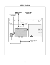
WIRING DIAGRAM Connector Ass'y P/N: 6631T11020P Connector Ass'y P/N: 6631T12007A Connector Ass'y P/N: 6631T20028G J901 J904 J401 J101 J110 CW401 CW402 CW405 CW406 Connector Ass'y P/N: 6631T11017V - 18 -
WIRING DIAGRAM Connector Ass'y P/N: 6631T11020P Connector Ass'y P/N: 6631T12007A Connector Ass'y P/N: 6631T20028G J901 J904 J401 J101 J110 CW401 CW402 CW405 CW406 Connector Ass'y P/N: 6631T11017V - 18 -

Service Manual
Page 20
...POWER, DELL 20.1"" POWER TOTAL SSE FOR LPL" METAL ASSEMBLY, FRAME MAIN ASSEMBLY-LOCAL SHIELD, INVERTER DELL[20.1""] PWB(PCB) ASSEMBLY,USB LD20FPWM SUB TOTAL DELL USB TOTAL SHIELD, USB DELL[20.1""] METAL, STAND LOCK DELL 18.1" METAL, FIX VESA LOCK LEFT DELL 18.1"" METAL, FIX VESA LOCK RIGHT DELL 18.1"" SPRING, COIL D4.0 FOR STAND L1801 KNOB, SELF RETURN STAND RELEASE BUTTON DELL 18.1""" SPRING, COIL D5.0 FOR STAND L1801 COVER, LD20FPWM BASE TOP DELL[20.1""] COVER, LD20FPWM STAND MID INNER DELL[20.1""]" COVER, LD20FPWM STAND BODY OUTER DELL[20.1""]" COVER, LD20FPWM CABLE CLIP_DELL[20.1""]" CABLE...
...POWER, DELL 20.1"" POWER TOTAL SSE FOR LPL" METAL ASSEMBLY, FRAME MAIN ASSEMBLY-LOCAL SHIELD, INVERTER DELL[20.1""] PWB(PCB) ASSEMBLY,USB LD20FPWM SUB TOTAL DELL USB TOTAL SHIELD, USB DELL[20.1""] METAL, STAND LOCK DELL 18.1" METAL, FIX VESA LOCK LEFT DELL 18.1"" METAL, FIX VESA LOCK RIGHT DELL 18.1"" SPRING, COIL D4.0 FOR STAND L1801 KNOB, SELF RETURN STAND RELEASE BUTTON DELL 18.1""" SPRING, COIL D5.0 FOR STAND L1801 COVER, LD20FPWM BASE TOP DELL[20.1""] COVER, LD20FPWM STAND MID INNER DELL[20.1""]" COVER, LD20FPWM STAND BODY OUTER DELL[20.1""]" COVER, LD20FPWM CABLE CLIP_DELL[20.1""]" CABLE...

Service Manual
Page 21
...% R/TP X7R *S *AL LOC. NO. PART NO. MAIN BOARD CAPACITORS DATE: 2004. 10. 05. REPLACEMENT PARTS LIST CAUTION: BEFORE REPLACING ANY OF THESE COMPONENTS, READ CAREFULLY THE SAFETY PRECAUTIONS IN THIS MANUAL. * NOTE : S SAFETY Mark AL ALTERNATIVE PARTS *S *AL LOC. PART NO. DESCRIPTION / SPECIFICATION C214 C215 C216 C217 C218 C219 C220 C221 C222...NP0 330PF 1608 50V 5% R/TP NP0 330PF 1608 50V 5% R/TP NP0 330PF 1608 50V 5% R/TP NP0 10000PF 50V 10% B(Y5P) 2012 47UF MVK 16V 20% R/TP(SMD) S 0.1UF 50V 10% X7R 2012 R/TP 0.1UF 50V 10% X7R 2012 R/TP 0.1UF 50V 10% X7R 2012 R/TP 0.1UF 1608 ...
...% R/TP X7R *S *AL LOC. NO. PART NO. MAIN BOARD CAPACITORS DATE: 2004. 10. 05. REPLACEMENT PARTS LIST CAUTION: BEFORE REPLACING ANY OF THESE COMPONENTS, READ CAREFULLY THE SAFETY PRECAUTIONS IN THIS MANUAL. * NOTE : S SAFETY Mark AL ALTERNATIVE PARTS *S *AL LOC. PART NO. DESCRIPTION / SPECIFICATION C214 C215 C216 C217 C218 C219 C220 C221 C222...NP0 330PF 1608 50V 5% R/TP NP0 330PF 1608 50V 5% R/TP NP0 330PF 1608 50V 5% R/TP NP0 10000PF 50V 10% B(Y5P) 2012 47UF MVK 16V 20% R/TP(SMD) S 0.1UF 50V 10% X7R 2012 R/TP 0.1UF 50V 10% X7R 2012 R/TP 0.1UF 50V 10% X7R 2012 R/TP 0.1UF 1608 ...

Service Manual
Page 23
...SGS-THOMSON 8P," "TW9905C TECHWELL 100P,LQFP T" "HY5DU283222AQ-4 HYNIX 100P,L" GM1501-CF(ESD ENHANCEMENT)DE "DELL 20.1"" LD20FPWM MICOM" S524A60X51(SCT0) SAMSUNG ELE KIA7042AP TO-92 TP 4.2 VOLT LD1117S18TR STM SOT223 R/TP TPS2042ADR...1M2012-600JT CERATEC R/TP HH-1M2012-600JT CERATEC R/TP *S *AL LOC. NO. DESCRIPTION / SPECIFICATION L607 L615 L616 L617 L618 L619 L620 L621 L622 6210TCE001Z 6210TCE001Z 6210TCE001Z 6210TCE001Z 6210TCE001Z 6210TCE001Z 6210TCE001Z 6210TCE001Z ...R/TP 75 OHM 1/10 W 5% 1608 R/TP 75 OHM 1/10 W 5% 1608 R/TP - 23 - PART NO. PART NO. DATE: 2004. 10. 05. *S *AL LOC.
...SGS-THOMSON 8P," "TW9905C TECHWELL 100P,LQFP T" "HY5DU283222AQ-4 HYNIX 100P,L" GM1501-CF(ESD ENHANCEMENT)DE "DELL 20.1"" LD20FPWM MICOM" S524A60X51(SCT0) SAMSUNG ELE KIA7042AP TO-92 TP 4.2 VOLT LD1117S18TR STM SOT223 R/TP TPS2042ADR...1M2012-600JT CERATEC R/TP HH-1M2012-600JT CERATEC R/TP *S *AL LOC. NO. DESCRIPTION / SPECIFICATION L607 L615 L616 L617 L618 L619 L620 L621 L622 6210TCE001Z 6210TCE001Z 6210TCE001Z 6210TCE001Z 6210TCE001Z 6210TCE001Z 6210TCE001Z 6210TCE001Z ...R/TP 75 OHM 1/10 W 5% 1608 R/TP 75 OHM 1/10 W 5% 1608 R/TP - 23 - PART NO. PART NO. DATE: 2004. 10. 05. *S *AL LOC.


