
Setup Guide
Page 5
...to the Internet (Optional 8 Using Your Inspiron Laptop 12 Device Status Lights 12 Right Side Features 14 Left Side Features 16 Front Side Features 18 Computer Base and Keyboard Features 19 Media Controls 20 Display Features 21 Removing and Replacing the Battery 22 Software Features 23 Solving... Problems 26 Network Problems 26 Power Problems 28 Memory Problems 29 Lockups and Software Problems 30 Dell Support Center 33 System ...
...to the Internet (Optional 8 Using Your Inspiron Laptop 12 Device Status Lights 12 Right Side Features 14 Left Side Features 16 Front Side Features 18 Computer Base and Keyboard Features 19 Media Controls 20 Display Features 21 Removing and Replacing the Battery 22 Software Features 23 Solving... Problems 26 Network Problems 26 Power Problems 28 Memory Problems 29 Lockups and Software Problems 30 Dell Support Center 33 System ...

Setup Guide
Page 30
...). 28 The display may have to remove and then reinstall the memory modules (for information on removing and replacing memory modules, see "Contacting Dell" on page 50. For assistance contact Dell, see the Service Manual on . If the AC adapter has a light, ensure that the electrical outlet is either...such as a lamp. • Check the AC adapter cable connections. You may not be malfunctioning or incorrectly installed. Press a key on the keyboard, move the pointer on the trackpad or a connected mouse, or press the power button to verify that the computer turns on properly. • ...
...). 28 The display may have to remove and then reinstall the memory modules (for information on removing and replacing memory modules, see "Contacting Dell" on page 50. For assistance contact Dell, see the Service Manual on . If the AC adapter has a light, ensure that the electrical outlet is either...such as a lamp. • Check the AC adapter cable connections. You may not be malfunctioning or incorrectly installed. Press a key on the keyboard, move the pointer on the trackpad or a connected mouse, or press the power button to verify that the computer turns on properly. • ...

Setup Guide
Page 36
... that the boot sequence information is not listed in resolving this problem, please note this system have failed at support.dell.com. Replace the battery. Possible motherboard failure or RTC battery low. CPU fan failure - Hard-disk drive failure - Alternatively you...Dell Support website at checkpoint [nnnn]. Alert! Previous attempts at booting this checkpoint and contact Dell Technical Support - Using Support Tools NOTE: If the message you could see the Service Manual on the Dell Support website at support.dell.com or see "Contacting Dell" on page 50 for assistance. Keyboard...
... that the boot sequence information is not listed in resolving this problem, please note this system have failed at support.dell.com. Replace the battery. Possible motherboard failure or RTC battery low. CPU fan failure - Hard-disk drive failure - Alternatively you...Dell Support website at checkpoint [nnnn]. Alert! Previous attempts at booting this checkpoint and contact Dell Technical Support - Using Support Tools NOTE: If the message you could see the Service Manual on the Dell Support website at support.dell.com or see "Contacting Dell" on page 50 for assistance. Keyboard...

Service Manual
Page 7
...board cable from the battery bay before you begin any of the computer). To replace the button board, remove the palm rest (see Removing the Keyboard). 4. Back to Contents Page Button Board Dell™ Inspiron™ 1525/1526 Service Manual CAUTION: Before you begin working inside the computer. NOTICE: To... prevent damage to the system board, you must remove the battery from the system board. 5. Remove the center control cover (see Replacing the Keyboard). 5. Connect the button board cable to Contents Page Back to the system board. 3. Place the button board in Before You Begin...
...board cable from the battery bay before you begin any of the computer). To replace the button board, remove the palm rest (see Removing the Keyboard). 4. Back to Contents Page Button Board Dell™ Inspiron™ 1525/1526 Service Manual CAUTION: Before you begin working inside the computer. NOTICE: To... prevent damage to the system board, you must remove the battery from the system board. 5. Remove the center control cover (see Replacing the Keyboard). 5. Connect the button board cable to Contents Page Back to the system board. 3. Place the button board in Before You Begin...
Service Manual
Page 10
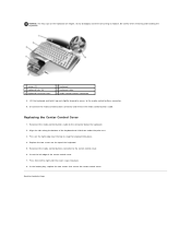
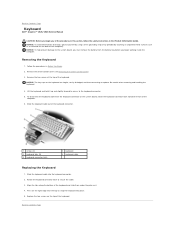
...edge of the center control cover. 7. In the battery bay, replace the two screws that secure the center control cover. Be careful when removing and handling the keyboard. 1 screws (2) 3 keyboard tabs (5) 5 keyboard connector latch 2 keyboard 4 keyboard cable 6 media control buttons connector 8. Insert the left to ...forward to access to the connector below the keyboard. 2. Press on the keyboard are fragile, easily dislodged, and time-consuming to replace. NOTICE: The key caps on the right edge near the top to snap the keyboard into place. 8. Reconnect the media control ...
...edge of the center control cover. 7. In the battery bay, replace the two screws that secure the center control cover. Be careful when removing and handling the keyboard. 1 screws (2) 3 keyboard tabs (5) 5 keyboard connector latch 2 keyboard 4 keyboard cable 6 media control buttons connector 8. Insert the left to ...forward to access to the connector below the keyboard. 2. Press on the keyboard are fragile, easily dislodged, and time-consuming to replace. NOTICE: The key caps on the right edge near the top to snap the keyboard into place. 8. Reconnect the media control ...

Service Manual
Page 11
Remove the hard drive (see Removing the Keyboard). 8. Remove the keyboard (see Removing the Hard Drive). 4. Remove the display assembly (see Removing the Processor Thermal-Cooling Assembly). 13. Back to pry up the coin-cell ... 3. Remove the processor thermal-cooling assembly (see Removing the Display Assembly). 9. Use a plastic scribe to Contents Page Coin-Cell Battery Dell™ Inspiron™ 1525/1526 Service Manual Removing the Coin-Cell Battery Replacing the Coin-Cell Battery Removing the Coin-Cell Battery CAUTION: Before you begin any of the procedures in this section...
Remove the hard drive (see Removing the Keyboard). 8. Remove the keyboard (see Removing the Hard Drive). 4. Remove the display assembly (see Removing the Processor Thermal-Cooling Assembly). 13. Back to pry up the coin-cell ... 3. Remove the processor thermal-cooling assembly (see Removing the Display Assembly). 9. Use a plastic scribe to Contents Page Coin-Cell Battery Dell™ Inspiron™ 1525/1526 Service Manual Removing the Coin-Cell Battery Replacing the Coin-Cell Battery Removing the Coin-Cell Battery CAUTION: Before you begin any of the procedures in this section...

Service Manual
Page 19
.... Remove the center control cover (see Removing the Display Assembly). 5. Remove the display assembly (see Removing the Center Control Cover). 3. Replace the center control cover (see Wireless Mini- Starting from the bottom corner of the display panel, use your fingers to pry the bezel ...shoulder screws from the top cover, then lift the inside edges to the camera cable connector on the system board. 8. Replace the keyboard (see Removing the Keyboard). 4. Replace and tighten the two screws securing the display assembly from the bottom of the bezel from around the display bezel. 1 ...
.... Remove the center control cover (see Removing the Display Assembly). 5. Remove the display assembly (see Removing the Center Control Cover). 3. Replace the center control cover (see Wireless Mini- Starting from the bottom corner of the display panel, use your fingers to pry the bezel ...shoulder screws from the top cover, then lift the inside edges to the camera cable connector on the system board. 8. Replace the keyboard (see Removing the Keyboard). 4. Replace and tighten the two screws securing the display assembly from the bottom of the bezel from around the display bezel. 1 ...

Service Manual
Page 20
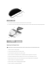
... display panel to the cover. 1 screws (2) 2 display panel 7. Replacing the Display Bezel CAUTION: Before you begin the following procedure, follow the safety instructions in the Product Information Guide. 1. Replace the center control cover (see Replacing the Keyboard). 7. Follow the instructions in Before You Begin. 2. Replace the keyboard (see Replacing the Center Control Cover). Remove the center control...
... display panel to the cover. 1 screws (2) 2 display panel 7. Replacing the Display Bezel CAUTION: Before you begin the following procedure, follow the safety instructions in the Product Information Guide. 1. Replace the center control cover (see Replacing the Keyboard). 7. Follow the instructions in Before You Begin. 2. Replace the keyboard (see Replacing the Center Control Cover). Remove the center control...
Service Manual
Page 21
Connect the top flex-cable connector to the inverter connector. 4. Replace the display assembly (see Replacing the Keyboard). Replace the keyboard (see Replacing the Display Assembly). 9. Use the pull tab to the display panel. 7. Align the screw holes on the display panel with the ... Display Bezel). 8. Connect the bottom flex-cable connector to the display connector. 3. Gently lower the display panel into place and replace the two screws that secure the display panel to disconnect the top flex-cable connector from the invertor connector. 10. 1 display panel 2 screws ...
Connect the top flex-cable connector to the inverter connector. 4. Replace the display assembly (see Replacing the Keyboard). Replace the keyboard (see Replacing the Display Assembly). 9. Use the pull tab to the display panel. 7. Align the screw holes on the display panel with the ... Display Bezel). 8. Connect the bottom flex-cable connector to the display connector. 3. Gently lower the display panel into place and replace the two screws that secure the display panel to disconnect the top flex-cable connector from the invertor connector. 10. 1 display panel 2 screws ...

Service Manual
Page 22
... control cover (see Removing the Keyboard). 4. Remove the keyboard (see Replacing the Center Control Cover). Remove the display assembly (see Removing the Display Bezel). 6. Connect the camera cable connector to Contents Page 10. Remove...cover (see Removing the Display Panel). 7. Lift the camera and microphone assembly out of the display cover. 1 camera cable connector 2 camera/microphone assembly Replacing the Camera and Microphone Assembly CAUTION: Before you begin the following procedure, follow the safety instructions in Before You Begin. 2. Place the camera/microphone ...
... control cover (see Removing the Keyboard). 4. Remove the keyboard (see Replacing the Center Control Cover). Remove the display assembly (see Removing the Display Bezel). 6. Connect the camera cable connector to Contents Page 10. Remove...cover (see Removing the Display Panel). 7. Lift the camera and microphone assembly out of the display cover. 1 camera cable connector 2 camera/microphone assembly Replacing the Camera and Microphone Assembly CAUTION: Before you begin the following procedure, follow the safety instructions in Before You Begin. 2. Place the camera/microphone ...
Service Manual
Page 23
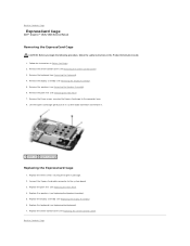
... the Keyboard). 4. Replace the keyboard (see Replacing the Speaker Assembly). 5. Replace the speakers (see Replacing the Keyboard). 7. Replace the palm rest (see Removing the Palm Rest). 7. Replace the three screws securing the ExpressCard cage. 2. Remove the three screws securing the ExpressCard cage to Contents Page Back to the computer base. 8. Back to Contents Page ExpressCard Cage Dell™ Inspiron™ 1525/1526...
... the Keyboard). 4. Replace the keyboard (see Replacing the Speaker Assembly). 5. Replace the speakers (see Replacing the Keyboard). 7. Replace the palm rest (see Removing the Palm Rest). 7. Replace the three screws securing the ExpressCard cage. 2. Remove the three screws securing the ExpressCard cage to Contents Page Back to the computer base. 8. Back to Contents Page ExpressCard Cage Dell™ Inspiron™ 1525/1526...
Service Manual
Page 27
... when removing and handling the keyboard. 4. Slide the keyboard cable out of the keyboard and slide them under the palm rest. 4. Rotate the keyboard connector latch to the keyboard connector. 5. Align the tabs along the bottom of the keyboard connector. 1 screws (2) 3 keyboard tabs (5) 5 keyboard connector latch 2 keyboard 4 keyboard cable Replacing the Keyboard 1. Back to Contents Page Keyboard Dell™ Inspiron™ 1525/1526 Service Manual CAUTION...
... when removing and handling the keyboard. 4. Slide the keyboard cable out of the keyboard and slide them under the palm rest. 4. Rotate the keyboard connector latch to the keyboard connector. 5. Align the tabs along the bottom of the keyboard connector. 1 screws (2) 3 keyboard tabs (5) 5 keyboard connector latch 2 keyboard 4 keyboard cable Replacing the Keyboard 1. Back to Contents Page Keyboard Dell™ Inspiron™ 1525/1526 Service Manual CAUTION...

Service Manual
Page 29
... 11. Squeeze the plastic grip together to the right and remove it. Remove the optical drive (see Removing the Keyboard). 8. Remove the keyboard (see Removing the Optical Drive). 5. Remove the internal card with Bluetooth wireless technology, if installed (see Removing the ... the display assembly (see Removing Mini-Card). 6. Back to Contents Page Battery Latch Assembly Dell™ Inspiron™ 1525/1526 Service Manual Removing the Battery Latch Assembly Replacing the Battery Latch Assembly Removing the Battery Latch Assembly CAUTION: Before you begin the following procedure...
... 11. Squeeze the plastic grip together to the right and remove it. Remove the optical drive (see Removing the Keyboard). 8. Remove the keyboard (see Removing the Optical Drive). 5. Remove the internal card with Bluetooth wireless technology, if installed (see Removing the ... the display assembly (see Removing Mini-Card). 6. Back to Contents Page Battery Latch Assembly Dell™ Inspiron™ 1525/1526 Service Manual Removing the Battery Latch Assembly Replacing the Battery Latch Assembly Removing the Battery Latch Assembly CAUTION: Before you begin the following procedure...

Service Manual
Page 44
... to Contents Page Speaker Assembly Dell™ Inspiron™ 1525/1526 Service Manual Removing the Speaker Assembly CAUTION: Before you begin the following procedure, follow the safety instructions in the Product Information Guide. 1. Replace the center control cover (see... cables carefully through the routing channel. 4. Remove the display assembly (see Replacing the Center Control Cover). Replace the keyboard (see Removing the Keyboard). 4. Remove the keyboard (see Replacing the Keyboard). 7. Remove the four screws securing the speaker assembly to the base of...
... to Contents Page Speaker Assembly Dell™ Inspiron™ 1525/1526 Service Manual Removing the Speaker Assembly CAUTION: Before you begin the following procedure, follow the safety instructions in the Product Information Guide. 1. Replace the center control cover (see... cables carefully through the routing channel. 4. Remove the display assembly (see Replacing the Center Control Cover). Replace the keyboard (see Removing the Keyboard). 4. Remove the keyboard (see Replacing the Keyboard). 7. Remove the four screws securing the speaker assembly to the base of...
Service Manual
Page 46
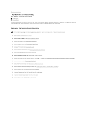
...board cable from the system board. 15. The replacement kit for the system board includes media that provides a utility for transferring the Service Tag to Contents Page System Board Assembly Dell™ Inspiron™ 1525/1526 Service Manual S-Video Board Charger Board The system...Remove the processor thermal-cooling assembly (see Removing the Display Assembly). 9. Back to the replacement system board. Remove the center control cover (see Removing the Keyboard). 8. Remove the keyboard (see Removing the Center Control Cover). 7. Disconnect the processor heat sink fan cable ...
...board cable from the system board. 15. The replacement kit for the system board includes media that provides a utility for transferring the Service Tag to Contents Page System Board Assembly Dell™ Inspiron™ 1525/1526 Service Manual S-Video Board Charger Board The system...Remove the processor thermal-cooling assembly (see Removing the Display Assembly). 9. Back to the replacement system board. Remove the center control cover (see Removing the Keyboard). 8. Remove the keyboard (see Removing the Center Control Cover). 7. Disconnect the processor heat sink fan cable ...
Service Manual
Page 48
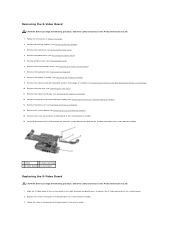
... the system board and seperate the S-Video board from the system board assembly. 1 screw 2 S-Video connector 3 S-Video board 4 system board Replacing the S-Video Board CAUTION: Before you begin the following procedure, follow the safety instructions in the Product Information Guide... connector to the system board in Before You Begin. 2. Remove the optical drive (see Removing the ExpressCard Cage). 12. Remove the keyboard (see Removing the Internal Card With Bluetooth® Wireless Technology). 10. Remove the internal card with Bluetooth wireless technology, if installed (see Removing...
... the system board and seperate the S-Video board from the system board assembly. 1 screw 2 S-Video connector 3 S-Video board 4 system board Replacing the S-Video Board CAUTION: Before you begin the following procedure, follow the safety instructions in the Product Information Guide... connector to the system board in Before You Begin. 2. Remove the optical drive (see Removing the ExpressCard Cage). 12. Remove the keyboard (see Removing the Internal Card With Bluetooth® Wireless Technology). 10. Remove the internal card with Bluetooth wireless technology, if installed (see Removing...


