User Guide
Page 1
DMC-1000 Chassis-Based Media Converter User's Guide Rev. 01 (Jan. 2002) 6012-9600131 (1907MCR11616000) Printed In Taiwan RECYCLABLE i
DMC-1000 Chassis-Based Media Converter User's Guide Rev. 01 (Jan. 2002) 6012-9600131 (1907MCR11616000) Printed In Taiwan RECYCLABLE i
User Guide
Page 2
Installing Media Converter 9 . Installing and Removing the Power Supply 11 UNDERSTANDING LED INDICATORS 12 FRONT PANEL 12 POWER AND FAN LED 12 TECHNICAL SPECIFICATIONS 13 ii TABLE OF CONTENTS TABLE OF CONTENTS II PREFACE 3 19" MEDIA CONVERTER CHASSIS SYSTEM 4 PRODUCT FEATURES 5 PRODUCT FEATURES 5 UNPACKING AND INSTALLATION 6 UNPACKING 6 INSTALLATION 6 DECIDING HOW TO INSTALL THE SYSTEM 7 . Connecting to 19-inch standard rack 8 . Mounted to Power (Power Supply 10 .
Installing Media Converter 9 . Installing and Removing the Power Supply 11 UNDERSTANDING LED INDICATORS 12 FRONT PANEL 12 POWER AND FAN LED 12 TECHNICAL SPECIFICATIONS 13 ii TABLE OF CONTENTS TABLE OF CONTENTS II PREFACE 3 19" MEDIA CONVERTER CHASSIS SYSTEM 4 PRODUCT FEATURES 5 PRODUCT FEATURES 5 UNPACKING AND INSTALLATION 6 UNPACKING 6 INSTALLATION 6 DECIDING HOW TO INSTALL THE SYSTEM 7 . Connecting to 19-inch standard rack 8 . Mounted to Power (Power Supply 10 .
User Guide
Page 3
...-FX (multi-mode ↔ single-mode) 1000BASE-T ↔ 1000BASE-SX/LX 1000BASE-SX ↔ 1000BASE-LX (multi-mode ↔ single-mode) In this manual is fitted with redundant power supplies. The system introduced here is capable of this manual, you will find: • Introduction on the Chassis System • Product features • Illustrative LEDs functions • Installation instructions • Specifications •...
...-FX (multi-mode ↔ single-mode) 1000BASE-T ↔ 1000BASE-SX/LX 1000BASE-SX ↔ 1000BASE-LX (multi-mode ↔ single-mode) In this manual is fitted with redundant power supplies. The system introduced here is capable of this manual, you will find: • Introduction on the Chassis System • Product features • Illustrative LEDs functions • Installation instructions • Specifications •...
User Guide
Page 4
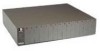
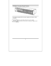
19" Media Converter Chassis System The chassis equipped with two power supplies and sixteen media converters AttentionPT!rhoeprciehtaasrsyismseydstieamcosnhviperstewristhanodnlaysoencoenpdowpoewr seurpspulpyp.ly are not included! 4
19" Media Converter Chassis System The chassis equipped with two power supplies and sixteen media converters AttentionPT!rhoeprciehtaasrsyismseydstieamcosnhviperstewristhanodnlaysoencoenpdowpoewr seurpspulpyp.ly are not included! 4
User Guide
Page 5
...190; The following items are designed to be hot swappable to allow easy and quick replacement: - PRODUCT FEATURES This chapter describes the features of taking over immediately ¾ The Media Converter's power isolation ensures each bay is electrically isolated from each other 5 Product Features &#...190; Plug-and-Play ¾ House up to Sixteen media converters ¾ Front panel LEDs for load-sharing purpose. &#...
...190; The following items are designed to be hot swappable to allow easy and quick replacement: - PRODUCT FEATURES This chapter describes the features of taking over immediately ¾ The Media Converter's power isolation ensures each bay is electrically isolated from each other 5 Product Features &#...190; Plug-and-Play ¾ House up to Sixteen media converters ¾ Front panel LEDs for load-sharing purpose. &#...
User Guide
Page 6
... chapter provides unpacking and installation information for replacement. Unpacking When unpacking the product package, you should place the equipment where it will not be between 32 and 104 6 When installing, take the following requirements: - Specifically, the site you place the ...contact your consideration: As with any electric device, you shall find these items listed below. ¾ 19" Media Converter Chassis System ¾ One power supply installed on the chassis ¾ One AC power cord ¾ User's Manual ¾ Accessories: rackmount screws (8 pcs) & rackmount ears (2 pcs)...
... chapter provides unpacking and installation information for replacement. Unpacking When unpacking the product package, you should place the equipment where it will not be between 32 and 104 6 When installing, take the following requirements: - Specifically, the site you place the ...contact your consideration: As with any electric device, you shall find these items listed below. ¾ 19" Media Converter Chassis System ¾ One power supply installed on the chassis ¾ One AC power cord ¾ User's Manual ¾ Accessories: rackmount screws (8 pcs) & rackmount ears (2 pcs)...

User Guide
Page 7
degrees Fahrenheit (0 to install media converters into the chassis with ease. Deciding How to Install the System We strongly suggest that the equipment receives adequate ventilation at the rear. Surrounding electrical devices should not exceed the electromagnetic field (RFC) standards for you install the chassis first, as this is more convenient for IEC... exhaust holes on the rear of the chassis. The accessories supplied in the following ways: 7 The relative humidity should be installed in the product package includes: rackmount screws(8 pcs) and rackmount brackets(2 pcs).
degrees Fahrenheit (0 to install media converters into the chassis with ease. Deciding How to Install the System We strongly suggest that the equipment receives adequate ventilation at the rear. Surrounding electrical devices should not exceed the electromagnetic field (RFC) standards for you install the chassis first, as this is more convenient for IEC... exhaust holes on the rear of the chassis. The accessories supplied in the following ways: 7 The relative humidity should be installed in the product package includes: rackmount screws(8 pcs) and rackmount brackets(2 pcs).
User Guide
Page 8
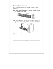
Apply four screws to each side of the chassis. Step 3: Proceed to the "Connecting to secure the chassis with the rack. Align the brackets to the side holes on the rack and use rack screws to Power" section. 8 Step 1: Attach the brackets to install the chassis into the rack. .Mounted to 19-inch standard rack Use the rackmount brackets and screws to each side and secure them tightly. Step 2: Carefully position the chassis into any EIA 19" standard rack.
Apply four screws to each side of the chassis. Step 3: Proceed to the "Connecting to secure the chassis with the rack. Align the brackets to the side holes on the rack and use rack screws to Power" section. 8 Step 1: Attach the brackets to install the chassis into the rack. .Mounted to 19-inch standard rack Use the rackmount brackets and screws to each side and secure them tightly. Step 2: Carefully position the chassis into any EIA 19" standard rack.

User Guide
Page 9
.... Unscrew the hand screw counter clockwise by using hand or screwdriver and pull the media converter module out on the carrier Step 3: Carefully slide in the module and fasten the hand screw clockwise by using hand or screwdriver. 9 Step 1: To install a media converter module onto the chassis, you have to unscrew the bay cover from the desired bay...
.... Unscrew the hand screw counter clockwise by using hand or screwdriver and pull the media converter module out on the carrier Step 3: Carefully slide in the module and fasten the hand screw clockwise by using hand or screwdriver. 9 Step 1: To install a media converter module onto the chassis, you have to unscrew the bay cover from the desired bay...
User Guide
Page 10
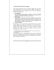
...is based on and share the current load. There is at your investment in place. 10 The chassis system is equipped with one power supply and allows one power supply, and a second power supply option is an optional solution for redundancy. .Connecting to...converter bay comes from any problem that you run the chassis system with two power supplies, you may remove any loss. During operation, both power supplies are in media converters. In case that it can have the following advanced performance. ♦ Hot Swappable - Each bay is equipped with two power supplies are switched...
...is based on and share the current load. There is at your investment in place. 10 The chassis system is equipped with one power supply and allows one power supply, and a second power supply option is an optional solution for redundancy. .Connecting to...converter bay comes from any problem that you run the chassis system with two power supplies, you may remove any loss. During operation, both power supplies are in media converters. In case that it can have the following advanced performance. ♦ Hot Swappable - Each bay is equipped with two power supplies are switched...
User Guide
Page 11
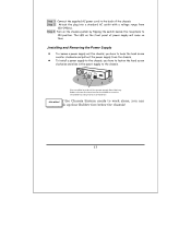
... supply out the chassis, you have to fasten the hand screw clockwise and slide in a nd o ut the p ower sup p ly from 100~240Vac. z To install a power supply to the chassis, you have to loose the hand screw counter clockwise and pull out the power supply from the chassis. You c a n slid... ON position. If the Chassis System needs to the back of power supply will come on the chassis system by flipping the switch beside the receptacle to the chassis. Step 1: Connect the supplied AC power cord to work alone, you can stick up four Rubber foot below the chassis! 11 Step 2: Attach...
... supply out the chassis, you have to fasten the hand screw clockwise and slide in a nd o ut the p ower sup p ly from 100~240Vac. z To install a power supply to the chassis, you have to loose the hand screw counter clockwise and pull out the power supply from the chassis. You c a n slid... ON position. If the Chassis System needs to the back of power supply will come on the chassis system by flipping the switch beside the receptacle to the chassis. Step 1: Connect the supplied AC power cord to work alone, you can stick up four Rubber foot below the chassis! 11 Step 2: Attach...
User Guide
Page 12
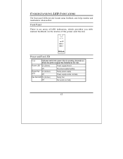
... On (Amber) Faulty Fan Off Fan works normally 12 UNDERSTANDING LED INDICATORS The front panel LEDs provide instant status feedback, and, helps monitor and troubleshoot when needed. DMC- 1000 Power and Fan LED 1 / 2 Indicates which provides you with instant feedback on the status of LED indicators, which the power (fan) is working, depends...
... On (Amber) Faulty Fan Off Fan works normally 12 UNDERSTANDING LED INDICATORS The front panel LEDs provide instant status feedback, and, helps monitor and troubleshoot when needed. DMC- 1000 Power and Fan LED 1 / 2 Indicates which provides you with instant feedback on the status of LED indicators, which the power (fan) is working, depends...
User Guide
Page 13
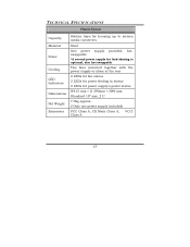
TECHNICAL SPECIFICATIONS Chassis System Capacity Material Power Cooling LED Indicators Dimensions Net Weight Emissions Sixteen bays for housing up to sixteen media converters Steel One power supply provided, hotswappable *A second power supply for load-sharing is optional, also hot-swappable Two fans mounted together with the power supply ...
TECHNICAL SPECIFICATIONS Chassis System Capacity Material Power Cooling LED Indicators Dimensions Net Weight Emissions Sixteen bays for housing up to sixteen media converters Steel One power supply provided, hotswappable *A second power supply for load-sharing is optional, also hot-swappable Two fans mounted together with the power supply ...
