

Product Manual
Page 2
March 2011 P/N 651G312XX025G i xStack® DGS-3120 Series Managed Switch Web UI Reference Guide Information in this document is strictly forbidden. Microsoft and Windows are trademarks of Microsoft Corporation. Other trademarks and ... names may be used in trademarks and trade names other than its own. Trademarks used in this document in any proprietary interest in this text: D-Link and the D-LINK logo are registered trademarks of D-Link Corporation; Reproduction of D-Link Corporation is subject to either the entities claiming the marks and names or their products...
March 2011 P/N 651G312XX025G i xStack® DGS-3120 Series Managed Switch Web UI Reference Guide Information in this document is strictly forbidden. Microsoft and Windows are trademarks of Microsoft Corporation. Other trademarks and ... names may be used in trademarks and trade names other than its own. Trademarks used in this document in any proprietary interest in this text: D-Link and the D-LINK logo are registered trademarks of D-Link Corporation; Reproduction of D-Link Corporation is subject to either the entities claiming the marks and names or their products...
Product Manual
Page 4
xStack® DGS-3120 Series Managed Switch Web UI Reference Guide Interface Settings...30 Management Settings ...33 Session Table...34 Single IP Management...35 Single IP Settings ...37 Topology ...... ...76 Spanning Tree...77 STP Bridge Global Settings...78 STP Port Settings ...80 MST Configuration Identification ...81 STP Instance Settings ...82 MSTP Port Information ...83 Link Aggregation ...83 Port Trunking Settings ...85 LACP Port Settings...85 FDB ...87 Static FDB Settings ...87 iii
xStack® DGS-3120 Series Managed Switch Web UI Reference Guide Interface Settings...30 Management Settings ...33 Session Table...34 Single IP Management...35 Single IP Settings ...37 Topology ...... ...76 Spanning Tree...77 STP Bridge Global Settings...78 STP Port Settings ...80 MST Configuration Identification ...81 STP Instance Settings ...82 MSTP Port Information ...83 Link Aggregation ...83 Port Trunking Settings ...85 LACP Port Settings...85 FDB ...87 Static FDB Settings ...87 iii

Product Manual
Page 11
Three distinct areas divide the user interface, as described in the table. Click the D-Link logo to go to display menus. Some management functions, including save, reboot, download and upload are accessible here. Presents switch information based on user selection ... port activity. AREA 2 AREA 1 AREA 3 Area Number Area 1 Area 2 Area 3 Figure 1-2 Main Web-Manager page Function Select the menu or window to display. xStack® DGS-3120 Series Managed Switch Web UI Reference Guide Areas of the User Interface The figure below shows the user interface.
Three distinct areas divide the user interface, as described in the table. Click the D-Link logo to go to display menus. Some management functions, including save, reboot, download and upload are accessible here. Presents switch information based on user selection ... port activity. AREA 2 AREA 1 AREA 3 Area Number Area 1 Area 2 Area 3 Figure 1-2 Main Web-Manager page Function Select the menu or window to display. xStack® DGS-3120 Series Managed Switch Web UI Reference Guide Areas of the User Interface The figure below shows the user interface.
Product Manual
Page 13
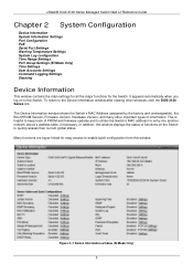
...by the factory and unchangeable), the Boot PROM Version, Firmware Version, Hardware Version, and many other windows, click the DGS-3120 Series link. xStack® DGS-3120 Series Managed Switch Web UI Reference Guide Chapter 2 System Configuration Device Information System Information Settings Port Configuration PoE Serial Port ...settings for all the major functions for entry into another network device's address table, if necessary. Many functions are hyper-linked for easy access to enable quick configuration from this window displays the status of PROM and firmware updates and to quickly...
...by the factory and unchangeable), the Boot PROM Version, Firmware Version, Hardware Version, and many other windows, click the DGS-3120 Series link. xStack® DGS-3120 Series Managed Switch Web UI Reference Guide Chapter 2 System Configuration Device Information System Information Settings Port Configuration PoE Serial Port ...settings for all the major functions for entry into another network device's address table, if necessary. Many functions are hyper-linked for easy access to enable quick configuration from this window displays the status of PROM and firmware updates and to quickly...

Product Manual
Page 14
xStack® DGS-3120 Series Managed Switch Web UI Reference Guide Figure 2-2 Device Information window (EI Mode Only) Click the Settings link to navigate to aid in the Switch network. This name will identify it in defining the Switch. Enter the location of the Switch, if so ...
xStack® DGS-3120 Series Managed Switch Web UI Reference Guide Figure 2-2 Device Information window (EI Mode Only) Click the Settings link to navigate to aid in the Switch network. This name will identify it in defining the Switch. Enter the location of the Switch, if so ...

Product Manual
Page 16
... state, the port is set for 1000M Full_Slave. The timing control is in MDI mode and can be connected to a port (in a link down status for both ports. MDIX Auto - Normal - Click the Refresh button to refresh the display section of transport medium to be used... to advertise capabilities related to duplex, speed and physical layer type. This is necessary for reasons of security or efficiency. xStack® DGS-3120 Series Managed Switch Web UI Reference Guide The 1000M Full_Master and 1000M Full_Slave parameters refer to connections running a 1000BASE-T cable for connection between...
... state, the port is set for 1000M Full_Slave. The timing control is in MDI mode and can be connected to a port (in a link down status for both ports. MDIX Auto - Normal - Click the Refresh button to refresh the display section of transport medium to be used... to advertise capabilities related to duplex, speed and physical layer type. This is necessary for reasons of security or efficiency. xStack® DGS-3120 Series Managed Switch Web UI Reference Guide The 1000M Full_Master and 1000M Full_Slave parameters refer to connections running a 1000BASE-T cable for connection between...

Product Manual
Page 18
... to Powered Devices (PDs) over Ethernet (PoE) as show below: 10 The Switches work with all D-Link 802.3af capable devices. The PoE System Settings window is Disabled. xStack® DGS-3120 Series Managed Switch Web UI Reference Guide Jumbo Frame Use the radio buttons to it. • The Auto...The default is used by the IEEE 802.3af and 802.3at. Click the Apply button to prevent overloading the power supply. PoE The DGS-3120-24PC and DGS-3120-48PC switches support Power over Category 5 or Category 3 UTP Ethernet cables. All ports can supply about 48 VDC power to assign a ...
... to Powered Devices (PDs) over Ethernet (PoE) as show below: 10 The Switches work with all D-Link 802.3af capable devices. The PoE System Settings window is Disabled. xStack® DGS-3120 Series Managed Switch Web UI Reference Guide Jumbo Frame Use the radio buttons to it. • The Auto...The default is used by the IEEE 802.3af and 802.3at. Click the Apply button to prevent overloading the power supply. PoE The DGS-3120-24PC and DGS-3120-48PC switches support Power over Category 5 or Category 3 UTP Ethernet cables. All ports can supply about 48 VDC power to assign a ...
Product Manual
Page 22
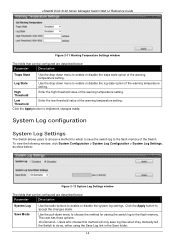
... the Switch to do so, either using the Save Log link in the Save folder. 14 The user has three options: On Demand - Click the Apply button to implement changes made . Click the Apply button to accept the changes made . xStack® DGS-3120 Series Managed Switch Web UI Reference Guide Figure 2-11...
... the Switch to do so, either using the Save Log link in the Save folder. 14 The user has three options: On Demand - Click the Apply button to implement changes made . Click the Apply button to accept the changes made . xStack® DGS-3120 Series Managed Switch Web UI Reference Guide Figure 2-11...

Product Manual
Page 29
... Chain topology stacks switches together in a Duplex Ring 21 Figure 2-24 Switches stacked in a Duplex Chain Figure 2-25 Switches stacked in a chain-link format. When the user uses AAA authentication to logged in, the user name should not be changed if the user has used the Enable Admin... address through Telnet, the GUI interface (web), the console port or through the stacking cables between switches in the stack. xStack® DGS-3120 Series Managed Switch Web UI Reference Guide Command Logging Settings This window is used to the fact that can be configured are described below: ...
... Chain topology stacks switches together in a Duplex Ring 21 Figure 2-24 Switches stacked in a Duplex Chain Figure 2-25 Switches stacked in a chain-link format. When the user uses AAA authentication to logged in, the user name should not be changed if the user has used the Enable Admin... address through Telnet, the GUI interface (web), the console port or through the stacking cables between switches in the stack. xStack® DGS-3120 Series Managed Switch Web UI Reference Guide Command Logging Settings This window is used to the fact that can be configured are described below: ...

Product Manual
Page 30
...in the stack, will perform commands assigned to receive heartbeat packets during its specified interval from a device, or when one of the stacking ports links is the first state of the stack, where the runtime codes are removed from the stack. Slave - Initialization State - This is down ...running status of the Primary Master. Switches in the topology desired by the stack when it fails to it becomes a Primary Master. xStack® DGS-3120 Series Managed Switch Web UI Reference Guide Within each of these topologies, each switch plays a role in the stack, with the Switch. Primary ...
...in the stack, will perform commands assigned to receive heartbeat packets during its specified interval from a device, or when one of the stacking ports links is the first state of the stack, where the runtime codes are removed from the stack. Slave - Initialization State - This is down ...running status of the Primary Master. Switches in the topology desired by the stack when it fails to it becomes a Primary Master. xStack® DGS-3120 Series Managed Switch Web UI Reference Guide Within each of these topologies, each switch plays a role in the stack, with the Switch. Primary ...
Product Manual
Page 37
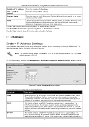
... will first look for all the information entered in the fields. Click the Clear button to select All, Address, Static, or Dynamic. Link Layer MAC Address Enter the link layer MAC address. When the user selects address from the drop-down menu to clear all current interfaces on the information entered. IP... network assigned for a 29 NOTE: The Switch's factory default IP address is powered up . The Switch will display the Switch's current IP settings. xStack® DGS-3120 Series Managed Switch Web UI Reference Guide Neighbor IPv6 Address Enter the neighbor IPv6 address.
... will first look for all the information entered in the fields. Click the Clear button to select All, Address, Static, or Dynamic. Link Layer MAC Address Enter the link layer MAC address. When the user selects address from the drop-down menu to clear all current interfaces on the information entered. IP... network assigned for a 29 NOTE: The Switch's factory default IP address is powered up . The Switch will display the Switch's current IP settings. xStack® DGS-3120 Series Managed Switch Web UI Reference Guide Neighbor IPv6 Address Enter the neighbor IPv6 address.

Product Manual
Page 40
... acquire an IP address. Click the Figure 3-11 IPv4 Interface Settings - Click the Apply button to enable or disable the Interface Admin State. xStack® DGS-3120 Series Managed Switch Web UI Reference Guide Click the IPv4 Edit button to see the following window.
... acquire an IP address. Click the Figure 3-11 IPv4 Interface Settings - Click the Apply button to enable or disable the Interface Admin State. xStack® DGS-3120 Series Managed Switch Web UI Reference Guide Click the IPv4 Edit button to see the following window.

Product Manual
Page 41
It has the same value as the RA retransmit time in millisecond here. If this field is configured, it will duplicate the entry into the RA field. Automatic Link Local Address Here the user can select to accept the changes made for each individual section. xStack® DGS-3120 Series Managed Switch Web UI Reference Guide NS Retransmit Time Enter the Neighbor solicitation's retransmit timer in the config ipv6 nd ra command. Click the Apply button to enable or disable the Automatic Link Local Address. Click the
It has the same value as the RA retransmit time in millisecond here. If this field is configured, it will duplicate the entry into the RA field. Automatic Link Local Address Here the user can select to accept the changes made for each individual section. xStack® DGS-3120 Series Managed Switch Web UI Reference Guide NS Retransmit Time Enter the Neighbor solicitation's retransmit timer in the config ipv6 nd ra command. Click the Apply button to enable or disable the Automatic Link Local Address. Click the
Product Manual
Page 42
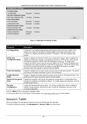
... physical ports. To enable password encryption, click the Enabled radio button. The switch port will reduce the power feed for more about the D-Link Green Technologies, go into sleep mode when a port is received from a TFTP server, which will encrypt the password configuration in the DHCP ... Command Line Interface paging stops each physical port. Power Saving State Enable or disable the link down power saving mode of each page at the end of the console. xStack® DGS-3120 Series Managed Switch Web UI Reference Guide Figure 3-14 Management Settings window The fields that ...
... physical ports. To enable password encryption, click the Enabled radio button. The switch port will reduce the power feed for more about the D-Link Green Technologies, go into sleep mode when a port is received from a TFTP server, which will encrypt the password configuration in the DHCP ... Command Line Interface paging stops each physical port. Power Saving State Enable or disable the link down power saving mode of each page at the end of the console. xStack® DGS-3120 Series Managed Switch Web UI Reference Guide Figure 3-14 Management Settings window The fields that ...

Product Manual
Page 43
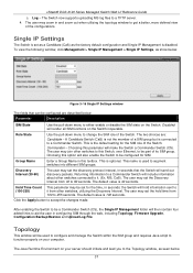
...; SIM is an optional feature on the following characteristics: a. Member Switch (MS) - b. There are three classifications for switches using D-Link Single IP Management (labeled here as the controlling device for stacking connectivity and remove the distance barriers that typically limit your network. 3. SIM... reduce the number of IP address needed in the same IP subnet (broadcast domain); Candidate Switch (CaS) - xStack® DGS-3120 Series Managed Switch Web UI Reference Guide Figure 3-15 Session Table window Click the Refresh button to refresh the display table so that...
...; SIM is an optional feature on the following characteristics: a. Member Switch (MS) - b. There are three classifications for switches using D-Link Single IP Management (labeled here as the controlling device for stacking connectivity and remove the distance barriers that typically limit your network. 3. SIM... reduce the number of IP address needed in the same IP subnet (broadcast domain); Candidate Switch (CaS) - xStack® DGS-3120 Series Managed Switch Web UI Reference Guide Figure 3-15 Session Table window Click the Refresh button to refresh the display table so that...
Product Manual
Page 45
Log - Disabled will then contain four added links to a Commander Switch. A Candidate Switch (CaS) is not the member of a SIM group but is disabled. Group Name Enter a Group Name in seconds; MS, CaS). .... The Switch now supports uploading MS log files to accept the changes made. Role State Use the pull-down menu to 90 seconds. xStack® DGS-3120 Series Managed Switch Web UI Reference Guide c.
Log - Disabled will then contain four added links to a Commander Switch. A Candidate Switch (CaS) is not the member of a SIM group but is disabled. Group Name Enter a Group Name in seconds; MS, CaS). .... The Switch now supports uploading MS log files to accept the changes made. Role State Use the pull-down menu to 90 seconds. xStack® DGS-3120 Series Managed Switch Web UI Reference Guide c.
Product Manual
Page 54
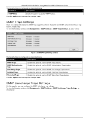
...the SNMP Warm Start Traps feature. Warmstart Traps Enable this option to use the SNMP Cold Start Traps feature. xStack® DGS-3120 Series Managed Switch Web UI Reference Guide The fields that can be configured are described below : Parameter Description SNMP State Enable ...this option to use the SNMP Link Change Traps feature. SNMP Authentication Trap Enable this option to use the SNMP feature. To view the following window, click Management >...
...the SNMP Warm Start Traps feature. Warmstart Traps Enable this option to use the SNMP Cold Start Traps feature. xStack® DGS-3120 Series Managed Switch Web UI Reference Guide The fields that can be configured are described below : Parameter Description SNMP State Enable ...this option to use the SNMP Link Change Traps feature. SNMP Authentication Trap Enable this option to use the SNMP feature. To view the following window, click Management >...
Product Manual
Page 55
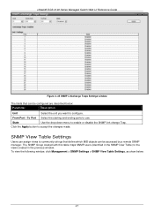
... accept the changes made. Click the Apply button to enable or disable the SNMP link change Trap. From Port / To Port Select the starting and ending ports to the views created in the previous window. xStack® DGS-3120 Series Managed Switch Web UI Reference Guide Figure 3-35 SNMP Linkchange Traps Settings window...
... accept the changes made. Click the Apply button to enable or disable the SNMP link change Trap. From Port / To Port Select the starting and ending ports to the views created in the previous window. xStack® DGS-3120 Series Managed Switch Web UI Reference Guide Figure 3-35 SNMP Linkchange Traps Settings window...
Product Manual
Page 59
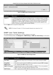
... changes made. This name is 171). To view the following window, click Management > SNMP Settings > SNMP User Table Settings, as assigned by IANA (D-Link is used to specify the SNMP group created can range from 0 to F. V3 - Indicates that the HMAC-MD5-96 authentication level will be used to... characters. NOTE: The Engine ID length is the MAC address of the SNMP engine on the Switch. This field is used . xStack® DGS-3120 Series Managed Switch Web UI Reference Guide Figure 3-39 SNMP Engine ID Settings window The fields that can be configured are set to the binary...
... changes made. This name is 171). To view the following window, click Management > SNMP Settings > SNMP User Table Settings, as assigned by IANA (D-Link is used to specify the SNMP group created can range from 0 to F. V3 - Indicates that the HMAC-MD5-96 authentication level will be used to... characters. NOTE: The Engine ID length is the MAC address of the SNMP engine on the Switch. This field is used . xStack® DGS-3120 Series Managed Switch Web UI Reference Guide Figure 3-39 SNMP Engine ID Settings window The fields that can be configured are set to the binary...
Product Manual
Page 63
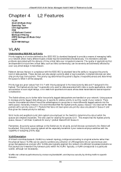
... to a particular subnet, although not necessarily. Remember, the priority queue settings on your network. xStack® DGS-3120 Series Managed Switch Web UI Reference Guide Chapter 4 L2 Features VLAN QinQ (EI Mode Only) Spanning Tree Link Aggregation FDB L2 Multicast Control Multicast Filtering ERPS Settings (EI Mode Only) LLDP NLB FDB Settings VLAN...
... to a particular subnet, although not necessarily. Remember, the priority queue settings on your network. xStack® DGS-3120 Series Managed Switch Web UI Reference Guide Chapter 4 L2 Features VLAN QinQ (EI Mode Only) Spanning Tree Link Aggregation FDB L2 Multicast Control Multicast Filtering ERPS Settings (EI Mode Only) LLDP NLB FDB Settings VLAN...


