Operation Manual
Page 1
Operator's Manual I x 42" Belt SANDER Model No. 351.215130 Sears, Roebuck and Co., Hoffman Estates, IL 60179 U.S.A. www.sears.com/craftsman 20067.01 Draft (11/07/03)
Operator's Manual I x 42" Belt SANDER Model No. 351.215130 Sears, Roebuck and Co., Hoffman Estates, IL 60179 U.S.A. www.sears.com/craftsman 20067.01 Draft (11/07/03)

Operation Manual
Page 2
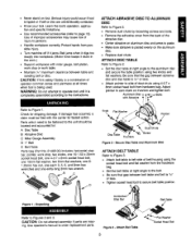
.... This warranty gives you specific legal rights and you are removed before operating tool. Do not use power tools in severe personal injury. Warrant.y SafetyRules Unpackin.g Assembly Installatio..n Operation Maintenanc..e Troubleshooti.n..g PartsIllustratioanndList EspaSc..l 2 2-3 3 3-4 4-5 5-8 8-9 10 12-13 14-22 FULL ONE YEAR WARRANTY If this product fails due to order replacement parts.) KNOW HOW TO USE TOOL • Use right tool for job. Do not perform makeshift repairs. (Use parts list provided...
.... This warranty gives you specific legal rights and you are removed before operating tool. Do not use power tools in severe personal injury. Warrant.y SafetyRules Unpackin.g Assembly Installatio..n Operation Maintenanc..e Troubleshooti.n..g PartsIllustratioanndList EspaSc..l 2 2-3 3 3-4 4-5 5-8 8-9 10 12-13 14-22 FULL ONE YEAR WARRANTY If this product fails due to order replacement parts.) KNOW HOW TO USE TOOL • Use right tool for job. Do not perform makeshift repairs. (Use parts list provided...
Operation Manual
Page 3
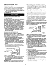
.... (Motor force keeps it is being used. Figure 1 - CAUTION; WARNING; Adjust pointer to order replacement parts. Use operator's manual to zero mark on tool. A -- .dc.--B C Knob FlatWasher .-" Pointer Disc'_able T_Jion _'X : Chute "_8_ "Screw Figure 2 - Unpacking Stop Bar Refer to page 13). Learn the tool's operation, application and specific limitations, • Use recommended accessories (refer to Figures 2 and 3. AluminumDisc withAbrasive Refer to operate tool until it stuck in the work.) • Support...
.... (Motor force keeps it is being used. Figure 1 - CAUTION; WARNING; Adjust pointer to order replacement parts. Use operator's manual to zero mark on tool. A -- .dc.--B C Knob FlatWasher .-" Pointer Disc'_able T_Jion _'X : Chute "_8_ "Screw Figure 2 - Unpacking Stop Bar Refer to page 13). Learn the tool's operation, application and specific limitations, • Use recommended accessories (refer to Figures 2 and 3. AluminumDisc withAbrasive Refer to operate tool until it stuck in the work.) • Support...
Operation Manual
Page 4
... rigid green tab or terminal on nameplate. • Power supply to protect operator from outlet. • Plug must be of the adapter must be grounded while in use to the motor is properly grounded. Remove the key to Figure 3, page 3. ner. If repair or replacement of the electric cord or plug is necessary, do not connect the green (or green and yellow) wire...
... rigid green tab or terminal on nameplate. • Power supply to protect operator from outlet. • Plug must be of the adapter must be grounded while in use to the motor is properly grounded. Remove the key to Figure 3, page 3. ner. If repair or replacement of the electric cord or plug is necessary, do not connect the green (or green and yellow) wire...
Operation Manual
Page 5
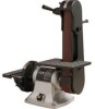
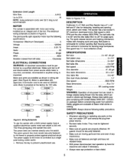
... operation by a single pole locking rocker switch. • Remove the key to 45 ° for contour sanding. They must remain securely fastened to the frame to Figures 7-15. The permanently split capacitor motor has the following safety precautions. Disc guard has 1'/2" dust collection chute. e 120V 2-Gra ( l-Black _ 240V Figure 6 -Wiring Schematic To use . The green ground line must be used at 120/240 volts. DESCRIPTION Craftsman 2 x 6" Belt and Disc Sander...
... operation by a single pole locking rocker switch. • Remove the key to 45 ° for contour sanding. They must remain securely fastened to the frame to Figures 7-15. The permanently split capacitor motor has the following safety precautions. Disc guard has 1'/2" dust collection chute. e 120V 2-Gra ( l-Black _ 240V Figure 6 -Wiring Schematic To use . The green ground line must be used at 120/240 volts. DESCRIPTION Craftsman 2 x 6" Belt and Disc Sander...
Operation Manual
Page 6
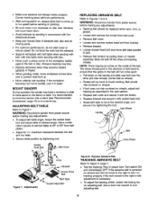
... slide or move to desired angle. ReplaceAbrasive Belt TRACKING ABRASIVE BELT Refer to turn adjusting bolt. 6 Use a 4mm hex wrench to Figure 9, page 7. • Test the tracking. BELT WARNING: Disconnect sander from power source before sanding or grinding. • Be sure motor runs clockwise on disc side. Idler Wheel Handle Figure 7 - Turn switch ON and immediately OFF. The arrow should point in the direction of abrasive belt, disc and all moving parts...
... slide or move to desired angle. ReplaceAbrasive Belt TRACKING ABRASIVE BELT Refer to turn adjusting bolt. 6 Use a 4mm hex wrench to Figure 9, page 7. • Test the tracking. BELT WARNING: Disconnect sander from power source before sanding or grinding. • Be sure motor runs clockwise on disc side. Idler Wheel Handle Figure 7 - Turn switch ON and immediately OFF. The arrow should point in the direction of abrasive belt, disc and all moving parts...
Operation Manual
Page 7
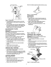
...; Replace belt cover and tighten knobs. WARNING: Disconnect sander from power source before making any adjustments. • The belt housing can be tilted to a horizontal position. • Remove the belt table by removing the socket head bolt and flat washer. • Loosen the housing lock bolt, tilt the belt housing to the horizontal position, and tighten the bolt to provide adequate support. Tighten locking nut to desired sharpening angle and tighten securely. Use belt sander to...
...; Replace belt cover and tighten knobs. WARNING: Disconnect sander from power source before making any adjustments. • The belt housing can be tilted to a horizontal position. • Remove the belt table by removing the socket head bolt and flat washer. • Loosen the housing lock bolt, tilt the belt housing to the horizontal position, and tighten the bolt to provide adequate support. Tighten locking nut to desired sharpening angle and tighten securely. Use belt sander to...
Operation Manual
Page 8
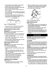
.... Disc table is adjustable from 0 to 45 ° to abrasive disc. • When disc table is frequently vacuumed free of the miter gauge. WARNING; Use soap and water to Figure 2. Remove belt table. • Mount work stop to sander using the socket head bolt and washers. • Use a combination square to adjust the work stop at desired angle, lock it into position by peeling it on wheels causing belt to slip. 8 ADJUSTING DISC TABLE ANGLE Refer to clean painted parts, rubber parts and plastic guards. minum disc...
.... Disc table is adjustable from 0 to 45 ° to abrasive disc. • When disc table is frequently vacuumed free of the miter gauge. WARNING; Use soap and water to Figure 2. Remove belt table. • Mount work stop to sander using the socket head bolt and washers. • Use a combination square to adjust the work stop at desired angle, lock it into position by peeling it on wheels causing belt to slip. 8 ADJUSTING DISC TABLE ANGLE Refer to clean painted parts, rubber parts and plastic guards. minum disc...

Operation Manual
Page 9
KEEP TOOL IN REPAIR • If power cord is available at your nearest Sears store. 9 Repair service is worn, cut, or damaged in any way, have it replaced immediately. • Replace worn abrasives when needed. • Replace any damaged or missing parts. Use parts list to repair motor may create a hazard unless repair is done by a qualified service technician. Any attempt to order parts.
KEEP TOOL IN REPAIR • If power cord is available at your nearest Sears store. 9 Repair service is worn, cut, or damaged in any way, have it replaced immediately. • Replace worn abrasives when needed. • Replace any damaged or missing parts. Use parts list to repair motor may create a hazard unless repair is done by a qualified service technician. Any attempt to order parts.
Operation Manual
Page 10
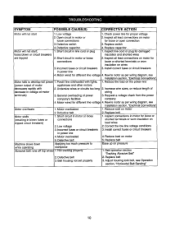
... much pressure to develop full power 1. Defective belt 3. Replace belt Ease up on lead wires 2. See operation section "Tracking Abrasive Belt" 2. SYMPTOM POSSIBLE CAUSE(S) CORRECTIVE ACTION Motor will not start 1. Check power line for damaged insulation and shorted wires 2. Rewire motor as per wiring diagram, see Installation section, "Electrical Connections" Motor overheats 1. General overloading of decrease in motor for loose or shorted terminals or worn insulation on motor 5. Low voltage 3. Replace switch...
... much pressure to develop full power 1. Defective belt 3. Replace belt Ease up on lead wires 2. See operation section "Tracking Abrasive Belt" 2. SYMPTOM POSSIBLE CAUSE(S) CORRECTIVE ACTION Motor will not start 1. Check power line for damaged insulation and shorted wires 2. Rewire motor as per wiring diagram, see Installation section, "Electrical Connections" Motor overheats 1. General overloading of decrease in motor for loose or shorted terminals or worn insulation on motor 5. Low voltage 3. Replace switch...
Operation Manual
Page 13
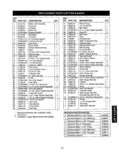
...Key 1 Base 1 #10-24 x 3/8" Flange Screw 5 Base Bumper 4 Base Cover 1 #10-24 x 1/4" Flange Screw 4 1/4" Lock Washer* 2 1/4"-20 Hex Nut* 2 Capacitor 16MFD 1 Disc Guard 1 Dust Collection Chute 1 Aluminum Disc 1 l-Abrasive Disc 1 6-1.0mm Hex Nut* 3 Knob 2 6mm Flat Washer* 6 Disc Table 1 1/4-20 x 1/4" Set Screw* 1 6-1.0 x 20mm Socket Head Bolt* 2 8mm Flat Washer* 1 8-1.25 x 30mm Socket Head Bolt* 1 Lower Belt Guard 1 4-0.7 x 8mm Socket Head Bolt* 2 10-1.5 x 25mm Socket Head Bolt 1 1Omm Flat Washer* 1 Work Stop 1 Stop Bracket 1 Drive Wheel 1 Belt...
...Key 1 Base 1 #10-24 x 3/8" Flange Screw 5 Base Bumper 4 Base Cover 1 #10-24 x 1/4" Flange Screw 4 1/4" Lock Washer* 2 1/4"-20 Hex Nut* 2 Capacitor 16MFD 1 Disc Guard 1 Dust Collection Chute 1 Aluminum Disc 1 l-Abrasive Disc 1 6-1.0mm Hex Nut* 3 Knob 2 6mm Flat Washer* 6 Disc Table 1 1/4-20 x 1/4" Set Screw* 1 6-1.0 x 20mm Socket Head Bolt* 2 8mm Flat Washer* 1 8-1.25 x 30mm Socket Head Bolt* 1 Lower Belt Guard 1 4-0.7 x 8mm Socket Head Bolt* 2 10-1.5 x 25mm Socket Head Bolt 1 1Omm Flat Washer* 1 Work Stop 1 Stop Bracket 1 Drive Wheel 1 Belt...

Operation Manual
Page 24
... matter who made it, no matter who sold itI For the replacement parts, accessories and owner's manuals that you need to do-it-yourself. For Sears professional installation of your home-of Sears, Roebuckand Co. and Canada) www.sears.com www.sears.ca Our Home For repair of carry-in your nearest Sears Parts & Repair Center. 1 800 488 1222 Call anytime, day or night (U.S.A. MCMarque de...
... matter who made it, no matter who sold itI For the replacement parts, accessories and owner's manuals that you need to do-it-yourself. For Sears professional installation of your home-of Sears, Roebuckand Co. and Canada) www.sears.com www.sears.ca Our Home For repair of carry-in your nearest Sears Parts & Repair Center. 1 800 488 1222 Call anytime, day or night (U.S.A. MCMarque de...


