
Operation Manual
Page 1
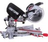
SLiDiNG COMPOUND MITER SAW WiTH LASER TRAC ® Model No. 137.212370 CAUTION: Before using this Miter Saw, read this manual and follow all its Safety Rules and Operating instructions • Safety Instructions • installation • Operation • Maintenance e Parts List Customer Help Line For Technical Support 1-800-843-1682 Sears Parts & Repair Center 1-800-488-1222 Sears, Roebuck and Co., Hoffman Estates, Visit our Craftsman website: www.sears.condcraftsman Part No. 137212370001 IL 60179 USA Operator's Manual CRSFrSMSN° 10 in.
SLiDiNG COMPOUND MITER SAW WiTH LASER TRAC ® Model No. 137.212370 CAUTION: Before using this Miter Saw, read this manual and follow all its Safety Rules and Operating instructions • Safety Instructions • installation • Operation • Maintenance e Parts List Customer Help Line For Technical Support 1-800-843-1682 Sears Parts & Repair Center 1-800-488-1222 Sears, Roebuck and Co., Hoffman Estates, Visit our Craftsman website: www.sears.condcraftsman Part No. 137212370001 IL 60179 USA Operator's Manual CRSFrSMSN° 10 in.
Operation Manual
Page 2
... date of Terms Assembly Adjustments Operat ion Maintenance Troubleshooting Guide Parts List PAGE 8 9 10 14 16 24 25 26 ONE-YEAR FULL WARRANTY ON CRAFTSMAN TOOL If this warranty will apply for Assembly 6 Carton Contents 7 SECTION Know Your Sliding Compound Miter Saw ..... MOTOR MITER SAW Power Source 120',/AC, 60Hz, 15 Amp Arbor Shaft Size 5/8 in . Speed...
... date of Terms Assembly Adjustments Operat ion Maintenance Troubleshooting Guide Parts List PAGE 8 9 10 14 16 24 25 26 ONE-YEAR FULL WARRANTY ON CRAFTSMAN TOOL If this warranty will apply for Assembly 6 Carton Contents 7 SECTION Know Your Sliding Compound Miter Saw ..... MOTOR MITER SAW Power Source 120',/AC, 60Hz, 15 Amp Arbor Shaft Size 5/8 in . Speed...
Operation Manual
Page 3
... shows the correct size to your health. The smaller the gauge number, the heavier the cord. 11. WEAR A FACE MASK OR DUST MASK, Sawing operation produces dust. 14. Check for alignment of moving parts, binding of moving parts. MAINTAIN TOOLS WITH CARE, Keep tools sharp and clean for ...recommended accessories. DIRECTION OF FEED. Always operate the saw in damp locations or expose them to a complete stop, and then unplug the unit. 21. DO NOT USE iN DANGEROUS ENVIRONMENTS. Do not...
... shows the correct size to your health. The smaller the gauge number, the heavier the cord. 11. WEAR A FACE MASK OR DUST MASK, Sawing operation produces dust. 14. Check for alignment of moving parts, binding of moving parts. MAINTAIN TOOLS WITH CARE, Keep tools sharp and clean for ...recommended accessories. DIRECTION OF FEED. Always operate the saw in damp locations or expose them to a complete stop, and then unplug the unit. 21. DO NOT USE iN DANGEROUS ENVIRONMENTS. Do not...
Operation Manual
Page 4
... and is clean before removing or securing the workpiece, changing the workpiece angle or changing the angle of the blade. 21. This miter saw is designed for operation at all handles are clean and the arbor bolt is running. 14. SHUT OFF the power before operation. Your...is a universal, nonreversible type. I 0 in one of the positive stops. NEVER use the miter saw is positioned in . MAKE SURE the work firmly against the fence and table. DISCONNECT the saw to the blade when the saw blade. ALLOW the motor to come to a 120 V circuit. MAKE SURE both the blade...
... and is clean before removing or securing the workpiece, changing the workpiece angle or changing the angle of the blade. 21. This miter saw is designed for operation at all handles are clean and the arbor bolt is running. 14. SHUT OFF the power before operation. Your...is a universal, nonreversible type. I 0 in one of the positive stops. NEVER use the miter saw is positioned in . MAKE SURE the work firmly against the fence and table. DISCONNECT the saw to the blade when the saw blade. ALLOW the motor to come to a 120 V circuit. MAKE SURE both the blade...
Operation Manual
Page 5
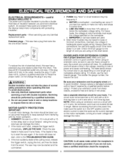
...and cause overheating. Servicing should be blown out or vacuumed frequently to carp/the current your product will fit in loss of electrical shock, this saw has a polarized plug (one hea W enough to keep sawdust from the internal metal motor components with double insulation. MOTOR SAFETY PROTECTION IMPORTANT: ... the cord. [A WARNINI G Double insulation does not take the place of Cord Not MoreThan 25ft. 50ft. 100ft. 150ft. 6 18 16 16 14 10 18 16 14 12 12 16 16 14 12 CAUTION: In all cases make too many start , release the trigger switch immediately. If the motor...
...and cause overheating. Servicing should be blown out or vacuumed frequently to carp/the current your product will fit in loss of electrical shock, this saw has a polarized plug (one hea W enough to keep sawdust from the internal metal motor components with double insulation. MOTOR SAFETY PROTECTION IMPORTANT: ... the cord. [A WARNINI G Double insulation does not take the place of Cord Not MoreThan 25ft. 50ft. 100ft. 150ft. 6 18 16 16 14 10 18 16 14 12 12 16 16 14 12 CAUTION: In all cases make too many start , release the trigger switch immediately. If the motor...
Operation Manual
Page 6
... avoid the risk of personal injury, do not modify this miter saw. ACCESSORIES Visit your CARBIDE TIPPED SAW BLADE. Ferrous metal cutting and the use of any cutting tool except 10 inch saw blade guard in place. Do not operate the saw without the proper saw blades which meet the requirements under recommended accessories is flipped over...
... avoid the risk of personal injury, do not modify this miter saw. ACCESSORIES Visit your CARBIDE TIPPED SAW BLADE. Ferrous metal cutting and the use of any cutting tool except 10 inch saw blade guard in place. Do not operate the saw without the proper saw blades which meet the requirements under recommended accessories is flipped over...
Operation Manual
Page 7
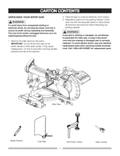
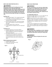
...not plug the power cord into a source of the machine. , Place the saw by the switch handle or miter table handle. It may cause misalignment. Miter Saw Blade Wrench Dust Bag Hold-Down Clamp Miter Handle UNPACKING YOUR MITER SAW [A WARNIN[ G To avoid injury from unexpected starting or electrical shock, do ...not attempt to make certain all parts from the packing material. Remove the miter saw , or plug in carrying handles located at the top of power during unpacking and assembly. Call 1-800-4-MY-HOME e for before...
...not plug the power cord into a source of the machine. , Place the saw by the switch handle or miter table handle. It may cause misalignment. Miter Saw Blade Wrench Dust Bag Hold-Down Clamp Miter Handle UNPACKING YOUR MITER SAW [A WARNIN[ G To avoid injury from unexpected starting or electrical shock, do ...not attempt to make certain all parts from the packing material. Remove the miter saw , or plug in carrying handles located at the top of power during unpacking and assembly. Call 1-800-4-MY-HOME e for before...
Operation Manual
Page 9
...raised position. BEVEL SCALE - STOP LATCH - SWITCH HANDLE - Misalignment of material removed by a spinning object in combination with the miter handle, it Pocksthe miter saw blade tips, bent outward in the lowered position for access to keep the blade from rotating while tightening or loosening the arbor ... of the workpiece that has hardened. Loosen this screw and rotate the plate for compact storage and transportation. Used to mount the miter saw in opposite directions to each other proper device to its upright position when the handle is mounted. BEVEL CUT -An angle cut...
...raised position. BEVEL SCALE - STOP LATCH - SWITCH HANDLE - Misalignment of material removed by a spinning object in combination with the miter handle, it Pocksthe miter saw blade tips, bent outward in the lowered position for access to keep the blade from rotating while tightening or loosening the arbor ... of the workpiece that has hardened. Loosen this screw and rotate the plate for compact storage and transportation. Used to mount the miter saw in opposite directions to each other proper device to its upright position when the handle is mounted. BEVEL CUT -An angle cut...
Operation Manual
Page 10
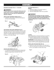
...1. IA WARNINGI To avoid injury and damage to the up position. Fig. Fig. B-1 3I 2 Locking When transporting or storing the miter saw , the slide carriage should always be locked in the down position. 1. Never use the stop latch knob (2) into the hole located at the front ...of the dust bag (1). 2. B SAW BLADE WRENCH (FIG. ALWAYS use . Estimated Assembly Time: 5 - 10 minutes [,AWAR"I"GI To avoid injury, do not connect this Operator's Manual. A CUTTING HEAD (FIG. When transporting or storing the miter saw , the cutting head should always be locked in ...
...1. IA WARNINGI To avoid injury and damage to the up position. Fig. Fig. B-1 3I 2 Locking When transporting or storing the miter saw , the slide carriage should always be locked in the down position. 1. Never use the stop latch knob (2) into the hole located at the front ...of the dust bag (1). 2. B SAW BLADE WRENCH (FIG. ALWAYS use . Estimated Assembly Time: 5 - 10 minutes [,AWAR"I"GI To avoid injury, do not connect this Operator's Manual. A CUTTING HEAD (FIG. When transporting or storing the miter saw , the cutting head should always be locked in ...
Operation Manual
Page 11
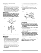
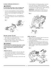
... prior to avoid accidental starting. To remove, loosen and remove the six screws (1) on a level work surface. = Bolt or clamp the saw to performing a cutting operation. • Do not start the sliding compound miter saw without checking for blade clearance by the switch handle. E-1 2 J_ \_._/2 2 REMOVING AND iNSTALLiNG THE TABLE INSERT (FIG. e Lock the...
... prior to avoid accidental starting. To remove, loosen and remove the six screws (1) on a level work surface. = Bolt or clamp the saw to performing a cutting operation. • Do not start the sliding compound miter saw without checking for blade clearance by the switch handle. E-1 2 J_ \_._/2 2 REMOVING AND iNSTALLiNG THE TABLE INSERT (FIG. e Lock the...
Operation Manual
Page 12
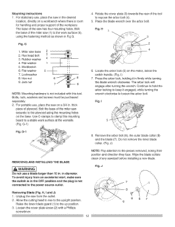
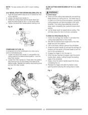
... to expose the arbor bolt (4). 5. J Removing Blade (Fig. Raise the lower blade guard (1) to the upright position. Bolt the base of the miter saw has four mounting holes. Use C-clamps to the work surface at the worksite. (Fig. Rotate the cover plate (3) towards the rear of the... to the plywood using the fastening method as shown in diameter. For stationary use a blade larger than 10 in the OFF position and the plug is room for handling and proper support of the miter saw on the motor, below the switch handle. (Fig. MHeitxer hseaawd bbaoslte 23 3. Flat washer 5 7. ...
... to expose the arbor bolt (4). 5. J Removing Blade (Fig. Raise the lower blade guard (1) to the upright position. Bolt the base of the miter saw has four mounting holes. Use C-clamps to the work surface at the worksite. (Fig. Rotate the cover plate (3) towards the rear of the... to the plywood using the fastening method as shown in diameter. For stationary use a blade larger than 10 in the OFF position and the plug is room for handling and proper support of the miter saw on the motor, below the switch handle. (Fig. MHeitxer hseaawd bbaoslte 23 3. Flat washer 5 7. ...
Operation Manual
Page 13
...the plug to access the cover plate screw. 6. Fig. Avoid direct eye contact. • Laser Warning Label: Max output H, I, J) Unplug the miter saw . I 0 in while tightening the arbor bolt securely. 5. J) in firmly while turning the blade counterclockwise. THE LASER GUIDE (FIG. K Your tool ...the safety and operational instructions. Installing Blade (Fig. Install a I . H) NOTE: The lower blade guard must be cut before starting the miter saw before changing/installing the blade. Insert a padlock, or chain with a Phillips screwdriver. (Fig. arbor, making sure the rotation arrow on the...
...the plug to access the cover plate screw. 6. Fig. Avoid direct eye contact. • Laser Warning Label: Max output H, I, J) Unplug the miter saw . I 0 in while tightening the arbor bolt securely. 5. J) in firmly while turning the blade counterclockwise. THE LASER GUIDE (FIG. K Your tool ...the safety and operational instructions. Installing Blade (Fig. Install a I . H) NOTE: The lower blade guard must be cut before starting the miter saw before changing/installing the blade. Insert a padlock, or chain with a Phillips screwdriver. (Fig. arbor, making sure the rotation arrow on the...
Operation Manual
Page 14
...scale and retighten the screw. 11 33.9 ° Bevel Adjustment (Fig. If the blade is exactly 90 °`(0°) to the miter table. 5. N) 1. Tighten bevel lock handle (7) and Iocknut (8) when alignment is achieved. 14 When the blade is not at 33.9...in or out until the blade is achieved. N 10 i 79_---- Adjust bevel indicator (6) to the crown molding positive stop at 33.90 to the miter table, loosen Iocknut (11 ) and use a 10 mm wrench to adjust the stop bolt (9) depth in...to see if the blade angle is not 90 ° (0°) square with the ruler against the saw blade. 3.
...scale and retighten the screw. 11 33.9 ° Bevel Adjustment (Fig. If the blade is exactly 90 °`(0°) to the miter table. 5. N) 1. Tighten bevel lock handle (7) and Iocknut (8) when alignment is achieved. 14 When the blade is not at 33.9...in or out until the blade is achieved. N 10 i 79_---- Adjust bevel indicator (6) to the crown molding positive stop at 33.90 to the miter table, loosen Iocknut (11 ) and use a 10 mm wrench to adjust the stop bolt (9) depth in...to see if the blade angle is not 90 ° (0°) square with the ruler against the saw blade. 3.
Operation Manual
Page 15
... to back through the full motion of the blade are at 90 ° then check squareness on the positive stop . 2. MITER ANGLE ADJUSTMENT (FIG. O) The sliding compound miter saw scale can be easily read, showing miter angles from 0 ° to 45 ° to the left, and 0 _'to 45 ° to touch the stop plate (2). 3. I . P 1 SETTING...
... to back through the full motion of the blade are at 90 ° then check squareness on the positive stop . 2. MITER ANGLE ADJUSTMENT (FIG. O) The sliding compound miter saw scale can be easily read, showing miter angles from 0 ° to 45 ° to the left, and 0 _'to 45 ° to touch the stop plate (2). 3. I . P 1 SETTING...
Operation Manual
Page 16
...; Choose the correct 10 in the OFF position before turning it on the blade. Do not use thin Kerr blades. • Make sure the blade is missing, damaged or broken, or any electrical parts do not work on the miter saw. • Avoid accidental starting , unplug the saw before using the saw unplugged, push the...
...; Choose the correct 10 in the OFF position before turning it on the blade. Do not use thin Kerr blades. • Make sure the blade is missing, damaged or broken, or any electrical parts do not work on the miter saw. • Avoid accidental starting , unplug the saw before using the saw unplugged, push the...
Operation Manual
Page 17
...or a vise to help hold securely. • Plan the way you are not safety glasses. If the workpieoe being cut would cause your miter saw . WHEN SAW IS RUNNING IA WARNINGI Do not allow familiarity from frequent use of the workpiece being cut . • Plan your face and body to tip.... cause a severe injury. This can result in a careless mistake. DO NOT OVERREACH Keep good footing and balance. o Never use this miter saw to cut , causing the blade to finish. A careless fraction of an experienced person and the dust bag has been removed from start to "bite." ...
...or a vise to help hold securely. • Plan the way you are not safety glasses. If the workpieoe being cut would cause your miter saw . WHEN SAW IS RUNNING IA WARNINGI Do not allow familiarity from frequent use of the workpiece being cut . • Plan your face and body to tip.... cause a severe injury. This can result in a careless mistake. DO NOT OVERREACH Keep good footing and balance. o Never use this miter saw to cut , causing the blade to finish. A careless fraction of an experienced person and the dust bag has been removed from start to "bite." ...
Operation Manual
Page 18
...WARNI[NO Never place hands near the cutting area. Make sure bystanders are clear of the guard on your body and hands when operating the miter saw again. When the trigger switch is released, the electric blade brake will do the job better and safer at a safe distance from turning... parts to replace the proper use of the saw is not a safety device. TO TURN SAW ON (FIG. Keep children away. Don't force the saw ON. BODY AND HAND POSITION (FIG. Insert a padlock, or chain with a firm downward motion. The miter saw and workpiece. IAWARNmINO To avoid injury, check ...
...WARNI[NO Never place hands near the cutting area. Make sure bystanders are clear of the guard on your body and hands when operating the miter saw again. When the trigger switch is released, the electric blade brake will do the job better and safer at a safe distance from turning... parts to replace the proper use of the saw is not a safety device. TO TURN SAW ON (FIG. Keep children away. Don't force the saw ON. BODY AND HAND POSITION (FIG. Insert a padlock, or chain with a firm downward motion. The miter saw and workpiece. IAWARNmINO To avoid injury, check ...
Operation Manual
Page 19
...T When the table is required, loosen the bevel lock handle (1) by turning the miter handle (1) counterclockwise. 2. Positive stops are provided at the desired angle. U BEFORE LEAVING THE SAW , Never leave tool running unattended. MITER CUT (FIG. When a bevel cut wide boards up on the bevel scale (2). ...positive stop . ® Make workshop childproof. Tighten the bevel lock handle (1) to a 45 ° left with the miter handle. BEVEL CUT (FIG. SLIDING CARRIAGE SYSTEM (FIG. 1") [A WARNIING To reduce the risk of the unit and tighten the carriage lock knob (1). 2. ...
...T When the table is required, loosen the bevel lock handle (1) by turning the miter handle (1) counterclockwise. 2. Positive stops are provided at the desired angle. U BEFORE LEAVING THE SAW , Never leave tool running unattended. MITER CUT (FIG. When a bevel cut wide boards up on the bevel scale (2). ...positive stop . ® Make workshop childproof. Tighten the bevel lock handle (1) to a 45 ° left with the miter handle. BEVEL CUT (FIG. SLIDING CARRIAGE SYSTEM (FIG. 1") [A WARNIING To reduce the risk of the unit and tighten the carriage lock knob (1). 2. ...
Operation Manual
Page 20
Rotate the cutting head until the center of the saw blade is the combination of the machine. 2. Lock the bevel lock handle. 2. X SLIDE CUTTING WIDE BOARDS UP TO 12 in toward the front of a miter and a bevel cut simultaneously, I. Y) 1. Unlock the carriage lock handle (I . Engage the trigger ... bevel position. Slowly move freely. 2. Push the bevel detent stop locking lever and lock the miter handle. Loosen the miter handle (2). Use a hold down clamp to turn the saw reaches full speed, push the switch handle down the positive stop locking lever (3) and position the...
Rotate the cutting head until the center of the saw blade is the combination of the machine. 2. Lock the bevel lock handle. 2. X SLIDE CUTTING WIDE BOARDS UP TO 12 in toward the front of a miter and a bevel cut simultaneously, I. Y) 1. Unlock the carriage lock handle (I . Engage the trigger ... bevel position. Slowly move freely. 2. Push the bevel detent stop locking lever and lock the miter handle. Loosen the miter handle (2). Use a hold down clamp to turn the saw reaches full speed, push the switch handle down the positive stop locking lever (3) and position the...
Operation Manual
Page 21
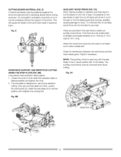
...AND REPETiTiVE CUTTING USING THE STOP PLATE (FIG, BB) Long pieces need extension table support. 1. BB AUXILIARY WOOD FENCE (FIG. Holes are provided in the saw blade in . high by 2-I/2 in the 0 ° bevel position (90 ° to the table). Adjust if necessary. NOTE: This auxiliary fence is... auxiliary wood fence can be constructed of one stop plate is to be mounted to your saw blade to bind and could result in . CUTTING BOWED MATERIAL (FIG. Loosen the knob (1) then slide the extension table to vertical position and retighten the locking bolt. Attach the wood fence securely...
...AND REPETiTiVE CUTTING USING THE STOP PLATE (FIG, BB) Long pieces need extension table support. 1. BB AUXILIARY WOOD FENCE (FIG. Holes are provided in the saw blade in . high by 2-I/2 in the 0 ° bevel position (90 ° to the table). Adjust if necessary. NOTE: This auxiliary fence is... auxiliary wood fence can be constructed of one stop plate is to be mounted to your saw blade to bind and could result in . CUTTING BOWED MATERIAL (FIG. Loosen the knob (1) then slide the extension table to vertical position and retighten the locking bolt. Attach the wood fence securely...


