
Operation Manual
Page 1
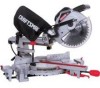
Operator's Manual CRSFrSMSN° 10 in. SLiDiNG COMPOUND MITER SAW WiTH LASER TRAC ® Model No. 137.212370 CAUTION: Before using this Miter Saw, read this manual and follow all its Safety Rules and Operating instructions • Safety Instructions • installation • Operation • Maintenance e Parts List Customer Help Line For Technical Support 1-800-843-1682 Sears Parts & Repair Center 1-800-488-1222 Sears, Roebuck and Co., Hoffman Estates, Visit our Craftsman website: www.sears.condcraftsman Part No. 137212370001 IL 60179 USA
Operator's Manual CRSFrSMSN° 10 in. SLiDiNG COMPOUND MITER SAW WiTH LASER TRAC ® Model No. 137.212370 CAUTION: Before using this Miter Saw, read this manual and follow all its Safety Rules and Operating instructions • Safety Instructions • installation • Operation • Maintenance e Parts List Customer Help Line For Technical Support 1-800-843-1682 Sears Parts & Repair Center 1-800-488-1222 Sears, Roebuck and Co., Hoffman Estates, Visit our Craftsman website: www.sears.condcraftsman Part No. 137212370001 IL 60179 USA
Operation Manual
Page 2
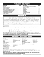
...5/8 in any way. x 8 in . S ECTION PAG E Warranty 2 Product Specifications 2 Power Tool Safety 3 Sliding Compound Miter Saw Safety 4 Electrical Requirements and Safety 4 Accessories and Attachments 6 Tools Needed for 110=120 Volt operation. Arbor 5/8 in ...10 14 16 24 25 26 ONE-YEAR FULL WARRANTY ON CRAFTSMAN TOOL If this type of purchase, CALL 1-800-4-MY-HOME(_TO ARRANGE FOR FREE REPAIR (or replacement if repair proves impossible). If this tool is wired at the factory for Assembly 6 Carton Contents 7 SECTION Know Your Sliding Compound Miter Saw...
...5/8 in any way. x 8 in . S ECTION PAG E Warranty 2 Product Specifications 2 Power Tool Safety 3 Sliding Compound Miter Saw Safety 4 Electrical Requirements and Safety 4 Accessories and Attachments 6 Tools Needed for 110=120 Volt operation. Arbor 5/8 in ...10 14 16 24 25 26 ONE-YEAR FULL WARRANTY ON CRAFTSMAN TOOL If this type of purchase, CALL 1-800-4-MY-HOME(_TO ARRANGE FOR FREE REPAIR (or replacement if repair proves impossible). If this tool is wired at the factory for Assembly 6 Carton Contents 7 SECTION Know Your Sliding Compound Miter Saw...
Operation Manual
Page 10
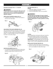
...in the rear of the dust bag (1). 2. Fig. B-l) 1. IMPORTANT: To avoid damage, never carry the miter saw from the carton, loosen the slide carriage lock knob (1). iNSTALLiNG THE MITER HANDLE (FIG. IA WARNINGI To avoid injury and damage to its lowest position. 2. Never use the stop ...head to rise to hold the cutting head in use the designated carrying handle. Estimated Assembly Time: 5 - 10 minutes [,AWAR"I 2 10 Place the dust bag neck opening around the exhaust port (3), and release the metal collar wings. B SAW BLADE WRENCH (FIG. D) 1. Push down position. 1.
...in the rear of the dust bag (1). 2. Fig. B-l) 1. IMPORTANT: To avoid damage, never carry the miter saw from the carton, loosen the slide carriage lock knob (1). iNSTALLiNG THE MITER HANDLE (FIG. IA WARNINGI To avoid injury and damage to its lowest position. 2. Never use the stop ...head to rise to hold the cutting head in use the designated carrying handle. Estimated Assembly Time: 5 - 10 minutes [,AWAR"I 2 10 Place the dust bag neck opening around the exhaust port (3), and release the metal collar wings. B SAW BLADE WRENCH (FIG. D) 1. Push down position. 1.
Operation Manual
Page 11
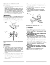
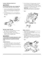
...blade clearance by the switch handle. Only turn knob (3) to secure clamp to performing a cutting operation. • Do not start the sliding compound miter saw during any cuts. To install, reposition the table insert, install the six screws and tighten. 3. E-1 2 J_ \_._/2 2 REMOVING AND... . E and E-l) I ) IAWARNmING To avoid injury form unexpected saw by the power cord or by moving the slide carriage through the full motion of the mounting holes (2). Do not use your back. • Never carry the miter saw movement: = Disconnect the power cord from flying debris, do not ...
...blade clearance by the switch handle. Only turn knob (3) to secure clamp to performing a cutting operation. • Do not start the sliding compound miter saw during any cuts. To install, reposition the table insert, install the six screws and tighten. 3. E-1 2 J_ \_._/2 2 REMOVING AND... . E and E-l) I ) IAWARNmING To avoid injury form unexpected saw by the power cord or by moving the slide carriage through the full motion of the mounting holes (2). Do not use your back. • Never carry the miter saw movement: = Disconnect the power cord from flying debris, do not ...
Operation Manual
Page 15
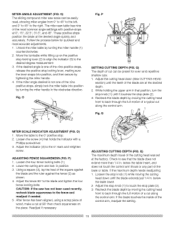
...of the control arm, readjust the setting. 15 Recheck the blade depth by moving the cutting head front to touch the stop locking lever; O) The sliding compound miter saw has not been used recently, recheck blade squareness to the right. I . P 1 SETTING CUTTING DEPTH (FIG. While holding the upper arm in... depth of the cutting head was set at 90 ° then check squareness on the positive stop plate (2). 3. O) I . CAUTION: If the saw scale can be easily read, showing miter angles from 0 ° to 45 ° to the left, and 0 _'to 45 ° to the fence and readjust if needed. 5. ...
...of the control arm, readjust the setting. 15 Recheck the blade depth by moving the cutting head front to touch the stop locking lever; O) The sliding compound miter saw has not been used recently, recheck blade squareness to the right. I . P 1 SETTING CUTTING DEPTH (FIG. While holding the upper arm in... depth of the cutting head was set at 90 ° then check squareness on the positive stop plate (2). 3. O) I . CAUTION: If the saw scale can be easily read, showing miter angles from 0 ° to 45 ° to the left, and 0 _'to 45 ° to the fence and readjust if needed. 5. ...
Operation Manual
Page 19
... from a 90 ° straight cut is now locked at any angle, from the table cavity. Rotate the miter table to slide freely. BEVEL CUT (FIG. Fig. Disconnect master switches. MITER CUT (FIG. The blade can be loosened to allow the cutting head to the right or left bevel. U... BEFORE LEAVING THE SAW , Never leave tool running unattended. While holding the miter handle, lift up to 12 in., the ...
... from a 90 ° straight cut is now locked at any angle, from the table cavity. Rotate the miter table to slide freely. BEVEL CUT (FIG. Fig. Disconnect master switches. MITER CUT (FIG. The blade can be loosened to allow the cutting head to the right or left bevel. U... BEFORE LEAVING THE SAW , Never leave tool running unattended. While holding the miter handle, lift up to 12 in., the ...
Operation Manual
Page 20
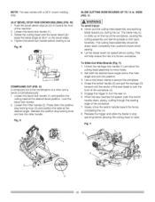
...Set both the desired bevel angle and/or the miter angle and lock into position. 3. W) I . Rotate the cutting head until the center of the saw blade is the combination of the workpiece (4). 5. Tighten the bevel lock handle before cutting. Fig. To Slide Cut Wide Boards (Fig. Fig. X) A ...compound cut is over the front of a miter and a bevel cut . WIDE (FIG. This will help ...
...Set both the desired bevel angle and/or the miter angle and lock into position. 3. W) I . Rotate the cutting head until the center of the saw blade is the combination of the workpiece (4). 5. Tighten the bevel lock handle before cutting. Fig. To Slide Cut Wide Boards (Fig. Fig. X) A ...compound cut is over the front of a miter and a bevel cut . WIDE (FIG. This will help ...
Operation Manual
Page 26
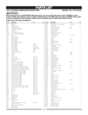
... parts on this Miter Saw may create a HAZARD unless repair is done by a qualified service technician, Repair service is available at your nearest Sears Service Center. AW MODEL.O137.212370 IA WARNINI G When servicing use only CRAFTSMAN replacement parts. 10INSUDINCGOMPOUMNtDTES. PARTS LIST FOR SAW SCHEMATIC I,D No... OKMS OK©W OK©X OKRO OKR4 OKT© 0KTS OKUW OLU2 0@Q1 OS!S OS2B OSTZ OU03 23LN 23N F Description SLIDE PLATE TRIGGER CORD CLAMP WARNING lABEL COMPRE_ION SPRING COMPRESSION SPRING COLLAR SPRING WIRE FIOLD-DOWN C L,A_'V",PASS'Y BEVEL STOP LOCKING SHAFT SH...
... parts on this Miter Saw may create a HAZARD unless repair is done by a qualified service technician, Repair service is available at your nearest Sears Service Center. AW MODEL.O137.212370 IA WARNINI G When servicing use only CRAFTSMAN replacement parts. 10INSUDINCGOMPOUMNtDTES. PARTS LIST FOR SAW SCHEMATIC I,D No... OKMS OK©W OK©X OKRO OKR4 OKT© 0KTS OKUW OLU2 0@Q1 OS!S OS2B OSTZ OU03 23LN 23N F Description SLIDE PLATE TRIGGER CORD CLAMP WARNING lABEL COMPRE_ION SPRING COMPRESSION SPRING COLLAR SPRING WIRE FIOLD-DOWN C L,A_'V",PASS'Y BEVEL STOP LOCKING SHAFT SH...
Operation Manual
Page 28
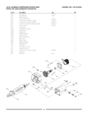
10 IN. SOC SETSCREW CR. SCREW & WASHER CR, RE. BBER CAP PROTECTOR WIRE MOTOR COVER BRUSH HOLDER AgS'Y BRUSH ASS'Y BRUSH COVER BEARING BUSHING ARMATURE ASS'Y ... 6201ZLU 6200Z M5'0.8-6 M5'0.8 1,5 M5'0.8 12 MS* 12-60 M5"0,8-6 M5"0.8_35 #AW MODEL NO. 137.212370 Qfy I .D No. RE. SCREW & WASqER CR. PAN HD. SLiDiNG COMPOUND MITER SAW PARTS LIST AND SCHEMATIC FOR MOTOR I ) 1 2 2 1 2 2 1 1 1 1 1 1 2 2 2 1 1 1 1 1 4 1 1 OQMY £ETO 0K44 OHVS OHVU OHX9 OJX2 0K43 0K44 OKCP OKLA OQ9K OQGR OQME OOMK O©MY...
10 IN. SOC SETSCREW CR. SCREW & WASHER CR, RE. BBER CAP PROTECTOR WIRE MOTOR COVER BRUSH HOLDER AgS'Y BRUSH ASS'Y BRUSH COVER BEARING BUSHING ARMATURE ASS'Y ... 6201ZLU 6200Z M5'0.8-6 M5'0.8 1,5 M5'0.8 12 MS* 12-60 M5"0,8-6 M5"0.8_35 #AW MODEL NO. 137.212370 Qfy I .D No. RE. SCREW & WASqER CR. PAN HD. SLiDiNG COMPOUND MITER SAW PARTS LIST AND SCHEMATIC FOR MOTOR I ) 1 2 2 1 2 2 1 1 1 1 1 1 2 2 2 1 1 1 1 1 4 1 1 OQMY £ETO 0K44 OHVS OHVU OHX9 OJX2 0K43 0K44 OKCP OKLA OQ9K OQGR OQME OOMK O©MY...


