End User License Agreement
Page 2
... identified as an upgrade, you fail to comply with /for the upgrade. The initial user of the Software Product may not reverse engineer, decompile, or disassemble the Software Product, except and only to the extent that the right to the transfer, the end user receiving the transferred product must include all...
... identified as an upgrade, you fail to comply with /for the upgrade. The initial user of the Software Product may not reverse engineer, decompile, or disassemble the Software Product, except and only to the extent that the right to the transfer, the end user receiving the transferred product must include all...

Maintenance and Service Guide
Page 1
b Maintenance and Service Guide Evo Notebook N800c, Evo Notebook N800v, Evo Notebook N800w, and Presario 2800 Mobile PC Series Document Part Number: 268135-003 January 2003 This guide is a troubleshooting reference used for maintaining and servicing the notebook. It provides comprehensive information on identifying computer features, components, and spare parts, troubleshooting computer problems, and performing computer disassembly procedures.
b Maintenance and Service Guide Evo Notebook N800c, Evo Notebook N800v, Evo Notebook N800w, and Presario 2800 Mobile PC Series Document Part Number: 268135-003 January 2003 This guide is a troubleshooting reference used for maintaining and servicing the notebook. It provides comprehensive information on identifying computer features, components, and spare parts, troubleshooting computer problems, and performing computer disassembly procedures.

Maintenance and Service Guide
Page 4
... to Removable Drives 4-3 4.4 Preventing Electrostatic Damage 4-4 4.5 Packaging and Transporting Precautions 4-4 4.6 Workstation Precautions 4-5 4.7 Grounding Equipment and Methods 4-6 5 Removal and Replacement Procedures 5.1 Serial Number 5-2 5.2 Disassembly Sequence Chart 5-2 5.3 Preparing the Computer for Disassembly 5-4 5.4 Computer Feet 5-9 5.5 Memory Expansion Board 5-9 5.6 Mini PCI Communications Board 5-12 5.7 Connector Cover 5-15 5.8 LED Cover 5-16 5.9 Keyboard 5-18 5.10 Display 5-22 5.11...
... to Removable Drives 4-3 4.4 Preventing Electrostatic Damage 4-4 4.5 Packaging and Transporting Precautions 4-4 4.6 Workstation Precautions 4-5 4.7 Grounding Equipment and Methods 4-6 5 Removal and Replacement Procedures 5.1 Serial Number 5-2 5.2 Disassembly Sequence Chart 5-2 5.3 Preparing the Computer for Disassembly 5-4 5.4 Computer Feet 5-9 5.5 Memory Expansion Board 5-9 5.6 Mini PCI Communications Board 5-12 5.7 Connector Cover 5-15 5.8 LED Cover 5-16 5.9 Keyboard 5-18 5.10 Display 5-22 5.11...

Maintenance and Service Guide
Page 48
...any battery packs at this time. 6. All passwords and all CMOS settings have been cleared. Product Description 1.3 Clearing a Password If the notebook you are servicing has an unknown password, follow these steps to Section 5.17, "Disk Cell RTC Battery"). 3. Connect AC power to ...Section 5.3, "Preparing the Computer for Disassembly," for more information). 2. Turn on the computer. Maintenance and Service Guide 1-43 Wait approximately five minutes. 4. These steps also clear CMOS:...
...any battery packs at this time. 6. All passwords and all CMOS settings have been cleared. Product Description 1.3 Clearing a Password If the notebook you are servicing has an unknown password, follow these steps to Section 5.17, "Disk Cell RTC Battery"). 3. Connect AC power to ...Section 5.3, "Preparing the Computer for Disassembly," for more information). 2. Turn on the computer. Maintenance and Service Guide 1-43 Wait approximately five minutes. 4. These steps also clear CMOS:...

Maintenance and Service Guide
Page 60
... board ■ Hard drive ■ Display ■ Keyboard/TouchPad or pointing stick ■ Audio ■ Intel Mobile Pentium 4 processors with SpeedStep technology ■ Fan ■ PC Card ■ Modem or modem/NIC The computer uses an electrical fan for disassembly steps.
... board ■ Hard drive ■ Display ■ Keyboard/TouchPad or pointing stick ■ Audio ■ Intel Mobile Pentium 4 processors with SpeedStep technology ■ Fan ■ PC Card ■ Modem or modem/NIC The computer uses an electrical fan for disassembly steps.

Maintenance and Service Guide
Page 113
... reassembly process. Ensure that cables are placed in their proper locations during removal and insertion. Plastic Parts Using excessive force during disassembly and assembly procedures. ✎ As you remove each subassembly from the computer, place the subassembly (and all cases, avoid ...Removal and Replacement Preliminaries 4.2 Service Considerations The following sections include some of the considerations that you should keep in mind during disassembly and reassembly can damage the computer. 4-2 Maintenance and Service Guide In all accompanying screws) away from the work area to...
... reassembly process. Ensure that cables are placed in their proper locations during removal and insertion. Plastic Parts Using excessive force during disassembly and assembly procedures. ✎ As you remove each subassembly from the computer, place the subassembly (and all cases, avoid ...Removal and Replacement Preliminaries 4.2 Service Considerations The following sections include some of the considerations that you should keep in mind during disassembly and reassembly can damage the computer. 4-2 Maintenance and Service Guide In all accompanying screws) away from the work area to...

Maintenance and Service Guide
Page 120
Make special note of each screw size and location during disassembly. There are removed during removal and replacement. Refer to Appendix C, "Screw Listing," for detailed information on screw sizes, locations, and usage. Maintenance and Service Guide 5-1 Phillips P1 screws are 48 screws, in nine different sizes, that must be removed, replaced, and loosened when servicing the computer. 5 Removal and Replacement Procedures This chapter provides removal and replacement procedures.
Make special note of each screw size and location during disassembly. There are removed during removal and replacement. Refer to Appendix C, "Screw Listing," for detailed information on screw sizes, locations, and usage. Maintenance and Service Guide 5-1 Phillips P1 screws are 48 screws, in nine different sizes, that must be removed, replaced, and loosened when servicing the computer. 5 Removal and Replacement Procedures This chapter provides removal and replacement procedures.

Maintenance and Service Guide
Page 121
Serial Number Location 5.2 Disassembly Sequence Chart Use the chart below to determine the section number to Compaq when requesting information or ordering spare parts. Removal and Replacement Procedures 5.1 Serial Number Report the computer serial number to be referenced when removing computer components. Section 5.3 Table 5-1 Disassembly Sequence Chart Description Preparing the computer for disassembly Battery pack # of the computer (Figure 5-1). The serial number is located on the bottom of Screws Removed 0 5-2 Maintenance and Service Guide Figure 5-1.
Serial Number Location 5.2 Disassembly Sequence Chart Use the chart below to determine the section number to Compaq when requesting information or ordering spare parts. Removal and Replacement Procedures 5.1 Serial Number Report the computer serial number to be referenced when removing computer components. Section 5.3 Table 5-1 Disassembly Sequence Chart Description Preparing the computer for disassembly Battery pack # of the computer (Figure 5-1). The serial number is located on the bottom of Screws Removed 0 5-2 Maintenance and Service Guide Figure 5-1.

Maintenance and Service Guide
Page 122
Removal and Replacement Procedures Table 5-1 Disassembly Sequence Chart (Continued) Section 5.3 (continued) Description MultiBay device Hard drive 5.4 Computer feet 5.5 Memory expansion board 5.6 Mini PCI communications board 5.7 Connector cover 5.8 LED cover 5.9 Keyboard 5.10 ...
Removal and Replacement Procedures Table 5-1 Disassembly Sequence Chart (Continued) Section 5.3 (continued) Description MultiBay device Hard drive 5.4 Computer feet 5.5 Memory expansion board 5.6 Mini PCI communications board 5.7 Connector cover 5.8 LED cover 5.9 Keyboard 5.10 ...

Maintenance and Service Guide
Page 123
... the battery pack out of the computer (Figure 5-2). Figure 5-2. Turn off the computer. 2. c. Removal and Replacement Procedures 5.3 Preparing the Computer for Disassembly Perform the following these steps: a. Remove the battery pack by following steps before disassembling the computer: 1. Slide and hold the battery release latch 1 toward the back of the battery bay 2.
... the battery pack out of the computer (Figure 5-2). Figure 5-2. Turn off the computer. 2. c. Removal and Replacement Procedures 5.3 Preparing the Computer for Disassembly Perform the following these steps: a. Remove the battery pack by following steps before disassembling the computer: 1. Slide and hold the battery release latch 1 toward the back of the battery bay 2.

Maintenance and Service Guide
Page 129
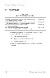
... Maintenance and Service Guide Turn the computer bottom side up with silver finish for Presario 2800 models and carbon finish for disassembly (Section 5.3). 2. Prepare the computer for Evo Notebook N800c, N800v, and N800w models. These covers are available with the rear panel facing forward. 3. Remove the cover 3. Lift the front edge of the cover...
... Maintenance and Service Guide Turn the computer bottom side up with silver finish for Presario 2800 models and carbon finish for disassembly (Section 5.3). 2. Prepare the computer for Evo Notebook N800c, N800v, and N800w models. These covers are available with the rear panel facing forward. 3. Remove the cover 3. Lift the front edge of the cover...

Maintenance and Service Guide
Page 131
Prepare the computer for disassembly (Section 5.3). 2. Removal and Replacement Procedures 5.6 Mini PCI Communications Board Mini PCI Communication Boards Spare Part Number Information U.S. Turn the computer bottom side up with the rear panel facing forward. 5-12 Maintenance and Service Guide modem International modem 285286-001 285287-001 1.
Prepare the computer for disassembly (Section 5.3). 2. Removal and Replacement Procedures 5.6 Mini PCI Communications Board Mini PCI Communication Boards Spare Part Number Information U.S. Turn the computer bottom side up with the rear panel facing forward. 5-12 Maintenance and Service Guide modem International modem 285286-001 285287-001 1.

Maintenance and Service Guide
Page 134
...Miscellaneous Plastics/Hardware Kit, spare part number 285261-001 for Presario 2800 models, and spare part number 286868-001 for Evo Notebook N800c, N800v, and N800w models. Open the connector cover. 5. This cover is available with the rear panel facing forward. 3. Turn the...with silver finish for Presario 2800 models and carbon finish for Evo Notebook N800c, N800v, and N800w models. 1. Remove the connector cover from the base enclosure 2. Maintenance and Service Guide 5-15 Prepare the computer for disassembly (Section 5.3). 2. Removing the Connector Cover Reverse the above ...
...Miscellaneous Plastics/Hardware Kit, spare part number 285261-001 for Presario 2800 models, and spare part number 286868-001 for Evo Notebook N800c, N800v, and N800w models. Open the connector cover. 5. This cover is available with the rear panel facing forward. 3. Turn the...with silver finish for Presario 2800 models and carbon finish for Evo Notebook N800c, N800v, and N800w models. 1. Remove the connector cover from the base enclosure 2. Maintenance and Service Guide 5-15 Prepare the computer for disassembly (Section 5.3). 2. Removing the Connector Cover Reverse the above ...

Maintenance and Service Guide
Page 135
Turn the computer bottom side up with the rear panel facing forward. 3. Turn the computer top side up with the front facing forward. 5. Remove the two black PM2.0 × 10.0 screws that secure the LED cover to the base enclosure (Figure 5-13). Removal and Replacement Procedures 5.8 LED Cover LED Cover Spare Part Number Information LED cover 288503-001 1. Figure 5-13. Open the computer. 5-16 Maintenance and Service Guide Removing the LED Cover Screws 4. Prepare the computer for disassembly (Section 5.3). 2.
Turn the computer bottom side up with the rear panel facing forward. 3. Turn the computer top side up with the front facing forward. 5. Remove the two black PM2.0 × 10.0 screws that secure the LED cover to the base enclosure (Figure 5-13). Removal and Replacement Procedures 5.8 LED Cover LED Cover Spare Part Number Information LED cover 288503-001 1. Figure 5-13. Open the computer. 5-16 Maintenance and Service Guide Removing the LED Cover Screws 4. Prepare the computer for disassembly (Section 5.3). 2.
Maintenance and Service Guide
Page 138
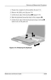
Prepare the computer for disassembly (Section 5.3). 2. Lift the back edge of the computer 2. 5. Releasing the Keyboard Maintenance and Service Guide 5-19 Removal and Replacement Procedures 1. Slide the keyboard toward the back of the keyboard and swing it forward 3 until it rests on the palm rest. Lift the back edge of the keyboard 1 (Figure 5-15). 4. Figure 5-15. Remove the LED cover (Section 5.8). 3.
Prepare the computer for disassembly (Section 5.3). 2. Lift the back edge of the computer 2. 5. Releasing the Keyboard Maintenance and Service Guide 5-19 Removal and Replacement Procedures 1. Slide the keyboard toward the back of the keyboard and swing it forward 3 until it rests on the palm rest. Lift the back edge of the keyboard 1 (Figure 5-15). 4. Figure 5-15. Remove the LED cover (Section 5.8). 3.

Maintenance and Service Guide
Page 141
..., XGA 14-inch, XGA MultiPort cover 322510-001 285265-001 285264-001 285263-001 285262-001 289037-001 1. Prepare the computer for use with Evo Notebook N800c, N800v, and N800w models 15-inch, UXGA WVA 15-inch, UXGA 15-inch, SXGA+ 15-inch, XGA 14-inch, XGA 322511-001 286872-001 286871-001...
..., XGA 14-inch, XGA MultiPort cover 322510-001 285265-001 285264-001 285263-001 285262-001 289037-001 1. Prepare the computer for use with Evo Notebook N800c, N800v, and N800w models 15-inch, UXGA WVA 15-inch, UXGA 15-inch, SXGA+ 15-inch, XGA 14-inch, XGA 322511-001 286872-001 286871-001...
Maintenance and Service Guide
Page 145
LED cover (Section 5.8) b. for use only with Evo Notebook N800c, N800v, and N800w models) 322504-001 322502-001 322503-001 323747-001 1. for use only with Evo Notebook N800c and Evo Notebook N800v models) For TouchPad only (silver finish for use with Evo Notebook N800w models) For Dual Point (TouchPad and Point Stick; Removal and Replacement Procedures.... 5-26 Maintenance and Service Guide Prepare the computer for use with Presario 2800 models) For TouchPad only (carbon finish for disassembly (Section 5.3) and remove the following components: a. Display (Section 5.10) 2.
LED cover (Section 5.8) b. for use only with Evo Notebook N800c, N800v, and N800w models) 322504-001 322502-001 322503-001 323747-001 1. for use only with Evo Notebook N800c and Evo Notebook N800v models) For TouchPad only (silver finish for use with Evo Notebook N800w models) For Dual Point (TouchPad and Point Stick; Removal and Replacement Procedures.... 5-26 Maintenance and Service Guide Prepare the computer for use with Presario 2800 models) For TouchPad only (carbon finish for disassembly (Section 5.3) and remove the following components: a. Display (Section 5.10) 2.

Maintenance and Service Guide
Page 150
Position the top cover bottom side up with the front facing forward. Prepare the computer for disassembly (Section 5.3) and remove the following components: a. Top cover (Section 5.11) 2. Keyboard and shield (Section 5.9) c. LED cover (Section 5.8) b. Removal and Replacement Procedures 5.12 Speaker Assembly Speaker Assembly Spare Part Number Information Speaker assembly 285266-001 1. Display (Section 5.10) d. Maintenance and Service Guide 5-31
Position the top cover bottom side up with the front facing forward. Prepare the computer for disassembly (Section 5.3) and remove the following components: a. Top cover (Section 5.11) 2. Keyboard and shield (Section 5.9) c. LED cover (Section 5.8) b. Removal and Replacement Procedures 5.12 Speaker Assembly Speaker Assembly Spare Part Number Information Speaker assembly 285266-001 1. Display (Section 5.10) d. Maintenance and Service Guide 5-31
Maintenance and Service Guide
Page 152
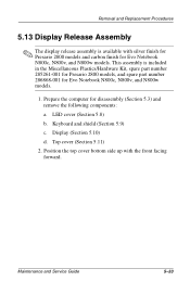
Maintenance and Service Guide 5-33 Top cover (Section 5.11) 2. Prepare the computer for Evo Notebook N800c, N800v, and N800w models. Removal and Replacement Procedures 5.13 Display Release Assembly ✎ The display release assembly is included in the ...Miscellaneous Plastics/Hardware Kit, spare part number 285261-001 for Presario 2800 models, and spare part number 286868-001 for Evo Notebook N800c, N800v, and N800w models. 1. Keyboard and shield (Section 5.9) c. LED cover (Section 5.8) b. Display (Section 5.10) d. Position the top cover bottom...
Maintenance and Service Guide 5-33 Top cover (Section 5.11) 2. Prepare the computer for Evo Notebook N800c, N800v, and N800w models. Removal and Replacement Procedures 5.13 Display Release Assembly ✎ The display release assembly is included in the ...Miscellaneous Plastics/Hardware Kit, spare part number 285261-001 for Presario 2800 models, and spare part number 286868-001 for Evo Notebook N800c, N800v, and N800w models. 1. Keyboard and shield (Section 5.9) c. LED cover (Section 5.8) b. Display (Section 5.10) d. Position the top cover bottom...

Maintenance and Service Guide
Page 154
Removal and Replacement Procedures 5.14 TouchPad TouchPad and TouchButton Board Spare Part Number Information TouchPad TouchButton board for Dual Point TouchButton board for disassembly (Section 5.3) and remove the following components: a. Speaker assembly (Section 5.12) Maintenance and Service Guide 5-35 LED cover (Section 5.8) b. Keyboard and shield (Section 5.9) c. Display (Section 5.10) d. Top cover (Section 5.11) e. Prepare the computer for TouchPad 285258-001 285259-001 285260-001 1.
Removal and Replacement Procedures 5.14 TouchPad TouchPad and TouchButton Board Spare Part Number Information TouchPad TouchButton board for Dual Point TouchButton board for disassembly (Section 5.3) and remove the following components: a. Speaker assembly (Section 5.12) Maintenance and Service Guide 5-35 LED cover (Section 5.8) b. Keyboard and shield (Section 5.9) c. Display (Section 5.10) d. Top cover (Section 5.11) e. Prepare the computer for TouchPad 285258-001 285259-001 285260-001 1.


