Hard Drive White Paper
Page 4
... BIOS Required Notebook Platform HP Compaq Business nc8000 HP Compaq Business nw8000 HP Compaq Business nc6000 HP Compaq Business nc4000 Series HP Compaq Business nx9000 Series HP Compaq Business nx5000 Compaq Evo N620c Compaq Evo N610c/v Compaq Evo N600c Compaq Evo N800c Compaq Evo N410c Compaq Evo N400c BIOS Version...Hard Drive Mounting Screw All HP and Compaq branded commercial and SMB notebooks come equipped with one of the following commercial notebooks is greatly increased. Without the hard drive mounting screws, the chance of the notebook, they can be replaced from the notebook...
... BIOS Required Notebook Platform HP Compaq Business nc8000 HP Compaq Business nw8000 HP Compaq Business nc6000 HP Compaq Business nc4000 Series HP Compaq Business nx9000 Series HP Compaq Business nx5000 Compaq Evo N620c Compaq Evo N610c/v Compaq Evo N600c Compaq Evo N800c Compaq Evo N410c Compaq Evo N400c BIOS Version...Hard Drive Mounting Screw All HP and Compaq branded commercial and SMB notebooks come equipped with one of the following commercial notebooks is greatly increased. Without the hard drive mounting screws, the chance of the notebook, they can be replaced from the notebook...
Hardware Guide, Compaq Notebook Series
Page 7
Contents Increasing Memory 7-4 Displaying Memory Information 7-4 Removing or Inserting a Memory Board 7-5 Replacing the Primary Hard Drive 7-10 Finding Mini PCI and MultiPort Information 7-12 8 Specifications Regulatory Agency Series Numbers 8-1 Notebook Dimensions 8-2 Operating Environment 8-2 Rated Input Power 8-3 Modem Specifications 8-3 Finding More Environmental Information 8-4 Index Hardware Guide vii
Contents Increasing Memory 7-4 Displaying Memory Information 7-4 Removing or Inserting a Memory Board 7-5 Replacing the Primary Hard Drive 7-10 Finding Mini PCI and MultiPort Information 7-12 8 Specifications Regulatory Agency Series Numbers 8-1 Notebook Dimensions 8-2 Operating Environment 8-2 Rated Input Power 8-3 Modem Specifications 8-3 Finding More Environmental Information 8-4 Index Hardware Guide vii
Hardware Guide, Compaq Notebook Series
Page 65
... to use more information about replacing the primary hard drive, refer in this section. Ä CAUTION: To prevent damage to the notebook or a drive and loss of magnetism and will not damage a hard drive. ■ Do not spray a drive with cleaners. ■ Avoid exposing a drive to liquids or temperature extremes. ■ If you insert a drive, use x-rays instead of work...
... to use more information about replacing the primary hard drive, refer in this section. Ä CAUTION: To prevent damage to the notebook or a drive and loss of magnetism and will not damage a hard drive. ■ Do not spray a drive with cleaners. ■ Avoid exposing a drive to liquids or temperature extremes. ■ If you insert a drive, use x-rays instead of work...
Hardware Guide, Compaq Notebook Series
Page 107
Hardware Upgrades Replacing the Primary Hard Drive Any hard drive in the hard drive bay is off and not in Hibernation. ■ To verify that the notebook is the primary hard drive. Do not remove the hard drive while the notebook is on, in Standby, or in Hibernation, briefly press the power button. Remove the primary hard drive only for repair or replacement. Ä CAUTION: To prevent...
Hardware Upgrades Replacing the Primary Hard Drive Any hard drive in the hard drive bay is off and not in Hibernation. ■ To verify that the notebook is the primary hard drive. Do not remove the hard drive while the notebook is on, in Standby, or in Hibernation, briefly press the power button. Remove the primary hard drive only for repair or replacement. Ä CAUTION: To prevent...
Hardware Guide, Compaq Notebook Series
Page 109
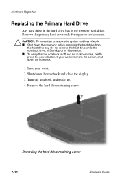
... mini PCI or MultiPort device, this guide to the documentation included with the notebook. Hardware Upgrades 7. If you have inserted a hard drive, reinsert the hard drive retaining screw. (If you removed but did not replace a hard drive, put the retaining screw in a safe place.) Replacing the hard drive retaining screw Finding Mini PCI and MultiPort Information For information about the light...
... mini PCI or MultiPort device, this guide to the documentation included with the notebook. Hardware Upgrades 7. If you have inserted a hard drive, reinsert the hard drive retaining screw. (If you removed but did not replace a hard drive, put the retaining screw in a safe place.) Replacing the hard drive retaining screw Finding Mini PCI and MultiPort Information For information about the light...
Hardware Guide, Compaq Notebook Series
Page 115
... and lights 3-9 MultiBay (optional), inserting 3-4 MultiBay (optional), removing 3-4 MultiBay (optional), replacing with weight saver 1-20 MultiBay (optional), vs. primary 3-2 primary, inserting 3-3 primary, removing...low-battery conditions, resolving 3-11 running notebook on and off 2-7 board memory 7-4 mini PCI 1-14 modem 1-14 brightness,...PC Card eject 7-3 pointing stick 2-2 power 1-6 scroll 2-1 TouchPad 2-1 volume 5-1 See also key(s); network 1-19 Index-2 Hardware Guide latch(es); switch, display C cable audio (optional) 5-8 DC (optional) 1-10 modem 1-19 modem vs. MultiBay; hard drive...
... and lights 3-9 MultiBay (optional), inserting 3-4 MultiBay (optional), removing 3-4 MultiBay (optional), replacing with weight saver 1-20 MultiBay (optional), vs. primary 3-2 primary, inserting 3-3 primary, removing...low-battery conditions, resolving 3-11 running notebook on and off 2-7 board memory 7-4 mini PCI 1-14 modem 1-14 brightness,...PC Card eject 7-3 pointing stick 2-2 power 1-6 scroll 2-1 TouchPad 2-1 volume 5-1 See also key(s); network 1-19 Index-2 Hardware Guide latch(es); switch, display C cable audio (optional) 5-8 DC (optional) 1-10 modem 1-19 modem vs. MultiBay; hard drive...
Hardware Guide, Compaq Notebook Series
Page 116
...connecting 5-7, 6-1 switching image to 2-9 cap, replacing pointing stick 1-20 caps lock light 1-5 card and socket services, PC Card 7-2 card. drives CD-RW. See board; PC Card CD audio, hotkeys for 2-10 avoiding Standby...Compaq utilities. MultiBay composite-video device connecting 5-7, 6-1 turning off and on 5-9 Computer Setup accessing 2-17 changing language of 4-15 inserting 4-11 removing (power available) 4-12 removing (power unavailable) 4-13 See also CD drive (optional); See software compartment memory 1-14, 7-6 mini PCI 1-14 See also battery bay; hard drive bay; media, drive CD drive...
...connecting 5-7, 6-1 switching image to 2-9 cap, replacing pointing stick 1-20 caps lock light 1-5 card and socket services, PC Card 7-2 card. drives CD-RW. See board; PC Card CD audio, hotkeys for 2-10 avoiding Standby...Compaq utilities. MultiBay composite-video device connecting 5-7, 6-1 turning off and on 5-9 Computer Setup accessing 2-17 changing language of 4-15 inserting 4-11 removing (power available) 4-12 removing (power unavailable) 4-13 See also CD drive (optional); See software compartment memory 1-14, 7-6 mini PCI 1-14 See also battery bay; hard drive bay; media, drive CD drive...

Hardware Guide, Compaq Notebook Series
Page 124
... connector 1-16 docking retraint latch recess for 1-16 drives supported by 4-1 PS/2 connector on TouchPad models 2-1 replacing pointing stick cap 1-20 setting preferences 2-4 port infrared 6-4 See also connector(s); hard drive Product Key number 1-17 projector, overhead. port; Index... P PAL, PAL-M television formats 5-10 parallel connector connecting device to 6-1 identifying 1-10 PC Card biometric (...
... connector 1-16 docking retraint latch recess for 1-16 drives supported by 4-1 PS/2 connector on TouchPad models 2-1 replacing pointing stick cap 1-20 setting preferences 2-4 port infrared 6-4 See also connector(s); hard drive Product Key number 1-17 projector, overhead. port; Index... P PAL, PAL-M television formats 5-10 parallel connector connecting device to 6-1 identifying 1-10 PC Card biometric (...

Maintenance and Service Guide
Page 60
... a 3-inch (7.6 cm) clearance on automatically when high temperature conditions exist. Exhaust air is designed to identify replacement parts, and Chapter 5, "Removal and Replacement Procedures," for ventilation. Maintenance and Service Guide 1-55 Refer to Chapter 3, "Illustrated Parts Catalog," to turn on...features of the computer. The system board provides the following device connections: ■ Memory expansion board ■ Hard drive ■ Display ■ Keyboard/TouchPad or pointing stick ■ Audio ■ Intel Mobile Pentium 4 processors with SpeedStep technology ■...
... a 3-inch (7.6 cm) clearance on automatically when high temperature conditions exist. Exhaust air is designed to identify replacement parts, and Chapter 5, "Removal and Replacement Procedures," for ventilation. Maintenance and Service Guide 1-55 Refer to Chapter 3, "Illustrated Parts Catalog," to turn on...features of the computer. The system board provides the following device connections: ■ Memory expansion board ■ Hard drive ■ Display ■ Keyboard/TouchPad or pointing stick ■ Audio ■ Intel Mobile Pentium 4 processors with SpeedStep technology ■...

Maintenance and Service Guide
Page 81
... to Section 2.12, No OS Loading from hard drive? Y Format hard drive and bring to bootable C:\ prompt. Reseat hard drive. Hard drive formatted? N Go to Section 2.13, No OS Loading from Hard Drive, Part 1. Load OS using Restore CD (if applicable). Replace system board. Done Remove diskette and reboot. Y Hard drive accessible? N Done N Boot from Hard Drive, Part 3. Replace hard drive. 2. Done N Hard drive partitioned? Y 1. Computer booted? Y N Go to Section...
... to Section 2.12, No OS Loading from hard drive? Y Format hard drive and bring to bootable C:\ prompt. Reseat hard drive. Hard drive formatted? N Go to Section 2.13, No OS Loading from Hard Drive, Part 1. Load OS using Restore CD (if applicable). Replace system board. Done Remove diskette and reboot. Y Hard drive accessible? N Done N Boot from Hard Drive, Part 3. Replace hard drive. 2. Done N Hard drive partitioned? Y 1. Computer booted? Y N Go to Section...

Maintenance and Service Guide
Page 82
N System files on diskette? N Can bad sectors be fixed? N Replace hard drive. Run diagnostics and follow recommendations. Boot from hard drive? N Run SCANDISK and check for bad sectors. N Y Diagnostics on hard drive? Done 2-22 Maintenance and Service Guide Y OS loading from hard drive? N Fix bad sectors. Done Replace hard drive. Y Virus on hard drive? Y Clean virus. Y Install OS and reboot. Troubleshooting Flowchart 2.12-No OS...
N System files on diskette? N Can bad sectors be fixed? N Replace hard drive. Run diagnostics and follow recommendations. Boot from hard drive? N Run SCANDISK and check for bad sectors. N Y Diagnostics on hard drive? Done 2-22 Maintenance and Service Guide Y OS loading from hard drive? N Fix bad sectors. Done Replace hard drive. Y Virus on hard drive? Y Clean virus. Y Install OS and reboot. Troubleshooting Flowchart 2.12-No OS...
Maintenance and Service Guide
Page 87
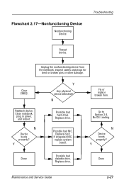
... properly? Unplug the nonfunctioning device from the notebook, inspect cables and plugs for bent or broken pins or other damage. Replace drive. If integrated NIC, replace system board. Done Maintenance and Service Guide 2-27 Flowchart 2.17-Nonfunctioning Device Nonfunctioning Device. Close notebook, plug in power, and reboot. N Possible bad hard drive. Replace drive. Clear CMOS. Y Done Possible bad diskette...
... properly? Unplug the nonfunctioning device from the notebook, inspect cables and plugs for bent or broken pins or other damage. Replace drive. If integrated NIC, replace system board. Done Maintenance and Service Guide 2-27 Flowchart 2.17-Nonfunctioning Device Nonfunctioning Device. Close notebook, plug in power, and reboot. N Possible bad hard drive. Replace drive. Clear CMOS. Y Done Possible bad diskette...
Maintenance and Service Guide
Page 114
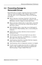
...Replacement Preliminaries 4.3 Preventing Damage to Removable Drives Removable drives are unsure whether the computer is off or in Hibernation, turn the computer on surfaces that have magnetic fields, such as monitors or speakers. ■ Avoid exposing a drive to temperature extremes or to a removable drive...observe the following precautions: ■ Before removing or inserting a hard drive, shut down . ■ Before removing a diskette drive or optical drive, ensure that a diskette or disc is closed. ■ Before handling a drive, ensure that have at least one inch of shock-proof ...
...Replacement Preliminaries 4.3 Preventing Damage to Removable Drives Removable drives are unsure whether the computer is off or in Hibernation, turn the computer on surfaces that have magnetic fields, such as monitors or speakers. ■ Avoid exposing a drive to temperature extremes or to a removable drive...observe the following precautions: ■ Before removing or inserting a hard drive, shut down . ■ Before removing a diskette drive or optical drive, ensure that a diskette or disc is closed. ■ Before handling a drive, ensure that have at least one inch of shock-proof ...

Maintenance and Service Guide
Page 122
Removal and Replacement Procedures Table 5-1 Disassembly Sequence Chart (Continued) Section 5.3 (continued) Description MultiBay device Hard drive 5.4 Computer feet 5.5 Memory expansion board 5.6 Mini PCI communications board 5.7 Connector cover 5.8 LED cover 5.9 Keyboard 5.10 Display 5.11...Processor 5.17 Disk cell RTC battery 5.18 System board 5.19 Modem cable # of Screws Removed 0 1 to remove hard drive 2 to separate hard drive bezel from hard drive 0 1 loosened 1 loosened 2 2 2 to remove keyboard shield 4 16 0 2 4 4 loosened 0 0 5 0 Maintenance and Service Guide 5-3
Removal and Replacement Procedures Table 5-1 Disassembly Sequence Chart (Continued) Section 5.3 (continued) Description MultiBay device Hard drive 5.4 Computer feet 5.5 Memory expansion board 5.6 Mini PCI communications board 5.7 Connector cover 5.8 LED cover 5.9 Keyboard 5.10 Display 5.11...Processor 5.17 Disk cell RTC battery 5.18 System board 5.19 Modem cable # of Screws Removed 0 1 to remove hard drive 2 to separate hard drive bezel from hard drive 0 1 loosened 1 loosened 2 2 2 to remove keyboard shield 4 16 0 2 4 4 loosened 0 0 5 0 Maintenance and Service Guide 5-3
Maintenance and Service Guide
Page 126
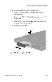
Remove the hard drive by following these steps: a. b. Remove the PM3.0 × 4.0 hard drive retention screw 1 (Figure 5-5). Slide the hard drive forward 2 to unseat the hard drive connector from the system board. d. Turn the computer bottom side up with the left side facing forward. Figure 5-5. Removing the Hard Drive Maintenance and Service Guide 5-7 Remove the hard drive. Removal and Replacement Procedures 6. c.
Remove the hard drive by following these steps: a. b. Remove the PM3.0 × 4.0 hard drive retention screw 1 (Figure 5-5). Slide the hard drive forward 2 to unseat the hard drive connector from the system board. d. Turn the computer bottom side up with the left side facing forward. Figure 5-5. Removing the Hard Drive Maintenance and Service Guide 5-7 Remove the hard drive. Removal and Replacement Procedures 6. c.

Maintenance and Service Guide
Page 127
Removal and Replacement Procedures 7. Slide the hard drive bezel forward to install the hard drive and hard drive bezel. 5-8 Maintenance and Service Guide Removing the Hard Drive Bezel Hard Drive Bezel Spare Part Number Information Hard drive bezel with silver finish for use with Presario 2800 models Hard drive bezel with carbon finish for use with Evo Notebook N800c, N800v, and N800w models 286874-001 286875-001 Reverse the...
Removal and Replacement Procedures 7. Slide the hard drive bezel forward to install the hard drive and hard drive bezel. 5-8 Maintenance and Service Guide Removing the Hard Drive Bezel Hard Drive Bezel Spare Part Number Information Hard drive bezel with silver finish for use with Presario 2800 models Hard drive bezel with carbon finish for use with Evo Notebook N800c, N800v, and N800w models 286874-001 286875-001 Reverse the...
Maintenance and Service Guide
Page 146
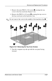
Remove the PM2.0 × 4.0 screw 2 securing the top cover to the base enclosure (Figure 5-21). 4. Maintenance and Service Guide 5-27 Removal and Replacement Procedures 3. Removing the Top Cover Screws 5. Turn the computer top side up with the rear panel facing forward. Figure 5-21. Remove the nine PM2.0 × 8.0 screws 1 securing the top cover to the base enclosure in the hard drive bay. ✎ Do not remove the screw in the middle of the hard drive bay 3.
Remove the PM2.0 × 4.0 screw 2 securing the top cover to the base enclosure (Figure 5-21). 4. Maintenance and Service Guide 5-27 Removal and Replacement Procedures 3. Removing the Top Cover Screws 5. Turn the computer top side up with the rear panel facing forward. Figure 5-21. Remove the nine PM2.0 × 8.0 screws 1 securing the top cover to the base enclosure in the hard drive bay. ✎ Do not remove the screw in the middle of the hard drive bay 3.

Maintenance and Service Guide
Page 218
... 1-50 front components 1-45 function keys 1-50 G grounding equipment and methods 4-6 H hard drive OS loading problems 2-20 removal 5-7, 5-8 spare part numbers 3-9, 3-19 specifications 6-7 hard drive bay 1-46, 1-54 hard drive bezel removal 5-8 spare part numbers 3-9 hard drive retention screw 1-54 headphone jack location 1-48 pin assignments A-6 hinge covers illustrated 3-16 ...left side components 1-47 Logo Kit, spare part number 3-20 M mass storage devices 3-18 memory expansion board replacement 5-9 spare part numbers 3-15 memory expansion compartment 1-54 Maintenance and Service Guide Index-3
... 1-50 front components 1-45 function keys 1-50 G grounding equipment and methods 4-6 H hard drive OS loading problems 2-20 removal 5-7, 5-8 spare part numbers 3-9, 3-19 specifications 6-7 hard drive bay 1-46, 1-54 hard drive bezel removal 5-8 spare part numbers 3-9 hard drive retention screw 1-54 headphone jack location 1-48 pin assignments A-6 hinge covers illustrated 3-16 ...left side components 1-47 Logo Kit, spare part number 3-20 M mass storage devices 3-18 memory expansion board replacement 5-9 spare part numbers 3-15 memory expansion compartment 1-54 Maintenance and Service Guide Index-3

Maintenance and Service Guide
Page 220
... bezel illustrated 3-16 removal 5-48 PC Card eject button 1-48 PC Card slot 1-48 PC Card slot space saver 3-16 plastic parts 4-2 ... time clock (RTC) battery removal 5-42 spare part number 3-11, 5-42 rear panel components 1-47 removal and replacement preliminaries 4-1 procedures 5-1 right side components 1-45 RJ-11 jack location 1-48 pin assignments A-2 RJ-45 jack location... specifications AC adapter 6-13 battery 6-13 CD-ROM drive 6-10 CD-RW drive 6-12 computer 6-1 diskette drive 6-9 display 6-3, 6-4, 6-5, 6-6 DMA 6-14 DVD-ROM drive 6-11 hard drive 6-7 Maintenance and Service Guide Index-5
... bezel illustrated 3-16 removal 5-48 PC Card eject button 1-48 PC Card slot 1-48 PC Card slot space saver 3-16 plastic parts 4-2 ... time clock (RTC) battery removal 5-42 spare part number 3-11, 5-42 rear panel components 1-47 removal and replacement preliminaries 4-1 procedures 5-1 right side components 1-45 RJ-11 jack location 1-48 pin assignments A-2 RJ-45 jack location... specifications AC adapter 6-13 battery 6-13 CD-ROM drive 6-10 CD-RW drive 6-12 computer 6-1 diskette drive 6-9 display 6-3, 6-4, 6-5, 6-6 DMA 6-14 DVD-ROM drive 6-11 hard drive 6-7 Maintenance and Service Guide Index-5

