
End User License Agreement
Page 2
... identified as an upgrade, you provide in this EULA, and if applicable, the Certificate of such license. The transfer may not reverse engineer, decompile, or disassemble the Software Product, except and only to the extent that the right to United States copyright, trade secret, and trademark law, as well as expressly...
... identified as an upgrade, you provide in this EULA, and if applicable, the Certificate of such license. The transfer may not reverse engineer, decompile, or disassemble the Software Product, except and only to the extent that the right to United States copyright, trade secret, and trademark law, as well as expressly...

Maintenance and Service Guide
Page 3
Contents Introduction...vii Product Information...1-1 Features ...1-8 Operation...1-14 Specifications ...1-18 Internal Design...1-24 Removal and Replacement 2-1 Disassembly Flowchart ...2-3 Removing the Battery ...2-4 Removing an SDRAM Module...2-5 Removing the Wireless LAN Mini PCI Card 2-7 Removing the Hard Disk Drive...2-9 Recovering the Factory Software...2-11 ...
Contents Introduction...vii Product Information...1-1 Features ...1-8 Operation...1-14 Specifications ...1-18 Internal Design...1-24 Removal and Replacement 2-1 Disassembly Flowchart ...2-3 Removing the Battery ...2-4 Removing an SDRAM Module...2-5 Removing the Wireless LAN Mini PCI Card 2-7 Removing the Hard Disk Drive...2-9 Recovering the Factory Software...2-11 ...

Maintenance and Service Guide
Page 4
...the Battery ...2-4 Figure 2-3. Removing the Top Case Screws 2-29 Figure 2-20. Back View ...1-9 Figure 1-3. Replaceable Module Diagram 1-24 Figure 2-1. Disassembly Flow...2-3 Figure 2-2. Removing the Mini PCI Card 2-8 Figure 2-7. Removing the Top Case...2-31 Figure 2-22. Removing the Motherboard 2-51 Figure 2-35... Removing the Heat Sink (with Fan 2-43 Figure 2-28. Removing the RJ11/1394 Connector Module 2-49 Figure 2-34. Resetting the Notebook ...1-17 Figure 1-8. Removing the Keyboard Cover 2-14 Figure 2-10. Removing the Switchboard PCA 2-19 Figure 2-15. Removing the Floppy...
...the Battery ...2-4 Figure 2-3. Removing the Top Case Screws 2-29 Figure 2-20. Back View ...1-9 Figure 1-3. Replaceable Module Diagram 1-24 Figure 2-1. Disassembly Flow...2-3 Figure 2-2. Removing the Mini PCI Card 2-8 Figure 2-7. Removing the Top Case...2-31 Figure 2-22. Removing the Motherboard 2-51 Figure 2-35... Removing the Heat Sink (with Fan 2-43 Figure 2-28. Removing the RJ11/1394 Connector Module 2-49 Figure 2-34. Resetting the Notebook ...1-17 Figure 1-8. Removing the Keyboard Cover 2-14 Figure 2-10. Removing the Switchboard PCA 2-19 Figure 2-15. Removing the Floppy...

Maintenance and Service Guide
Page 33
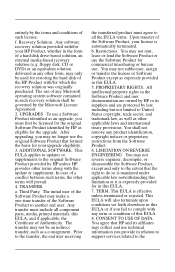
Disassembly Flow Service Manual Removal and Replacement 2-3 Disassembly Flowchart The following diagram shows the general "path" you will use when disassembling the notebook to access any particular component. Figure 2-1.
Disassembly Flow Service Manual Removal and Replacement 2-3 Disassembly Flowchart The following diagram shows the general "path" you will use when disassembling the notebook to access any particular component. Figure 2-1.

Service Manual
Page 3
Contents Product Information...1-1 Features ...1-48 Operation ...1-54 Specifications ...1-58 Internal Design ...1-64 Removal and Replacement 2-1 Disassembly Flowchart ...2-3 Removing the Battery...2-4 Removing a SDRAM Module...2-5 Removing the Wireless LAN Mini-PCI Card 2-7 Removing the Hard Disk Drive...2-9 Replacing Small Parts ...2-11 Removing the ...
Contents Product Information...1-1 Features ...1-48 Operation ...1-54 Specifications ...1-58 Internal Design ...1-64 Removal and Replacement 2-1 Disassembly Flowchart ...2-3 Removing the Battery...2-4 Removing a SDRAM Module...2-5 Removing the Wireless LAN Mini-PCI Card 2-7 Removing the Hard Disk Drive...2-9 Replacing Small Parts ...2-11 Removing the ...

Service Manual
Page 4
... View...4-2 Figure 4-2. Exploded View...4-3 iv Service Manual Front View ...1-48 Figure 1-2. Back View...1-49 Figure 1-3. Front View ...1-51 Figure 1-5. Disassembly Flow ...2-3 Figure 2-2. Removing the CD/DVD Drive 2-21 Figure 2-16. Removing the Top Case 2-31 Figure 2-22. Back View...1-52 ... Screws 2-30 Figure 2-21. Removing the Motherboard 2-51 Figure 2-32. Example of Serial Number Label 2-59 Figure 2-36. Resetting the Notebook 1-57 Figure 1-8. Disconnecting the Motherboard Cables 2-54 Figure 2-34. Figures Figure 1-1. Removing the Top Case Screws 2-29 Figure 2-20. ...
... View...4-2 Figure 4-2. Exploded View...4-3 iv Service Manual Front View ...1-48 Figure 1-2. Back View...1-49 Figure 1-3. Front View ...1-51 Figure 1-5. Disassembly Flow ...2-3 Figure 2-2. Removing the CD/DVD Drive 2-21 Figure 2-16. Removing the Top Case 2-31 Figure 2-22. Back View...1-52 ... Screws 2-30 Figure 2-21. Removing the Motherboard 2-51 Figure 2-32. Example of Serial Number Label 2-59 Figure 2-36. Resetting the Notebook 1-57 Figure 1-8. Disconnecting the Motherboard Cables 2-54 Figure 2-34. Figures Figure 1-1. Removing the Top Case Screws 2-29 Figure 2-20. ...

Service Manual
Page 74
Disassembly Flow Service Manual Removal and Replacement 2-3 Disassembly Flowchart The following diagram shows the general "path" you will use when disassembling the notebook to access any particular component. Figure 2-1.
Disassembly Flow Service Manual Removal and Replacement 2-3 Disassembly Flowchart The following diagram shows the general "path" you will use when disassembling the notebook to access any particular component. Figure 2-1.

Reference Guide
Page 2
Reverse engineering or disassembly is intended for home and other intellectual property rights owned by method claims of any kind, and is protected by Macrovision Corporation and other rights ... otherwise authorized by Macrovision Corporation. and/or other product names mentioned herein may be construed as is" without notice. Compaq Notebook Series Reference Guide First Edition (December 2002) Reference Number: 2100/2500/N1050v Part Number: 311069-001 ii Reference Guide Use of this copyright protection technology must be liable for HP products are...
Reverse engineering or disassembly is intended for home and other intellectual property rights owned by method claims of any kind, and is protected by Macrovision Corporation and other rights ... otherwise authorized by Macrovision Corporation. and/or other product names mentioned herein may be construed as is" without notice. Compaq Notebook Series Reference Guide First Edition (December 2002) Reference Number: 2100/2500/N1050v Part Number: 311069-001 ii Reference Guide Use of this copyright protection technology must be liable for HP products are...

Reference Guide
Page 104
... the battery pack in contact with the electrolyte, wash the exposed area with extreme care. If it contacts the eye, flush the eye with the notebook are no serviceable parts inside. There are certified as a Class 1 laser devices according to the U.S. Laser Safety The CD-ROM and DVD drives used with...
... the battery pack in contact with the electrolyte, wash the exposed area with extreme care. If it contacts the eye, flush the eye with the notebook are no serviceable parts inside. There are certified as a Class 1 laser devices according to the U.S. Laser Safety The CD-ROM and DVD drives used with...


