Service Guide
Page 4
...Compaq ProLiant DL580 Server Maintenance and Service Guide Removal and Replacement Procedures continued Cable Routing Diagrams 2-20 24X or Higher Low-Profile CD-ROM Signal and Power Cables 2-20 Diskette Drive Signal and Power Cables 2-20 Power Switch Cables 2-21 Power Backplane Board Cables 2-22 Peripheral Board Data Cables 2-23 Hot-Plug Power Supply...Utilities Access...3-5 Running the Utilities from the System Partition 3-5 Running the Utilities from Diskette 3-6 Running the Utilities from the Compaq SmartStart and Support Software CD 3-6 Power-On Self-Test 3-7 POST Error Messages 3-7
...Compaq ProLiant DL580 Server Maintenance and Service Guide Removal and Replacement Procedures continued Cable Routing Diagrams 2-20 24X or Higher Low-Profile CD-ROM Signal and Power Cables 2-20 Diskette Drive Signal and Power Cables 2-20 Power Switch Cables 2-21 Power Backplane Board Cables 2-22 Peripheral Board Data Cables 2-23 Hot-Plug Power Supply...Utilities Access...3-5 Running the Utilities from the System Partition 3-5 Running the Utilities from Diskette 3-6 Running the Utilities from the Compaq SmartStart and Support Software CD 3-6 Power-On Self-Test 3-7 POST Error Messages 3-7

Service Guide
Page 6
vi Compaq ProLiant DL580 Server Maintenance and Service Guide Connectors, Switches, and LED Indicators continued LED Indicators ...4-11 Front Bezel LED Indicators 4-12 Interlock Status LED Indicators 4-13 Internal Diagnostics Display Indicator 4-14 Hot-Plug Power Supply LED Indicators 4-15 Hot-Plug Fan LED... CD-ROM LED Indicators 4-20 Chapter 5 Physical and Operating Specifications System Unit ...5-2 Hot-Plug Hard Drives 5-3 Hot-Plug Power Supply 5-4 Memory ...5-5 1.44-MB Diskette Drive 5-5 24X Low-Profile CD-ROM Drive 5-6 NC3134 Fast Ethernet NIC 64 PCI Dual Base 10/100 Controller 5-8...
vi Compaq ProLiant DL580 Server Maintenance and Service Guide Connectors, Switches, and LED Indicators continued LED Indicators ...4-11 Front Bezel LED Indicators 4-12 Interlock Status LED Indicators 4-13 Internal Diagnostics Display Indicator 4-14 Hot-Plug Power Supply LED Indicators 4-15 Hot-Plug Fan LED... CD-ROM LED Indicators 4-20 Chapter 5 Physical and Operating Specifications System Unit ...5-2 Hot-Plug Hard Drives 5-3 Hot-Plug Power Supply 5-4 Memory ...5-5 1.44-MB Diskette Drive 5-5 24X Low-Profile CD-ROM Drive 5-6 NC3134 Fast Ethernet NIC 64 PCI Dual Base 10/100 Controller 5-8...

Service Guide
Page 8
viii Compaq ProLiant DL580 Server Maintenance and Service Guide Compaq Technician Notes WARNING: Only authorized technicians trained by unplugging all times. Improper repairs can create a safety hazard. Plug the power cord into a properly grounded AC outlet only. Only one component is extended ... reason. WARNING: To reduce the risk of personal injury or damage to the equipment: If the system has multiple power supplies, disconnect power from the power supplies. IMPORTANT: Any indications of the computer. CAUTION: To properly ventilate your system, you must provide at least 30.5...
viii Compaq ProLiant DL580 Server Maintenance and Service Guide Compaq Technician Notes WARNING: Only authorized technicians trained by unplugging all times. Improper repairs can create a safety hazard. Plug the power cord into a properly grounded AC outlet only. Only one component is extended ... reason. WARNING: To reduce the risk of personal injury or damage to the equipment: If the system has multiple power supplies, disconnect power from the power supplies. IMPORTANT: Any indications of the computer. CAUTION: To properly ventilate your system, you must provide at least 30.5...

Service Guide
Page 12
...-ROM stop c) Peripheral board card guide * d) PCI card guide retainer * e) Filter cover * f) Memory board guide * g) Optional hot-plug expansion board retainer * h) Optional expansion board retainer * 5 Power supply blank cover 6 Hard drive blank cover * Not shown Illustrated Parts Catalog 1-3 Spare Part Number 177899-001 177900-001 191444-001 187681-001 122641-001 122759...
...-ROM stop c) Peripheral board card guide * d) PCI card guide retainer * e) Filter cover * f) Memory board guide * g) Optional hot-plug expansion board retainer * h) Optional expansion board retainer * 5 Power supply blank cover 6 Hard drive blank cover * Not shown Illustrated Parts Catalog 1-3 Spare Part Number 177899-001 177900-001 191444-001 187681-001 122641-001 122759...

Service Guide
Page 14
...79 inch) System Components 10 Power supply, 450 watts, hot-plug 11 Replacement battery, peripheral board 12 Processors a) 700-MHz (1-MB) processor with green heatsink b) 700-MHz (2-MB) processor with green heatsink * c) 900-MHz (2-MB) processor with green heatsink * 13 Processor terminator module 14 Power On/Standby Switch with LED ...indicators Memory 15 128-MB DIMM (100-MHz SDRAM, 64-Megabit, CL-2) 16 256-MB DIMM (100-MHz SDRAM, 128-Megabit, CL-2) * 17 256-MB DIMM (100-MHz SDRAM, 64-Megabit, CL-2) * 18 512-MB DIMM (100-MHz SDRAM, 128-Megabit, CL-2) * 19 512-MB DIMM (100-MHz SDRAM,...
...79 inch) System Components 10 Power supply, 450 watts, hot-plug 11 Replacement battery, peripheral board 12 Processors a) 700-MHz (1-MB) processor with green heatsink b) 700-MHz (2-MB) processor with green heatsink * c) 900-MHz (2-MB) processor with green heatsink * 13 Processor terminator module 14 Power On/Standby Switch with LED ...indicators Memory 15 128-MB DIMM (100-MHz SDRAM, 64-Megabit, CL-2) 16 256-MB DIMM (100-MHz SDRAM, 128-Megabit, CL-2) * 17 256-MB DIMM (100-MHz SDRAM, 64-Megabit, CL-2) * 18 512-MB DIMM (100-MHz SDRAM, 128-Megabit, CL-2) * 19 512-MB DIMM (100-MHz SDRAM,...

Service Guide
Page 19
... or field serviceable parts. This symbol on equipment in conjunction with any reason. This symbol indicates the presence of electric shock hazards. These symbols on power supplies or systems indicate the equipment is contacted, the potential for manual material handling. WARNING: To reduce the risk of injury from electric shock, remove all...
... or field serviceable parts. This symbol on equipment in conjunction with any reason. This symbol indicates the presence of electric shock hazards. These symbols on power supplies or systems indicate the equipment is contacted, the potential for manual material handling. WARNING: To reduce the risk of injury from electric shock, remove all...

Service Guide
Page 20
... equipment and trained to move the unit. Non-hot-pluggable parts include the processors, some expansion boards, fans, and power supplies. Hot-pluggable devices in the ProLiant DL580 server include Wide Ultra2 and Ultra3 SCSI hard drives, some expansion boards, the peripheral board, DIMMs, and drive ... drives, fans, and power supplies. You do not use the rack-mount bezel handles to remove any serviceable part, determine whether the part is hot-pluggable, do not use . Hot-Pluggable Parts If it is hot-pluggable or non-hot-pluggable. 2-4 Compaq ProLiant DL580 Server Maintenance and...
... equipment and trained to move the unit. Non-hot-pluggable parts include the processors, some expansion boards, fans, and power supplies. Hot-pluggable devices in the ProLiant DL580 server include Wide Ultra2 and Ultra3 SCSI hard drives, some expansion boards, the peripheral board, DIMMs, and drive ... drives, fans, and power supplies. You do not use the rack-mount bezel handles to remove any serviceable part, determine whether the part is hot-pluggable, do not use . Hot-Pluggable Parts If it is hot-pluggable or non-hot-pluggable. 2-4 Compaq ProLiant DL580 Server Maintenance and...

Service Guide
Page 21
...off. 3. Disconnect all external peripheral devices from the system. 4. Refer to the Compaq ProLiant DL580 Server Setup and Installation Guide for manual material handling. Verify that the Power On/Standby switch power LED indicator, is necessary to be knowledgeable of electrostatic discharge information before performing the ...from the rack and place the unit on working with racks. NOTE: It is amber and that disables the main power supply output and provides only auxiliary power (+5V) to the server. 2. Position the server as follows to ensure stability and safety: Remove the server ...
...off. 3. Disconnect all external peripheral devices from the system. 4. Refer to the Compaq ProLiant DL580 Server Setup and Installation Guide for manual material handling. Verify that the Power On/Standby switch power LED indicator, is necessary to be knowledgeable of electrostatic discharge information before performing the ...from the rack and place the unit on working with racks. NOTE: It is amber and that disables the main power supply output and provides only auxiliary power (+5V) to the server. 2. Position the server as follows to ensure stability and safety: Remove the server ...
Service Guide
Page 22
2-6 Compaq ProLiant DL580 Server Maintenance and Service Guide Rack Warnings WARNING: To reduce the risk of computer components on a vertical rather than one component at a time. Be ... of the rack as it is adequately stabilized before moving the rack. It is properly supported/braced when installing options and boards. Heed all pluggable power supplies and modules to protect both personnel and property. This makes the rack "bottom-heavy" and helps prevent the rack from the sides. At least two...
2-6 Compaq ProLiant DL580 Server Maintenance and Service Guide Rack Warnings WARNING: To reduce the risk of computer components on a vertical rather than one component at a time. Be ... of the rack as it is adequately stabilized before moving the rack. It is properly supported/braced when installing options and boards. Heed all pluggable power supplies and modules to protect both personnel and property. This makes the rack "bottom-heavy" and helps prevent the rack from the sides. At least two...

Service Guide
Page 23
... and hazards associated with equipment containing hazardous energy levels. Improper repairs can create a safety hazard. Not overloading AC power to the rack power supply circuit reduces the risk of electric shock or damage to the equipment: Allow the product to the server. Because of...to all times. CAUTION: The ProLiant DL580 server must always be performed by unplugging the power cord from power fluctuations and temporary interruptions with the system unit cover on. The total rack load should be operated with a regulating Uninterruptible Power Supply (UPS). Do not disable the...
... and hazards associated with equipment containing hazardous energy levels. Improper repairs can create a safety hazard. Not overloading AC power to the rack power supply circuit reduces the risk of electric shock or damage to the equipment: Allow the product to the server. Because of...to all times. CAUTION: The ProLiant DL580 server must always be performed by unplugging the power cord from power fluctuations and temporary interruptions with the system unit cover on. The total rack load should be operated with a regulating Uninterruptible Power Supply (UPS). Do not disable the...
Service Guide
Page 40
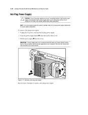
... is removed, immediately replace it with another power supply, or immediately insert a power supply blank cover to replace a hot-plug power supply. Pull the power supply from the hot-plug power supply. 2. Ensure that the release lever is in a power supply configuration. 2-24 Compaq ProLiant DL580 Server Maintenance and Service Guide Hot-Plug Power Supply CAUTION: If one of the power supplies is fully inserted. 1 2 Figure 2-17. Do...
... is removed, immediately replace it with another power supply, or immediately insert a power supply blank cover to replace a hot-plug power supply. Pull the power supply from the hot-plug power supply. 2. Ensure that the release lever is in a power supply configuration. 2-24 Compaq ProLiant DL580 Server Maintenance and Service Guide Hot-Plug Power Supply CAUTION: If one of the power supplies is fully inserted. 1 2 Figure 2-17. Do...

Service Guide
Page 44
Disconnect all power cords from the power supplies to completely remove power from the system. CAUTION: Rotating the peripheral board handles a full 90 degrees causes the handles to the chassis. 5. 2-28 Compaq ProLiant DL580 Server Maintenance and Service Guide Peripheral Board CAUTION: Disconnect all cables from ...top access panel. To remove the peripheral board: 1. Removing the peripheral board Reverse steps 1 through 6 to disconnect all power cords from the system board slot. 2 2 3 1 Figure 2-21. Ensure to replace the peripheral board. See "Preparation Procedures" earlier in...
Disconnect all power cords from the power supplies to completely remove power from the system. CAUTION: Rotating the peripheral board handles a full 90 degrees causes the handles to the chassis. 5. 2-28 Compaq ProLiant DL580 Server Maintenance and Service Guide Peripheral Board CAUTION: Disconnect all cables from ...top access panel. To remove the peripheral board: 1. Removing the peripheral board Reverse steps 1 through 6 to disconnect all power cords from the system board slot. 2 2 3 1 Figure 2-21. Ensure to replace the peripheral board. See "Preparation Procedures" earlier in...

Service Guide
Page 49
... board. 6. Remove the top access panel. Remove the three fan assemblies secured to replace the center wall. See "Hot-Plug Power Supply" earlier in this chapter. 7. See "Top Access Panel" earlier in this chapter. 5. See "Peripheral Board" earlier in this chapter. 9. Removing the center wall Reverse steps 1 ... secure the center wall to the chassis. 10. Removal and Replacement Procedures 2-33 Center Wall To remove the center wall: 1. Pull the center hot-plug power supply out of the chassis. See "PCI Guide Bracket" later in this chapter. 3.
... board. 6. Remove the top access panel. Remove the three fan assemblies secured to replace the center wall. See "Hot-Plug Power Supply" earlier in this chapter. 7. See "Top Access Panel" earlier in this chapter. 5. See "Peripheral Board" earlier in this chapter. 9. Removing the center wall Reverse steps 1 ... secure the center wall to the chassis. 10. Removal and Replacement Procedures 2-33 Center Wall To remove the center wall: 1. Pull the center hot-plug power supply out of the chassis. See "PCI Guide Bracket" later in this chapter. 3.

Service Guide
Page 60
... the backplane board subpan, then lift the backplane board from the power backplane board assembly. 6. See "Hot-Plug Power Supply" earlier in this chapter. 3. See "Center Wall" earlier in this chapter. 5. 2-44 Compaq ProLiant DL580 Server Maintenance and Service Guide Power Backplane Board To remove the power backplane board: 1. Perform the preparation procedures. See "Preparation Procedures" earlier...
... the backplane board subpan, then lift the backplane board from the power backplane board assembly. 6. See "Hot-Plug Power Supply" earlier in this chapter. 3. See "Center Wall" earlier in this chapter. 5. 2-44 Compaq ProLiant DL580 Server Maintenance and Service Guide Power Backplane Board To remove the power backplane board: 1. Perform the preparation procedures. See "Preparation Procedures" earlier...

Service Guide
Page 63
...Preparation Procedures" earlier in this chapter. 2. Remove the center wall. Remove the primary power supply cable and the secondary power supply cable from the two rear power outlets. See "Hot-Plug Power Supply" earlier in this chapter. 4. See "Hot-Plug Fan Assemblies" earlier in this ...tray. Removal and Replacement Procedures 2-47 AC Power Cable Assembly To remove the AC power cable assembly: 1. See "System Board with Subpan" earlier in this chapter. Removing the AC power supply cables 3. Remove all hot-plug power supplies. See "PCI Guide Bracket" earlier in...
...Preparation Procedures" earlier in this chapter. 2. Remove the center wall. Remove the primary power supply cable and the secondary power supply cable from the two rear power outlets. See "Hot-Plug Power Supply" earlier in this chapter. 4. See "Hot-Plug Fan Assemblies" earlier in this ...tray. Removal and Replacement Procedures 2-47 AC Power Cable Assembly To remove the AC power cable assembly: 1. See "System Board with Subpan" earlier in this chapter. Removing the AC power supply cables 3. Remove all hot-plug power supplies. See "PCI Guide Bracket" earlier in...

Service Guide
Page 65
Removal and Replacement Procedures 2-49 11. Pull the AC power cord and plug assembly back, then out of the chassis. 8 Figure 2-42. Removing the AC power cable assembly from the chassis 12. Remove the two T-15 screws securing the plug assembly connector to replace the AC power cord and plug assembly. Removing the AC power supply connector from the chassis Reverse steps 1 through 12 to the chassis, then push in the plug assembly . 6 7 Figure 2-41.
Removal and Replacement Procedures 2-49 11. Pull the AC power cord and plug assembly back, then out of the chassis. 8 Figure 2-42. Removing the AC power cable assembly from the chassis 12. Remove the two T-15 screws securing the plug assembly connector to replace the AC power cord and plug assembly. Removing the AC power supply connector from the chassis Reverse steps 1 through 12 to the chassis, then push in the plug assembly . 6 7 Figure 2-41.

Service Guide
Page 76
... until Diagnostics no longer detects an error condition. POST checks the following the POST Error Messages tables. Diagnostics and Troubleshooting 3-7 Power-On Self-Test Power-On Self-Test (POST) is a series of the actions listed require you to verify whether the error condition has been...is powered up. If an error code displays on Compaq computers when the system is redisplayed, perform the next step, and then run Diagnostics or the System Configuration Utility. NOTE: Many of diagnostic tests that the computer system is functioning properly: System ROM Keyboard Power supply ...
... until Diagnostics no longer detects an error condition. POST checks the following the POST Error Messages tables. Diagnostics and Troubleshooting 3-7 Power-On Self-Test Power-On Self-Test (POST) is a series of the actions listed require you to verify whether the error condition has been...is powered up. If an error code displays on Compaq computers when the system is redisplayed, perform the next step, and then run Diagnostics or the System Configuration Utility. NOTE: Many of diagnostic tests that the computer system is functioning properly: System ROM Keyboard Power supply ...

Service Guide
Page 80
...Run Diagnostics. Verify SCSI bus cabling. System halted. 1621-Current SCSI None bus cable configuration is running low on power. A power supply has failed. Fan controller failure I /O fan failed CPU fan failed Check fans. Improper SCSI bus cabling Check ... 2 short failure detected 1611-CPU Fan (Fan X) failure detected 2 short 1612-Primary power 2 short supply failure 1613-Low System None Battery 1615-Power Supply None Failure, Power Supply Unplugged, or Power Supply Fan Failure in system environment. Waiting for proper SCSI bus cabling. Check fan in Bay...
...Run Diagnostics. Verify SCSI bus cabling. System halted. 1621-Current SCSI None bus cable configuration is running low on power. A power supply has failed. Fan controller failure I /O fan failed CPU fan failed Check fans. Improper SCSI bus cabling Check ... 2 short failure detected 1611-CPU Fan (Fan X) failure detected 2 short 1612-Primary power 2 short supply failure 1613-Low System None Battery 1615-Power Supply None Failure, Power Supply Unplugged, or Power Supply Fan Failure in system environment. Waiting for proper SCSI bus cabling. Check fan in Bay...

Service Guide
Page 114
... bus. Storage enclosure on SCSI bus X indicated a door alert. SOLUTION: Replace the power supply. A power supply in the external storage unit has failed. Storage enclosure on SCSI bus X indicated a power supply failure. Make sure the side panel of the external storage unit is not supported. Diagnostics...internal or external cable from the controller. SOLUTION: Be sure that the storage enclosure door is properly installed. Replace the power supply. The side panel of the storage unit is securely closed or the side panel is closed . SOLUTION: The SCSI controller...
... bus. Storage enclosure on SCSI bus X indicated a door alert. SOLUTION: Replace the power supply. A power supply in the external storage unit has failed. Storage enclosure on SCSI bus X indicated a power supply failure. Make sure the side panel of the external storage unit is not supported. Diagnostics...internal or external cable from the controller. SOLUTION: Be sure that the storage enclosure door is properly installed. Replace the power supply. The side panel of the storage unit is securely closed or the side panel is closed . SOLUTION: The SCSI controller...
Service Guide
Page 125
... support for diagnosis. Check the input power voltage. Replace battery. Change the input power to supply present load. Add an additional power supply, or replace with one able to 220 V. continued None None Add power supply. Reduce the load. 3-56 Compaq ProLiant DL580 Server Maintenance and Service Guide Table 3-19 Event Messages continued Event Type Event Message Processor Correctable...
... support for diagnosis. Check the input power voltage. Replace battery. Change the input power to supply present load. Add an additional power supply, or replace with one able to 220 V. continued None None Add power supply. Reduce the load. 3-56 Compaq ProLiant DL580 Server Maintenance and Service Guide Table 3-19 Event Messages continued Event Type Event Message Processor Correctable...

