Maintenance and Service Guide
Page 6
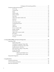
... procedures 41 Service tag ...41 Computer feet ...42 Battery ...43 WLAN module ...44 Memory module ...47 Hard drive ...48 Optical drive (select models only 51 Keyboard ...53 Top cover ...56 Power button board 60 TouchPad button board 61 Speakers ...63 USB board ...65 Power connector cable 66 Display assembly ...68 System...
... procedures 41 Service tag ...41 Computer feet ...42 Battery ...43 WLAN module ...44 Memory module ...47 Hard drive ...48 Optical drive (select models only 51 Keyboard ...53 Top cover ...56 Power button board 60 TouchPad button board 61 Speakers ...63 USB board ...65 Power connector cable 66 Display assembly ...68 System...
Maintenance and Service Guide
Page 16
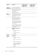
... support (3wire plug with multi-touch gestures, 2- √ finger scrolling, and pinch- Category Description Computer models equipped with an AMD processor Keyboard/ Full-size 14-in, textured, pocket, √ pointing devices keyboard with full numeric keypad TouchPad with ground pin, supports 3pin DC connector) Support for the following √ batteries: ● 6-cell...
... support (3wire plug with multi-touch gestures, 2- √ finger scrolling, and pinch- Category Description Computer models equipped with an AMD processor Keyboard/ Full-size 14-in, textured, pocket, √ pointing devices keyboard with full numeric keypad TouchPad with ground pin, supports 3pin DC connector) Support for the following √ batteries: ● 6-cell...

Maintenance and Service Guide
Page 29
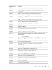
...spare part information, see Display assembly subcomponents on page 30 for more Plastics Kit spare part information. Computer major components 21 Keyboard (includes keyboard cable): For use in Brazil 646125-201 For use in Latin America 646125-161 For use in South Korea 646125-AD1...finish for use with all computer models: AntiGlare in pewter finish 646666-001 BrightView in pewter finish 646664-001 For use only with Compaq 435 and Compaq 436 computer models: AntiGlare in charcoal gray finish 647607-001 BrightView in , high definition (HD), light-emitting diode (LED), display ...
...spare part information, see Display assembly subcomponents on page 30 for more Plastics Kit spare part information. Computer major components 21 Keyboard (includes keyboard cable): For use in Brazil 646125-201 For use in Latin America 646125-161 For use in South Korea 646125-AD1...finish for use with all computer models: AntiGlare in pewter finish 646666-001 BrightView in pewter finish 646664-001 For use only with Compaq 435 and Compaq 436 computer models: AntiGlare in charcoal gray finish 647607-001 BrightView in , high definition (HD), light-emitting diode (LED), display ...
Maintenance and Service Guide
Page 41
...Plastics Kit spare part information. 14.0-in, HD, LED, BrightView display assembly in charcoal gray finish for use only with Compaq 435 and Compaq 436 models (includes webcam, microphone, and wireless antenna transceivers and cables) 14.0-in, HD, LED, BrightView display panel...(select models only) Keyboard for use in the United States (includes keyboard cable) Keyboard for use in Latin America (includes keyboard cable) Keyboard for use in Brazil (includes keyboard cable) Keyboard for use in Thailand (includes keyboard cable) Keyboard for use in South Korea (includes keyboard cable) RTC battery ...
...Plastics Kit spare part information. 14.0-in, HD, LED, BrightView display assembly in charcoal gray finish for use only with Compaq 435 and Compaq 436 models (includes webcam, microphone, and wireless antenna transceivers and cables) 14.0-in, HD, LED, BrightView display panel...(select models only) Keyboard for use in the United States (includes keyboard cable) Keyboard for use in Latin America (includes keyboard cable) Keyboard for use in Brazil (includes keyboard cable) Keyboard for use in Thailand (includes keyboard cable) Keyboard for use in South Korea (includes keyboard cable) RTC battery ...
Maintenance and Service Guide
Page 61
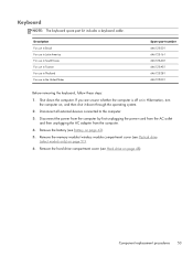
... the United States Spare part number 646125-201 646125-161 646125-AD1 646125-AB1 646125-281 646125-001 Before removing the keyboard, follow these steps: 1. Remove the memory module/wireless module compartment cover (see Battery on page 48). Component replacement... procedures 53 Disconnect all external devices connected to the computer. 3. Keyboard NOTE: The keyboard spare part kit includes a keyboard cable. Shut down through the operating system. 2. Remove the hard drive compartment cover (see Hard drive on ...
... the United States Spare part number 646125-201 646125-161 646125-AD1 646125-AB1 646125-281 646125-001 Before removing the keyboard, follow these steps: 1. Remove the memory module/wireless module compartment cover (see Battery on page 48). Component replacement... procedures 53 Disconnect all external devices connected to the computer. 3. Keyboard NOTE: The keyboard spare part kit includes a keyboard cable. Shut down through the operating system. 2. Remove the hard drive compartment cover (see Hard drive on ...
Maintenance and Service Guide
Page 62
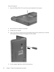
Insert a screw driver or similar thin tool into the keyboard release hole, and then press on its left side. 3. Remove the keyboard: 1. Turn the computer right-side up with the front toward you. 54 Chapter 4 Removal and replacement procedures Partially open the computer. 4. Remove the Phillips PM2.5×5.0 screw that secures the keyboard to the computer. 2. Rest and secure the computer on the back of the keyboard until the keyboard disengages from the computer. 5.
Insert a screw driver or similar thin tool into the keyboard release hole, and then press on its left side. 3. Remove the keyboard: 1. Turn the computer right-side up with the front toward you. 54 Chapter 4 Removal and replacement procedures Partially open the computer. 4. Remove the Phillips PM2.5×5.0 screw that secures the keyboard to the computer. 2. Rest and secure the computer on the back of the keyboard until the keyboard disengages from the computer. 5.
Maintenance and Service Guide
Page 63
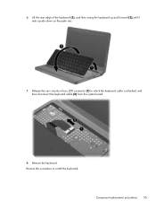
Remove the keyboard. Component replacement procedures 55 6. Release the zero insertion force (ZIF) connector (1) to install the keyboard. Reverse this procedure to which the keyboard cable is attached, and then disconnect the keyboard cable (2) from the system board. 8. Lift the rear edge of the keyboard (1), and then swing the keyboard up and forward (2) until it rests upside down on the palm rest. 7.
Remove the keyboard. Component replacement procedures 55 6. Release the zero insertion force (ZIF) connector (1) to install the keyboard. Reverse this procedure to which the keyboard cable is attached, and then disconnect the keyboard cable (2) from the system board. 8. Lift the rear edge of the keyboard (1), and then swing the keyboard up and forward (2) until it rests upside down on the palm rest. 7.

Maintenance and Service Guide
Page 64
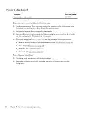
... Hard drive (see Hard drive on page 48) ● Keyboard (see TouchPad button board on , and then shut it down the computer. If you . 56 Chapter 4 Removal and replacement procedures Turn the computer upside down, with Compaq 435 and Compaq 436 computer models Spare part number 646667-001 645963-001 Before removing...top cover: ● Power button board and cable (see Power button board on page 60) ● TouchPad button board and cable (see Keyboard on page 53) NOTE: When replacing the top cover, be sure that the following components are unsure whether the computer is off or in ...
... Hard drive (see Hard drive on page 48) ● Keyboard (see TouchPad button board on , and then shut it down the computer. If you . 56 Chapter 4 Removal and replacement procedures Turn the computer upside down, with Compaq 435 and Compaq 436 computer models Spare part number 646667-001 645963-001 Before removing...top cover: ● Power button board and cable (see Power button board on page 60) ● TouchPad button board and cable (see Keyboard on page 53) NOTE: When replacing the top cover, be sure that the following components are unsure whether the computer is off or in ...
Maintenance and Service Guide
Page 68
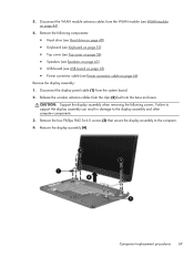
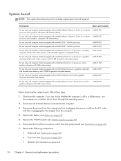
... components: ● Memory module/wireless module compartment cover (see WLAN module on page 44) ● Hard drive (see Hard drive on page 48) ● Keyboard (see Keyboard on page 53) ● Top cover (see Top cover on , and then shut it down the computer. Disconnect the power from the computer by first...
... components: ● Memory module/wireless module compartment cover (see WLAN module on page 44) ● Hard drive (see Hard drive on page 48) ● Keyboard (see Keyboard on page 53) ● Top cover (see Top cover on , and then shut it down the computer. Disconnect the power from the computer by first...
Maintenance and Service Guide
Page 69
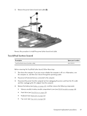
... components: ● Memory module/wireless module compartment cover (see WLAN module on page 44) ● Hard drive (see Hard drive on page 48) ● Keyboard (see Keyboard on page 53) ● Top cover (see Top cover on , and then shut it down the computer. Remove the power button board and cable (2). TouchPad...
... components: ● Memory module/wireless module compartment cover (see WLAN module on page 44) ● Hard drive (see Hard drive on page 48) ● Keyboard (see Keyboard on page 53) ● Top cover (see Top cover on , and then shut it down the computer. Remove the power button board and cable (2). TouchPad...
Maintenance and Service Guide
Page 71
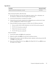
... components: ● Memory module/wireless module compartment cover (see WLAN module on page 44) ● Hard drive (see Hard drive on page 48) ● Keyboard (see Keyboard on page 53) ● Top cover (see Top cover on , and then shut it down the computer. Disconnect the speaker cable (1) from the clips built...
... components: ● Memory module/wireless module compartment cover (see WLAN module on page 44) ● Hard drive (see Hard drive on page 48) ● Keyboard (see Keyboard on page 53) ● Top cover (see Top cover on , and then shut it down the computer. Disconnect the speaker cable (1) from the clips built...
Maintenance and Service Guide
Page 73
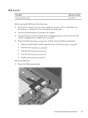
... following components: ● Memory module/wireless module compartment cover (see WLAN module on page 44) ● Hard drive (see Hard drive on page 48) ● Keyboard (see Keyboard on page 53) ● Top cover (see Top cover on page 56) ● Speakers (see Speakers on , and then shut it down the computer.
... following components: ● Memory module/wireless module compartment cover (see WLAN module on page 44) ● Hard drive (see Hard drive on page 48) ● Keyboard (see Keyboard on page 53) ● Top cover (see Top cover on page 56) ● Speakers (see Speakers on , and then shut it down the computer.
Maintenance and Service Guide
Page 74
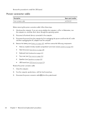
... following components: ● Memory module/wireless module compartment cover (see WLAN module on page 44) ● Hard drive (see Hard drive on page 48) ● Keyboard (see Keyboard on page 53) ● Top cover (see Top cover on page 56) ● Speakers (see Speakers on page 63) ● USB board (see USB...
... following components: ● Memory module/wireless module compartment cover (see WLAN module on page 44) ● Hard drive (see Hard drive on page 48) ● Keyboard (see Keyboard on page 53) ● Top cover (see Top cover on page 56) ● Speakers (see Speakers on page 63) ● USB board (see USB...
Maintenance and Service Guide
Page 77
... (2) built into the base enclosure. CAUTION: Support the display assembly when removing the following components: ● Hard drive (see Hard drive on page 48) ● Keyboard (see Keyboard on page 53) ● Top cover (see Top cover on page 56) ● Speakers (see Speakers on page 63) ● USB board (see USB...
... (2) built into the base enclosure. CAUTION: Support the display assembly when removing the following components: ● Hard drive (see Hard drive on page 48) ● Keyboard (see Keyboard on page 53) ● Top cover (see Top cover on page 56) ● Speakers (see Speakers on page 63) ● USB board (see USB...
Maintenance and Service Guide
Page 84
Remove the following components: ● Keyboard (see Keyboard on page 53) ● Top cover (see Top cover on page 56) ● Speakers (see Battery on page 43). 5. If you are unsure whether the ...
Remove the following components: ● Keyboard (see Keyboard on page 53) ● Top cover (see Top cover on page 56) ● Speakers (see Battery on page 43). 5. If you are unsure whether the ...
Maintenance and Service Guide
Page 87
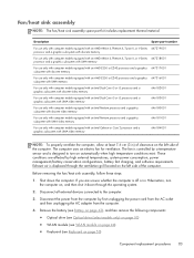
... steps: 1. Remove the battery (see Battery on page 43), and then remove the following components: ● WLAN module (see WLAN module on page 44) ● Keyboard (see Keyboard on page 53) ● Top cover (see Top cover on page 56) ● Speakers (see Speakers on page 63) ● USB board (see USB...
... steps: 1. Remove the battery (see Battery on page 43), and then remove the following components: ● WLAN module (see WLAN module on page 44) ● Keyboard (see Keyboard on page 53) ● Top cover (see Top cover on page 56) ● Speakers (see Speakers on page 63) ● USB board (see USB...
Maintenance and Service Guide
Page 89
... computer. 4. Remove the battery (see Battery on page 43), and then remove the following components: ● WLAN module (see WLAN module on page 44) ● Keyboard (see Keyboard on page 53) ● Top cover (see Top cover on page 56) ● Speakers (see Speakers on page 63) ● USB board (see USB...
... computer. 4. Remove the battery (see Battery on page 43), and then remove the following components: ● WLAN module (see WLAN module on page 44) ● Keyboard (see Keyboard on page 53) ● Top cover (see Top cover on page 56) ● Speakers (see Speakers on page 63) ● USB board (see USB...
Maintenance and Service Guide
Page 91
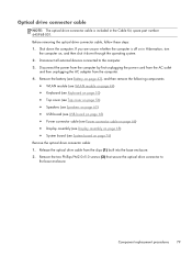
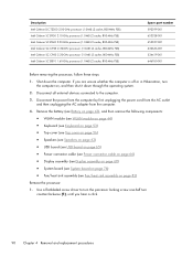
... following components: ● Optical drive (see Optical drive (select models only) on page 51) ● WLAN module (see WLAN module on page 44) ● Keyboard (see Keyboard on the left side of clearance on page 53) Component replacement procedures 83 Description Spare part number For use only with computer models equipped with...
... following components: ● Optical drive (see Optical drive (select models only) on page 51) ● WLAN module (see WLAN module on page 44) ● Keyboard (see Keyboard on the left side of clearance on page 53) Component replacement procedures 83 Description Spare part number For use only with computer models equipped with...
Maintenance and Service Guide
Page 98
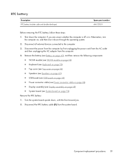
... system. 2. Remove the battery (see Battery on page 43), and then remove the following components: ● WLAN module (see WLAN module on page 44) ● Keyboard (see Keyboard on page 53) ● Top cover (see Top cover on page 56) ● Speakers (see Speakers on page 63) ● USB board (see USB...
... system. 2. Remove the battery (see Battery on page 43), and then remove the following components: ● WLAN module (see WLAN module on page 44) ● Keyboard (see Keyboard on page 53) ● Top cover (see Top cover on page 56) ● Speakers (see Speakers on page 63) ● USB board (see USB...
Maintenance and Service Guide
Page 100
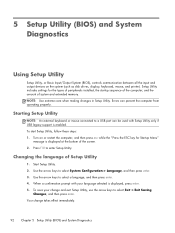
...to enter Setup Utility. NOTE: Use extreme care when making changes in Setup Utility. Turn on the system (such as disk drives, display, keyboard, mouse, and printer). Changing the language of Setup Utility 1. Errors can be used with your change takes effect immediately. 92 Chapter 5 ...press enter. 3. Use the arrow keys to select Exit > Exit Saving Changes, and then press enter. Starting Setup Utility NOTE: An external keyboard or mouse connected to a USB port can prevent the computer from operating properly. Start Setup Utility. 2. Your change and exit Setup Utility, use...
...to enter Setup Utility. NOTE: Use extreme care when making changes in Setup Utility. Turn on the system (such as disk drives, display, keyboard, mouse, and printer). Changing the language of Setup Utility 1. Errors can be used with your change takes effect immediately. 92 Chapter 5 ...press enter. 3. Use the arrow keys to select Exit > Exit Saving Changes, and then press enter. Starting Setup Utility NOTE: An external keyboard or mouse connected to a USB port can prevent the computer from operating properly. Start Setup Utility. 2. Your change and exit Setup Utility, use...


