Software Guide
Page 17
...01 Configuring a Login Banner 27-4 Clearing the Login Banner 27-5 Enabling or Disabling the "Cisco Systems Console" Telnet Login Banner 27-5 Defining and Using Command Aliases 27-6 Defining and ...Power Management 28-1 Understanding How Power Management Works on the Catalyst 4500 Series Switches 28-1 Power Management Overview 28-2 Understanding Power Management Modes 28-2 Available Power for Power Supplies 28-4 Power Management Limitations 28-4 1400 W DC Power Supply Guidelines and Restrictions 28-5 Understanding How Power Management Works on the Catalyst 4006 Switch 28-6 Understanding Power...
...01 Configuring a Login Banner 27-4 Clearing the Login Banner 27-5 Enabling or Disabling the "Cisco Systems Console" Telnet Login Banner 27-5 Defining and Using Command Aliases 27-6 Defining and ...Power Management 28-1 Understanding How Power Management Works on the Catalyst 4500 Series Switches 28-1 Power Management Overview 28-2 Understanding Power Management Modes 28-2 Available Power for Power Supplies 28-4 Power Management Limitations 28-4 1400 W DC Power Supply Guidelines and Restrictions 28-5 Understanding How Power Management Works on the Catalyst 4006 Switch 28-6 Understanding Power...
Software Guide
Page 31
... series switches. Table 1-1 Catalyst 4000 Series and Catalyst 4500 Series Switches Product Number Catalyst 4000 Series WS-C4003 WS-C4006 Chassis Description Catalyst 4003 • Modular 3-slot chassis • Optional redundant power supplies Catalyst 4006 • Modular 6-slot chassis • 30-Gbps backplane • Two power supplies with optional third power supply 78-15486-01 Catalyst 4500 Series, Catalyst 2948G, Catalyst 2980G Switches Software Configuration Guide-Release 8.1 1-1 These switches provide switched...
... series switches. Table 1-1 Catalyst 4000 Series and Catalyst 4500 Series Switches Product Number Catalyst 4000 Series WS-C4003 WS-C4006 Chassis Description Catalyst 4003 • Modular 3-slot chassis • Optional redundant power supplies Catalyst 4006 • Modular 6-slot chassis • 30-Gbps backplane • Two power supplies with optional third power supply 78-15486-01 Catalyst 4500 Series, Catalyst 2948G, Catalyst 2980G Switches Software Configuration Guide-Release 8.1 1-1 These switches provide switched...
Software Guide
Page 32
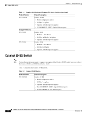
... Gbps full duplex • Optional redundant power supplies Catalyst 2948G Switch Note For installation information and a complete description of the Catalyst 2948G switch hardware, refer to the Catalyst 2948G and 2980G Installation Guide. Table 1-2 Catalyst 2948G Switch Product Number WS-C2948G Chassis Description Catalyst 2948G • Fixed-configuration switch • 12-Gbps backplane • Optional redundant power supplies • Two 1000BASE-X (GBIC) Gigabit Ethernet...
... Gbps full duplex • Optional redundant power supplies Catalyst 2948G Switch Note For installation information and a complete description of the Catalyst 2948G switch hardware, refer to the Catalyst 2948G and 2980G Installation Guide. Table 1-2 Catalyst 2948G Switch Product Number WS-C2948G Chassis Description Catalyst 2948G • Fixed-configuration switch • 12-Gbps backplane • Optional redundant power supplies • Two 1000BASE-X (GBIC) Gigabit Ethernet...

Software Guide
Page 33
Some modules require an additional software image, which you can configure modules and ports on the switches. Table 1-3 Catalyst 2980G Switch Product Number WS-C2980G-A Chassis Description Catalyst 2980G • Fixed-configuration switch • 12-Gbps backplane • Optional redundant power supplies • Two 1000BASE-X (GBIC) Gigabit Ethernet ports • 80 10/100BASE-TX Fast Ethernet ports Supervisor Engine...
Some modules require an additional software image, which you can configure modules and ports on the switches. Table 1-3 Catalyst 2980G Switch Product Number WS-C2980G-A Chassis Description Catalyst 2980G • Fixed-configuration switch • 12-Gbps backplane • Optional redundant power supplies • Two 1000BASE-X (GBIC) Gigabit Ethernet ports • 80 10/100BASE-TX Fast Ethernet ports Supervisor Engine...
Software Guide
Page 373
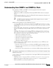
...software (see Chapter 25, "Configuring RMON") • RMON and RMON2 on an external SwitchProbe device 78-15486-01 Catalyst 4500 Series, Catalyst 2948G, Catalyst 2980G Switches Software Configuration Guide-Release 8.1 24-5 When there are managed devices that is called a network management system (NMS)....SNMPv1 and SNMPv2c Work Understanding How SNMPv1 and SNMPv2c Work The components of the three community string definitions on the switch. When power supply errors occur • SNMP community strings-SNMP community strings authenticate access to all objects in MIB, including community ...
...software (see Chapter 25, "Configuring RMON") • RMON and RMON2 on an external SwitchProbe device 78-15486-01 Catalyst 4500 Series, Catalyst 2948G, Catalyst 2980G Switches Software Configuration Guide-Release 8.1 24-5 When there are managed devices that is called a network management system (NMS)....SNMPv1 and SNMPv2c Work Understanding How SNMPv1 and SNMPv2c Work The components of the three community string definitions on the switch. When power supply errors occur • SNMP community strings-SNMP community strings authenticate access to all objects in MIB, including community ...

Software Guide
Page 412
...ending delimiter, press Return. Configuring a Login Banner To configure a login banner, perform this task in to the switch. Display the login banner by logging out and logging back in privileged mode: Step 1 Step 2 Task Set the...Catalyst 4500 Series, Catalyst 2948G, Catalyst 2980G Switches Software Configuration Guide-Release 8.1 78-15486-01 Command set the system clock, perform this task in to the switch. Setting the System Clock Chapter 27 Administering the Switch disable 9600 0% 0% Wed Apr 24 2002, 15:46:01 Power Capacity of the Chassis:2 supplies WARNING:Power supplies...
...ending delimiter, press Return. Configuring a Login Banner To configure a login banner, perform this task in to the switch. Display the login banner by logging out and logging back in privileged mode: Step 1 Step 2 Task Set the...Catalyst 4500 Series, Catalyst 2948G, Catalyst 2980G Switches Software Configuration Guide-Release 8.1 78-15486-01 Command set the system clock, perform this task in to the switch. Setting the System Clock Chapter 27 Administering the Switch disable 9600 0% 0% Wed Apr 24 2002, 15:46:01 Power Capacity of the Chassis:2 supplies WARNING:Power supplies...

Software Guide
Page 422
... switching modules. 28-2 Catalyst 4500 Series, Catalyst 2948G, Catalyst 2980G Switches Software Configuration Guide-Release 8.1 78-15486-01 Your switch hardware configuration dictates which power supply or supplies you use the combined mode. Combined mode has no power redundancy. A single power supply must have enough power to support the switch configuration. Your switch will not have power redundancy. if a power supply fails, one power supply as a primary power supply and the second power supply...
... switching modules. 28-2 Catalyst 4500 Series, Catalyst 2948G, Catalyst 2980G Switches Software Configuration Guide-Release 8.1 78-15486-01 Your switch hardware configuration dictates which power supply or supplies you use the combined mode. Combined mode has no power redundancy. A single power supply must have enough power to support the switch configuration. Your switch will not have power redundancy. if a power supply fails, one power supply as a primary power supply and the second power supply...

Software Guide
Page 423
... power supplies with different types or wattages in your switch, the switch uses the power supply in power supply bay 1 (PS1) and ignores the power supply in power supply bay (PS2). The total power available is not the mathematical sum of the maximum available power for chassis and inline power for each power supply. 78-15486-01 Catalyst 4500 Series, Catalyst 2948G, Catalyst 2980G Switches Software Configuration Guide-Release 8.1 28-3 Variable power supplies...
... power supplies with different types or wattages in your switch, the switch uses the power supply in power supply bay 1 (PS1) and ignores the power supply in power supply bay (PS2). The total power available is not the mathematical sum of the maximum available power for chassis and inline power for each power supply. 78-15486-01 Catalyst 4500 Series, Catalyst 2948G, Catalyst 2980G Switches Software Configuration Guide-Release 8.1 28-3 Variable power supplies...

Software Guide
Page 424
... by the supervisor engine(s), the fan trays, and the installed modules (including the inline power). Understanding How Power Management Works on the Catalyst 4500 Series Switches Chapter 28 Power Management Available Power for Power Supplies Table 28-1 lists the power that is provided by the power supplies for the supervisor engine(s), all line cards, and the fan tray. 2. The 1400 W DC...
... by the supervisor engine(s), the fan trays, and the installed modules (including the inline power). Understanding How Power Management Works on the Catalyst 4500 Series Switches Chapter 28 Power Management Available Power for Power Supplies Table 28-1 lists the power that is provided by the power supplies for the supervisor engine(s), all line cards, and the fan tray. 2. The 1400 W DC...

Software Guide
Page 425
... switch. • The 1400 W DC power supply works with your power supply for modules, backplane, and fans) and inline power. Chapter 28 Power Management Understanding How Power Management Works on the Catalyst 4500 Series Switches • Combined mode requires that you install two power supplies in redundant mode. • The 1400 W DC power supply has a separate power on the switch again, one power supply, and you set the switch...
... switch. • The 1400 W DC power supply works with your power supply for modules, backplane, and fans) and inline power. Chapter 28 Power Management Understanding How Power Management Works on the Catalyst 4500 Series Switches • Combined mode requires that you install two power supplies in redundant mode. • The 1400 W DC power supply has a separate power on the switch again, one power supply, and you set the switch...

Software Guide
Page 426
... Catalyst 4006 chassis with a WS-X4013 supervisor engine with only two power supplies by the power supply. You can set the power redundancy to two primary plus one redundant power supply (2+1 redundancy mode) or to leave one slot of the system. In those configurations, redundancy requires three power supplies. Understanding How Power Management Works on the Catalyst 4006 Switch Chapter 28 Power Management Understanding How Power...
... Catalyst 4006 chassis with a WS-X4013 supervisor engine with only two power supplies by the power supply. You can set the power redundancy to two primary plus one redundant power supply (2+1 redundancy mode) or to leave one slot of the system. In those configurations, redundancy requires three power supplies. Understanding How Power Management Works on the Catalyst 4006 Switch Chapter 28 Power Management Understanding How Power...

Software Guide
Page 427
... a chassis that has been operating in the Catalyst 4006 switch: • To compute the power requirements and verify that require more power than a single power supply can handle, the switch displays this message: Module has been inserted and Insufficient power supplies operating. In the 1+1 redundancy mode, the nonredundant power that require more power than is available, are installed in the show...
... a chassis that has been operating in the Catalyst 4006 switch: • To compute the power requirements and verify that require more power than a single power supply can handle, the switch displays this message: Module has been inserted and Insufficient power supplies operating. In the 1+1 redundancy mode, the nonredundant power that require more power than is available, are installed in the show...

Software Guide
Page 428
..., thus disrupting network connectivity. If the power requirement of 395 W: • WS-X4013 supervisor engine-110 W • Four WS-X4148-RJ modules-65 W each (180 W total) • Fan tray-25 W The following configuration requires more power than a single 400 W power supply can use a 400 W power supply and a 650 W power supply in your Catalyst 4006 switch and you use the available 650 W. It...
..., thus disrupting network connectivity. If the power requirement of 395 W: • WS-X4013 supervisor engine-110 W • Four WS-X4148-RJ modules-65 W each (180 W total) • Fan tray-25 W The following configuration requires more power than a single 400 W power supply can use a 400 W power supply and a 650 W power supply in your Catalyst 4006 switch and you use the available 650 W. It...

Software Guide
Page 431
... disable the detection mechanism. Note For information on the circuit. If there is 100 percent efficient. Table 28-3 Switch Components Supporting Inline Power Switch Chassis Catalyst 4006 Catalyst 4503 Catalyst 4506 Modules WS-X4148-RJ45V WS-X4148-RJ45V Power Supplies Catalyst 4000 Series Power Entry Module (PEM) 1300 W AC 2800 W AC 1400 W DC You can set each port; you must connect the...
... disable the detection mechanism. Note For information on the circuit. If there is 100 percent efficient. Table 28-3 Switch Components Supporting Inline Power Switch Chassis Catalyst 4006 Catalyst 4503 Catalyst 4506 Modules WS-X4148-RJ45V WS-X4148-RJ45V Power Supplies Catalyst 4000 Series Power Entry Module (PEM) 1300 W AC 2800 W AC 1400 W DC You can set each port; you must connect the...
Software Guide
Page 435
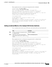
... Power supplies are configured for 2500Watts DC input Power Budget is : 1 supply Power Available to the System (excluding voice power): 1000 Watts (83.33 Amps @12V) Power Drawn from the System (excluding voice power): 516 Watts (43.00 Amps @12V) Remaining Power (excluding voice power): 484 Watts (40.33 Amps @12V) Console>(enable) Setting Combined Mode on the Catalyst 4500 Series Switches...
... Power supplies are configured for 2500Watts DC input Power Budget is : 1 supply Power Available to the System (excluding voice power): 1000 Watts (83.33 Amps @12V) Power Drawn from the System (excluding voice power): 516 Watts (43.00 Amps @12V) Remaining Power (excluding voice power): 484 Watts (40.33 Amps @12V) Console>(enable) Setting Combined Mode on the Catalyst 4500 Series Switches...

Software Guide
Page 436
... input wattage for the 1400 W DC power supply. Configuring Power Management Chapter 28 Power Management Setting the DC Power Input To set the power budget for the Catalyst 4006 switch, perform this task in privileged mode: Step 1 Step 2 Task Set the power budget for the Catalyst 4006 switch. Command set power budget {1 | 2} show enviroment power Total Inline Power Available: 4166.00 Watts (83.32...
... input wattage for the 1400 W DC power supply. Configuring Power Management Chapter 28 Power Management Setting the DC Power Input To set the power budget for the Catalyst 4006 switch, perform this task in privileged mode: Step 1 Step 2 Task Set the power budget for the Catalyst 4006 switch. Command set power budget {1 | 2} show enviroment power Total Inline Power Available: 4166.00 Watts (83.32...

Software Guide
Page 437
... 0% 0% Fri May 31 2002, 10:24:04 Power Capacity of the Chassis: 1 supply 78-15486-01 Catalyst 4500 Series, Catalyst 2948G, Catalyst 2980G Switches Software Configuration Guide-Release 8.1 28-17 Command show system This example shows how to display the output for the switch: Console> (enable) set power budget 1 Warning: Your power supply budget will be constrained to the System...
... 0% 0% Fri May 31 2002, 10:24:04 Power Capacity of the Chassis: 1 supply 78-15486-01 Catalyst 4500 Series, Catalyst 2948G, Catalyst 2980G Switches Software Configuration Guide-Release 8.1 28-17 Command show system This example shows how to display the output for the switch: Console> (enable) set power budget 1 Warning: Your power supply budget will be constrained to the System...
Software Guide
Page 438
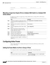
... to configure inline power for the Catalyst 4500 series switches and the Catalyst 4006 switch. Setting the Power Mode of a Port or Group of Ports To set the power budget to 1. configure bootflash:switch.cfg If you have only one power supply in your supervisor engine from the Catalyst 4006 switch and insert it into the Catalyst 4500 series switch. Configuring Inline Power These sections...
... to configure inline power for the Catalyst 4500 series switches and the Catalyst 4006 switch. Setting the Power Mode of a Port or Group of Ports To set the power budget to 1. configure bootflash:switch.cfg If you have only one power supply in your supervisor engine from the Catalyst 4006 switch and insert it into the Catalyst 4500 series switch. Configuring Inline Power These sections...

Software Guide
Page 441
... releases for IEEE 802.3af compliance • Cisco CallManager release 3.0 or later releases • If you want to configure Voice-over-IP (VoIP) for the Catalyst 4500 series switches. Table 29-1 Catalyst 4500 Series Components Supporting Inline Power Switch Chassis Catalyst 4006 Catalyst 4503 Catalyst 4506 Modules WS-X4148-RJ45V1 WS-X4148-RJ45V Power Supplies Catalyst 4000 Family Power Entry Module (PEM) 1300 W AC 2800...
... releases for IEEE 802.3af compliance • Cisco CallManager release 3.0 or later releases • If you want to configure Voice-over-IP (VoIP) for the Catalyst 4500 series switches. Table 29-1 Catalyst 4500 Series Components Supporting Inline Power Switch Chassis Catalyst 4006 Catalyst 4503 Catalyst 4506 Modules WS-X4148-RJ45V1 WS-X4148-RJ45V Power Supplies Catalyst 4000 Family Power Entry Module (PEM) 1300 W AC 2800...

Software Guide
Page 593
...; INDEX Numerics 10/100 port speed, setting 4-4 1400W DC power supply 28-5 802.1Q example 11-9, 11-19 mapping VLANs to ISL 10-11 overview 11-1 restrictions 11-4 supported switches (table) 11-3 802.1x authentication authentication server defined 31-2 client...auxiliary VLANs configuring 10-13 dynamic VLAN membership 12-14 software support 10-5 B BackboneFast adding a switch (figure) 8-7 78-15486-01 Catalyst 4500 Series, Catalyst 2948G, Catalyst 2980G Switches Software Configuration Guide-Release 8.1 IN-1 TACACS+ accounting adding multicast filter profiles 15-20 addresses See IP...
...; INDEX Numerics 10/100 port speed, setting 4-4 1400W DC power supply 28-5 802.1Q example 11-9, 11-19 mapping VLANs to ISL 10-11 overview 11-1 restrictions 11-4 supported switches (table) 11-3 802.1x authentication authentication server defined 31-2 client...auxiliary VLANs configuring 10-13 dynamic VLAN membership 12-14 software support 10-5 B BackboneFast adding a switch (figure) 8-7 78-15486-01 Catalyst 4500 Series, Catalyst 2948G, Catalyst 2980G Switches Software Configuration Guide-Release 8.1 IN-1 TACACS+ accounting adding multicast filter profiles 15-20 addresses See IP...

