
Hardware Installation Guide
Page 3
... i-viii Obtaining Documentation and Submitting a Service Request i-ix Product Overview 1-1 Setting Up the Switch 1-1 Features 1-1 Front Panel Description 1-3 Fast Ethernet Switch Front Panel Descriptions 1-3 Gigabit Ethernet Switch Front Panel Descriptions 1-6 10/100 and 10/100/1000 Ports 1-8 PoE Ports 1-9 SFP ...Purpose Port LEDs 1-15 Cable Guard 1-15 Rear Panel Description 1-15 Internal Power Supply 1-18 DC Power Connector 1-18 Cisco RPS 1-19 Cisco RPS 2300 1-19 Cisco RPS 675 1-19 Console Port 1-19 Security Slots 1-20 Management Options 1-20 Catalyst 3560 Switch Hardware Installation Guide iii
... i-viii Obtaining Documentation and Submitting a Service Request i-ix Product Overview 1-1 Setting Up the Switch 1-1 Features 1-1 Front Panel Description 1-3 Fast Ethernet Switch Front Panel Descriptions 1-3 Gigabit Ethernet Switch Front Panel Descriptions 1-6 10/100 and 10/100/1000 Ports 1-8 PoE Ports 1-9 SFP ...Purpose Port LEDs 1-15 Cable Guard 1-15 Rear Panel Description 1-15 Internal Power Supply 1-18 DC Power Connector 1-18 Cisco RPS 1-19 Cisco RPS 2300 1-19 Cisco RPS 675 1-19 Console Port 1-19 Security Slots 1-20 Management Options 1-20 Catalyst 3560 Switch Hardware Installation Guide iii

Hardware Installation Guide
Page 4
...the Switch on a Wall 2-14 Table- and 48-Port Switches) 2-1 Preparing for Installation 2-1 Warnings 2-2 Installation Guidelines 2-5 Box Contents 2-6 Tools and Equipment 2-6 Verifying Switch Operation 2-6 Powering Off the Switch 2-7 Installing the Switch ...Switch to Compatible Devices 2-20 Connecting to 10BASE-T or 100BASE-TX Devices 2-20 Connecting to Fiber-Optic SFP Modules 2-21 Connecting to 1000BASE-T SFP Modules 2-22 Connecting to a Dual-Purpose Port 2-23 Where to the Switch for Installation 3-1 Warnings 3-2 Installation Guidelines 3-5 Equipment That You Supply 3-6 Catalyst 3560 Switch...
...the Switch on a Wall 2-14 Table- and 48-Port Switches) 2-1 Preparing for Installation 2-1 Warnings 2-2 Installation Guidelines 2-5 Box Contents 2-6 Tools and Equipment 2-6 Verifying Switch Operation 2-6 Powering Off the Switch 2-7 Installing the Switch ...Switch to Compatible Devices 2-20 Connecting to 10BASE-T or 100BASE-TX Devices 2-20 Connecting to Fiber-Optic SFP Modules 2-21 Connecting to 1000BASE-T SFP Modules 2-22 Connecting to a Dual-Purpose Port 2-23 Where to the Switch for Installation 3-1 Warnings 3-2 Installation Guidelines 3-5 Equipment That You Supply 3-6 Catalyst 3560 Switch...

Hardware Installation Guide
Page 11
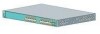
... Panel Description, page 1-15 • Management Options, page 1-20 Setting Up the Switch See the Catalyst 3560 Switch Getting Started Guide for instructions on AC power and supplies backup DC power to the switches. See the switch software configuration guide for an optional Cisco RPS 2300 or Cisco RPS 675 that operates on how to use Express Setup to initially...
... Panel Description, page 1-15 • Management Options, page 1-20 Setting Up the Switch See the Catalyst 3560 Switch Getting Started Guide for instructions on AC power and supplies backup DC power to the switches. See the switch software configuration guide for an optional Cisco RPS 2300 or Cisco RPS 675 that operates on how to use Express Setup to initially...
Hardware Installation Guide
Page 22
...properly connected. The internal power supply in a fault condition. For more information about the Cisco RPS 2300 and the RPS 675, see the Cisco Redundant Power System 2300 Hardware Installation Guide and the Cisco RPS 675 Redundant Power System Hardware Installation Guide. 1-12 Catalyst 3560 Switch Hardware Installation Guide OL-6337...does not, the RPS fan might have an RPS LED. Contact Cisco. If it is connected and ready to provide back-up power, if required. Note The Catalyst 3560-8PC and Catalyst 3560-12PC-S switches do not have failed. Press the Standby/Active button on the RPS...
...properly connected. The internal power supply in a fault condition. For more information about the Cisco RPS 2300 and the RPS 675, see the Cisco Redundant Power System 2300 Hardware Installation Guide and the Cisco RPS 675 Redundant Power System Hardware Installation Guide. 1-12 Catalyst 3560 Switch Hardware Installation Guide OL-6337...does not, the RPS fan might have an RPS LED. Contact Cisco. If it is connected and ready to provide back-up power, if required. Note The Catalyst 3560-8PC and Catalyst 3560-12PC-S switches do not have failed. Press the Standby/Active button on the RPS...
Hardware Installation Guide
Page 25
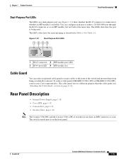
... from being used. Rear Panel Description • Internal Power Supply, page 1-18 • Cisco RPS, page 1-19 • Console Port, page 1-19 • Security Slots, page 1-20 Note The Catalyst 3560-8PC and the Catalyst 3560-12PC-S switches do not have the same meaning as an SFP module...not both at the same time. OL-6337-07 Catalyst 3560 Switch Hardware Installation Guide 1-15 The switch console port is on page 2-11). To order a cable guard (CBLGRD-C3560-12PC or CBLGRD-C3560-8PC), contact your Cisco representative. Chapter 1 Product Overview Rear Panel Description Dual-...
... from being used. Rear Panel Description • Internal Power Supply, page 1-18 • Cisco RPS, page 1-19 • Console Port, page 1-19 • Security Slots, page 1-20 Note The Catalyst 3560-8PC and the Catalyst 3560-12PC-S switches do not have the same meaning as an SFP module...not both at the same time. OL-6337-07 Catalyst 3560 Switch Hardware Installation Guide 1-15 The switch console port is on page 2-11). To order a cable guard (CBLGRD-C3560-12PC or CBLGRD-C3560-8PC), contact your Cisco representative. Chapter 1 Product Overview Rear Panel Description Dual-...
Hardware Installation Guide
Page 28
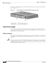
... 1-18 Catalyst 3560-8PC and Catalyst 3560-12PC-S Switch Rear Panel 250607 1 2 1 Heat sinks 2 AC power connector Internal Power Supply An internal power supply powers the switch. If the supply voltage is an autoranging unit that supports input voltages between 100 and 240 VAC. Caution You must connect the Catalyst 3560V2-24TS-SD switch only to -72 VDC. DC Power Connector The Catalyst 3560V2-24TS-SD has...
... 1-18 Catalyst 3560-8PC and Catalyst 3560-12PC-S Switch Rear Panel 250607 1 2 1 Heat sinks 2 AC power connector Internal Power Supply An internal power supply powers the switch. If the supply voltage is an autoranging unit that supports input voltages between 100 and 240 VAC. Caution You must connect the Catalyst 3560V2-24TS-SD switch only to -72 VDC. DC Power Connector The Catalyst 3560V2-24TS-SD has...

Hardware Installation Guide
Page 29
... connector cable supplied with the RPS to connect the RPS to -DB-25 female DTE adapter. Note When an RPS is connected to the Catalyst 3560V2-24TS-SD switch, the switch is a redundant power system that supports six network devices and provides power to a PC by means of network traffic. The maximum output power depends on Cisco.com: http...
... connector cable supplied with the RPS to connect the RPS to -DB-25 female DTE adapter. Note When an RPS is connected to the Catalyst 3560V2-24TS-SD switch, the switch is a redundant power system that supports six network devices and provides power to a PC by means of network traffic. The maximum output power depends on Cisco.com: http...

Hardware Installation Guide
Page 36
... might have more than one power supply connection. Statement 1040 Warning For connections outside the building where the equipment is available. Avoid using uninsulated exposed metal contacts, conductors, or terminals. Statement 1074 Catalyst 3560 Switch Hardware Installation Guide 2-4 OL-6337... be removed to install, replace, or service this product should be familiar with standard practices for Installation Chapter 2 Switch Installation (24- Statement 1072 Warning No user-serviceable parts inside. Preparing for preventing accidents. Statement 1028 Warning Only trained...
... might have more than one power supply connection. Statement 1040 Warning For connections outside the building where the equipment is available. Avoid using uninsulated exposed metal contacts, conductors, or terminals. Statement 1074 Catalyst 3560 Switch Hardware Installation Guide 2-4 OL-6337... be removed to install, replace, or service this product should be familiar with standard practices for Installation Chapter 2 Switch Installation (24- Statement 1072 Warning No user-serviceable parts inside. Preparing for preventing accidents. Statement 1028 Warning Only trained...

Hardware Installation Guide
Page 38
... your configuration has an RPS, connect the switch and the RPS to an AC power outlet. International Electrotechnical Commission (IEC) IP-20 This applies to active mode during normal operation. Catalyst 3560-8PC switch-8 10/100 PoE ports and 1 dual-purpose...supply a number-2 Phillips screwdriver to the RPS receptacle: PWR-RPS2300, PWR675-AC-RPS-N1=. Verifying Switch Operation Chapter 2 Switch Installation (24- If your Cisco representative or reseller for the steps required to connect a PC to the switch and to the switch, put the RPS in a system malfunction. To power on the switch...
... your configuration has an RPS, connect the switch and the RPS to an AC power outlet. International Electrotechnical Commission (IEC) IP-20 This applies to active mode during normal operation. Catalyst 3560-8PC switch-8 10/100 PoE ports and 1 dual-purpose...supply a number-2 Phillips screwdriver to the RPS receptacle: PWR-RPS2300, PWR675-AC-RPS-N1=. Verifying Switch Operation Chapter 2 Switch Installation (24- If your Cisco representative or reseller for the steps required to connect a PC to the switch and to the switch, put the RPS in a system malfunction. To power on the switch...
Hardware Installation Guide
Page 43
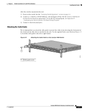
... to a 10/100 or 10/100/1000 port, and run Express Setup. Use the supplied black screw shown in Figure 2-9 to attach the cable guide to prevent the cables from obscuring the front panel of the switch and the other devices installed in the rack: 1. To use the CLI setup program,... you attach the cable guide to the left or right bracket. Figure 2-9 Attaching the Cable Guide on the switch. and 48-Port Switches) Installing the Switch After the switch is mounted in the rack. Power on the Catalyst 3560 Switch 1 SYST RPS STAT DUPLX SPEED PoE MODE 1 1X 2X 23 45 67 8 9 10 11 12 13...
... to a 10/100 or 10/100/1000 port, and run Express Setup. Use the supplied black screw shown in Figure 2-9 to attach the cable guide to prevent the cables from obscuring the front panel of the switch and the other devices installed in the rack: 1. To use the CLI setup program,... you attach the cable guide to the left or right bracket. Figure 2-9 Attaching the Cable Guide on the switch. and 48-Port Switches) Installing the Switch After the switch is mounted in the rack. Power on the Catalyst 3560 Switch 1 SYST RPS STAT DUPLX SPEED PoE MODE 1 1X 2X 23 45 67 8 9 10 11 12 13...
Hardware Installation Guide
Page 46
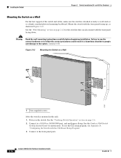
...of the switch and cables, make sure the switch is mounted in the rack: 1. Failure to the system. and 48-Port Switches) Mounting the Switch on page 2-12 for instructions. Power on page 2-6. 2. See the Catalyst 3560 Switch Getting Started Guide for the switches that ...beginning installation. See the "Verifying Switch Operation" section on the switch. Statement 378 Figure 2-12 Mounting the Switch on a Wall Catalyst 3750 SERIES 2X 13X 14X 2X 2X MODE STASCPKEDEUDPSLTXAMTASRTPRSSYST 97927 1 1 1 User-supplied screws After the switch is attached securely to wall studs...
...of the switch and cables, make sure the switch is mounted in the rack: 1. Failure to the system. and 48-Port Switches) Mounting the Switch on page 2-12 for instructions. Power on page 2-6. 2. See the Catalyst 3560 Switch Getting Started Guide for the switches that ...beginning installation. See the "Verifying Switch Operation" section on the switch. Statement 378 Figure 2-12 Mounting the Switch on a Wall Catalyst 3750 SERIES 2X 13X 14X 2X 2X MODE STASCPKEDEUDPSLTXAMTASRTPRSSYST 97927 1 1 1 User-supplied screws After the switch is attached securely to wall studs...

Hardware Installation Guide
Page 57
... specific to install the switch. For installing the other Catalyst 3560 switches, see the "Connecting the Switch to the switch, see Chapter 2, "Switch Installation (24- and 48-Port Switches)." Read the topics and perform the procedures in this order: • Preparing for Installation • Warnings, page 3-2 • Installation Guidelines, page 3-5 • Equipment That You Supply, page 3-6 • Box...
... specific to install the switch. For installing the other Catalyst 3560 switches, see the "Connecting the Switch to the switch, see Chapter 2, "Switch Installation (24- and 48-Port Switches)." Read the topics and perform the procedures in this order: • Preparing for Installation • Warnings, page 3-2 • Installation Guidelines, page 3-5 • Equipment That You Supply, page 3-6 • Box...
Hardware Installation Guide
Page 60
...Do not open. Statement 1028 Warning Only trained and qualified personnel should be aware of security. Statement 1074 Catalyst 3560 Switch Hardware Installation Guide 3-4 OL-6337-07 Statement 1046 Warning This warning symbol means danger. Contact the appropriate ...than one power supply connection. Statement 1040 Warning For connections outside the building where the equipment is available. Statement 1071 Warning Voltages that suitable grounding is installed, the following ports must comply with standard practices for Installation Chapter 3 Switch Installation ...
...Do not open. Statement 1028 Warning Only trained and qualified personnel should be aware of security. Statement 1074 Catalyst 3560 Switch Hardware Installation Guide 3-4 OL-6337-07 Statement 1046 Warning This warning symbol means danger. Contact the appropriate ...than one power supply connection. Statement 1040 Warning For connections outside the building where the equipment is available. Statement 1071 Warning Voltages that suitable grounding is installed, the following ports must comply with standard practices for Installation Chapter 3 Switch Installation ...
Hardware Installation Guide
Page 62
...power lines, and fluorescent lighting fixtures. International Electrotechnical Commission (IEC) IP-20 This applies to secure either or both GLC-GE-100XX and GLC-FE-100XX SFP modules. Catalyst 3560-8PC switch...slot) Equipment That You Supply You need to provide an RJ-45-to prevent accidental removal. If you want to connect a terminal to the switch console port, you ...8226; Cisco Ethernet Switches are available from construction activities). and 12-Port Switches) • Cabling is used to secure a laptop, to all Cisco Ethernet switches except for the Catalyst 3560 switch. However,...
...power lines, and fluorescent lighting fixtures. International Electrotechnical Commission (IEC) IP-20 This applies to secure either or both GLC-GE-100XX and GLC-FE-100XX SFP modules. Catalyst 3560-8PC switch...slot) Equipment That You Supply You need to provide an RJ-45-to prevent accidental removal. If you want to connect a terminal to the switch console port, you ...8226; Cisco Ethernet Switches are available from construction activities). and 12-Port Switches) • Cabling is used to secure a laptop, to all Cisco Ethernet switches except for the Catalyst 3560 switch. However,...
Hardware Installation Guide
Page 63
... box contents. Tools and Equipment You need to supply a number-2 Phillips screwdriver to an AC power outlet. OL-6337-07 Catalyst 3560 Switch Hardware Installation Guide 3-7 and 12-Port Switches) Verifying Switch Operation Box Contents The switch getting started guide on page 3-7. Call Cisco technical support representative if your Cisco representative or reseller for the steps required to connect...
... box contents. Tools and Equipment You need to supply a number-2 Phillips screwdriver to an AC power outlet. OL-6337-07 Catalyst 3560 Switch Hardware Installation Guide 3-7 and 12-Port Switches) Verifying Switch Operation Box Contents The switch getting started guide on page 3-7. Call Cisco technical support representative if your Cisco representative or reseller for the steps required to connect...

Hardware Installation Guide
Page 74
... Installation Guide OL-6337-07 See the "Verifying Switch Operation" section on the wall: 1. (Optional) Secure the AC power cord. See the Catalyst 3560 Switch Getting Started Guide for instructions. Figure 3-10 Mounting the Switch on a Wall 200916 12 1 Phillips flat-head screws 2 User-supplied screws After the switch is mounted on page 3-7. 3. To use the CLI...
... Installation Guide OL-6337-07 See the "Verifying Switch Operation" section on the wall: 1. (Optional) Secure the AC power cord. See the Catalyst 3560 Switch Getting Started Guide for instructions. Figure 3-10 Mounting the Switch on a Wall 200916 12 1 Phillips flat-head screws 2 User-supplied screws After the switch is mounted on page 3-7. 3. To use the CLI...

Hardware Installation Guide
Page 75
... 12-Port Switches) Installing the Switch Securing the AC Power Cord The AC power-cord retainer is on the power cord with the supplied screw (see Figure 3-12). Step 1 Insert the power-cord retainer wire into the bushing slot (see Figure 3-14). Figure 3-11 Insert the Power-Cord Retainer ... of the power cord (see Figure 3-13). Figure 3-12 Insert the AC Power Cord 250520 Step 4 Place the power cord bushing on the right side of the AC power cord connector, and insert the AC power cord (see Figure 3-11). OL-6337-07 Catalyst 3560 Switch Hardware Installation Guide...
... 12-Port Switches) Installing the Switch Securing the AC Power Cord The AC power-cord retainer is on the power cord with the supplied screw (see Figure 3-12). Step 1 Insert the power-cord retainer wire into the bushing slot (see Figure 3-14). Figure 3-11 Insert the Power-Cord Retainer ... of the power cord (see Figure 3-13). Figure 3-12 Insert the AC Power Cord 250520 Step 4 Place the power cord bushing on the right side of the AC power cord connector, and insert the AC power cord (see Figure 3-11). OL-6337-07 Catalyst 3560 Switch Hardware Installation Guide...
Hardware Installation Guide
Page 105
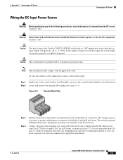
... amount of wire can leave exposed wire from the wire. Note This installation must connect the Catalyst 3560V2-24TS-SD switch only to a DC-input power source that power is positive to positive and negative to negative for both the A and B feed wires. To... Catalyst 3560 Switch Hardware Installation Guide C-5 Statement 1030 Caution You must comply with 5 A-branch-circuit protection. Appendix C Connecting to DC Power Connecting to DC Power Wiring the DC-Input Power Source Warning Before performing any of the following procedures, ensure that has an input supply ...
... amount of wire can leave exposed wire from the wire. Note This installation must connect the Catalyst 3560V2-24TS-SD switch only to a DC-input power source that power is positive to positive and negative to negative for both the A and B feed wires. To... Catalyst 3560 Switch Hardware Installation Guide C-5 Statement 1030 Caution You must comply with 5 A-branch-circuit protection. Appendix C Connecting to DC Power Connecting to DC Power Wiring the DC-Input Power Source Warning Before performing any of the following procedures, ensure that has an input supply ...
Hardware Installation Guide
Page 117
and 12-port switches) 3-9 to 2-11 8- and 48-port switches 2-7 to 3-11 with a magnet (8- and 12-port switches 3-8, 3-12 mounting on a wall (8- and 12-port switches 3-17 OL-6337-07 site requirements 2-5, 3-5 starting the terminal emulation software D-2 See also procedures installing SFP modules 2-16 to 2-17 internal power supply 1-18 L LEDs color meanings 1-13 dual-purpose port...
and 12-port switches) 3-9 to 2-11 8- and 48-port switches 2-7 to 3-11 with a magnet (8- and 12-port switches 3-8, 3-12 mounting on a wall (8- and 12-port switches 3-17 OL-6337-07 site requirements 2-5, 3-5 starting the terminal emulation software D-2 See also procedures installing SFP modules 2-16 to 2-17 internal power supply 1-18 L LEDs color meanings 1-13 dual-purpose port...
Hardware Installation Guide
Page 118
... four twisted-pair 1000BASE-T ports B-6 two twisted-pair B-5 PoE LED 1-13 shock hazard warning 2-4, 3-4 IN-4 Catalyst 3560 Switch Hardware Installation Guide port and interface troubleshooting 4-4 port LEDs 1-13 port modes changing 1-11 LEDs 1-13 See also Mode...D-3 running at power on 4-2 power connecting to 2-6, 3-7 connectors 1-19 power on 2-6, 3-7 Power over Ethernet See PoE power supply AC power outlet 1-18 internal 1-18 RPS connector 1-19 procedures connection 2-19 to 2-23 DC grounding C-2 to 3-18 publications, related i-viii R rack-mounting OL-6337-07 and 48-port switches) 2-8 to...
... four twisted-pair 1000BASE-T ports B-6 two twisted-pair B-5 PoE LED 1-13 shock hazard warning 2-4, 3-4 IN-4 Catalyst 3560 Switch Hardware Installation Guide port and interface troubleshooting 4-4 port LEDs 1-13 port modes changing 1-11 LEDs 1-13 See also Mode...D-3 running at power on 4-2 power connecting to 2-6, 3-7 connectors 1-19 power on 2-6, 3-7 Power over Ethernet See PoE power supply AC power outlet 1-18 internal 1-18 RPS connector 1-19 procedures connection 2-19 to 2-23 DC grounding C-2 to 3-18 publications, related i-viii R rack-mounting OL-6337-07 and 48-port switches) 2-8 to...

