
Installation Guide
Page 6
... A P T E R LEDs 1-11 System LED 1-14 RPS LED 1-15 Port LEDs and Modes 1-16 Rear-Panel Description 1-21 Power Connectors 1-22 Internal Power Supply Connector 1-23 Cisco RPS Connector 1-23 Console Port 1-24 Management Options 1-24 Network Configuration Examples 1-25 Design Concepts for Installation 2-2 Warnings 2-2 EMC Regulatory Statements 2-5 U.S.A. 2-5 Taiwan 2-5 Japan 2-6 Korea 2-6 Hungary 2-7 Installation Guidelines 2-7 Verifying Package Contents 2-8 Catalyst 3500 Series XL Hardware Installation Guide vi 78-6456-03 to Medium-Sized Network Configuration 1-29 Collapsed Backbone and Switch...
... A P T E R LEDs 1-11 System LED 1-14 RPS LED 1-15 Port LEDs and Modes 1-16 Rear-Panel Description 1-21 Power Connectors 1-22 Internal Power Supply Connector 1-23 Cisco RPS Connector 1-23 Console Port 1-24 Management Options 1-24 Network Configuration Examples 1-25 Design Concepts for Installation 2-2 Warnings 2-2 EMC Regulatory Statements 2-5 U.S.A. 2-5 Taiwan 2-5 Japan 2-6 Korea 2-6 Hungary 2-7 Installation Guidelines 2-7 Verifying Package Contents 2-8 Catalyst 3500 Series XL Hardware Installation Guide vi 78-6456-03 to Medium-Sized Network Configuration 1-29 Collapsed Backbone and Switch...

Installation Guide
Page 12
... angle brackets (< >). Catalyst 3500 Series XL Hardware Installation Guide xii 78-6456-04 Chapter 2, "Installing and Starting Up the Switch," contains the procedures for the switches and the regulatory agency approvals. Appendix B, "Connector and Cable Specifications," describes the connectors, cables, and adapters that might arise when you are installing the switch. Chapter 3, "Troubleshooting," describes how to the switch. Examples of how the switch could be used to connect to identify...
... angle brackets (< >). Catalyst 3500 Series XL Hardware Installation Guide xii 78-6456-04 Chapter 2, "Installing and Starting Up the Switch," contains the procedures for the switches and the regulatory agency approvals. Appendix B, "Connector and Cable Specifications," describes the connectors, cables, and adapters that might arise when you are installing the switch. Chapter 3, "Troubleshooting," describes how to the switch. Examples of how the switch could be used to connect to identify...

Installation Guide
Page 25
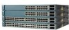
... network devices such as backbone switches, aggregating 10/100 and Gigabit Ethernet traffic from other switches. A feature specific to the Catalyst 3524-PWR XL switch is its ability to provide inline power to Cisco IP Phones. (Phone adapters are stackable 10/100 Ethernet switches to the Catalyst 3524-PWR XL 10/100 switch ports.) Figure 1-1 shows the switch models in the series, and Table 1-1 and Table 1-2 list their features. 78-6456-04 Catalyst 3500 Series XL Hardware Installation Guide...
... network devices such as backbone switches, aggregating 10/100 and Gigabit Ethernet traffic from other switches. A feature specific to the Catalyst 3524-PWR XL switch is its ability to provide inline power to Cisco IP Phones. (Phone adapters are stackable 10/100 Ethernet switches to the Catalyst 3524-PWR XL 10/100 switch ports.) Figure 1-1 shows the switch models in the series, and Table 1-1 and Table 1-2 list their features. 78-6456-04 Catalyst 3500 Series XL Hardware Installation Guide...

Installation Guide
Page 27
... Cisco 600W Redundant Power System (RPS) that operates on AC input and supplies DC output to four 1000BaseZX GBICs with the Catalyst 3508G XL switch) Management • Cisco IOS command-line interface (CLI) through the console port or Telnet • CiscoView device-management application • Cluster Management Suite, a web-based tool for managing switch clusters or an individual switch through a single IP address • Simple Network Management Protocol (SNMP) Power Redundancy • Connection for Cisco Gigabit Interface Converter (GBIC) modules...
... Cisco 600W Redundant Power System (RPS) that operates on AC input and supplies DC output to four 1000BaseZX GBICs with the Catalyst 3508G XL switch) Management • Cisco IOS command-line interface (CLI) through the console port or Telnet • CiscoView device-management application • Cluster Management Suite, a web-based tool for managing switch clusters or an individual switch through a single IP address • Simple Network Management Protocol (SNMP) Power Redundancy • Connection for Cisco Gigabit Interface Converter (GBIC) modules...

Installation Guide
Page 29
...-Panel Description Table 1-2 Catalyst 3512, 3524, 3524-PWR, and 3548 XL Features (continued) Feature Description (continued) Management • Cisco IOS CLI through the console port or Telnet • CiscoView device-management application • Cluster Management Suite, a web-based tool for managing switch clusters or an individual switch through a single IP address • SNMP Power Redundancy • Connection for optional Cisco RPS 600 that operates on AC input and supplies DC...
...-Panel Description Table 1-2 Catalyst 3512, 3524, 3524-PWR, and 3548 XL Features (continued) Feature Description (continued) Management • Cisco IOS CLI through the console port or Telnet • CiscoView device-management application • Cluster Management Suite, a web-based tool for managing switch clusters or an individual switch through a single IP address • SNMP Power Redundancy • Connection for optional Cisco RPS 600 that operates on AC input and supplies DC...

Installation Guide
Page 32
... full-duplex transmission, if the attached device supports it) and configures itself accordingly. These ports also can control whether or not a Catalyst 3524-PWR XL 10/100 port automatically provides power when a Cisco IP Phone is required for each 10/100 port: Auto and Never. CMS and the CLI provide two inline power settings for 100BaseTX traffic. When connecting the switch to operate in Appendix B, "Connector and Cable Specifications." Refer...
... full-duplex transmission, if the attached device supports it) and configures itself accordingly. These ports also can control whether or not a Catalyst 3524-PWR XL 10/100 port automatically provides power when a Cisco IP Phone is required for each 10/100 port: Auto and Never. CMS and the CLI provide two inline power settings for 100BaseTX traffic. When connecting the switch to operate in Appendix B, "Connector and Cable Specifications." Refer...

Installation Guide
Page 33
... configuration) or up to nine half-duplex links (in the Catalyst 3508G XL switch. Using the required Cisco proprietary signaling and cabling, the maximum distance for a GigaStack GBIC-to which the Cisco IP Phone is first connected becomes its primary power source, and the second power source is its backup. Note GBIC modules are not factory-installed on these switches, but you select the Never setting for redundant power. Refer...
... configuration) or up to nine half-duplex links (in the Catalyst 3508G XL switch. Using the required Cisco proprietary signaling and cabling, the maximum distance for a GigaStack GBIC-to which the Cisco IP Phone is first connected becomes its primary power source, and the second power source is its backup. Note GBIC modules are not factory-installed on these switches, but you select the Never setting for redundant power. Refer...

Installation Guide
Page 39
... Cisco RPS 300 (model PWR300-AC-RPS) supports the Catalyst 3524-PWR XL switch. 78-6456-04 Catalyst 3500 Series XL Hardware Installation Guide 1-15 RPS and the switch AC power supply are using power from the RPS. The switch goes through its normal boot sequence when it restarts. Note This is not a recommended configuration. Table 1-4 and Table 1-5 list the LED colors and their meanings. Note The Cisco RPS 600 (model PWR600-AC-RPS) supports...
... Cisco RPS 300 (model PWR300-AC-RPS) supports the Catalyst 3524-PWR XL switch. 78-6456-04 Catalyst 3500 Series XL Hardware Installation Guide 1-15 RPS and the switch AC power supply are using power from the RPS. The switch goes through its normal boot sequence when it restarts. Note This is not a recommended configuration. Table 1-4 and Table 1-5 list the LED colors and their meanings. Note The Cisco RPS 600 (model PWR600-AC-RPS) supports...

Installation Guide
Page 40
... the individual ports. When you change a mode, press the Mode button until the desired mode is backing up another switch in the Catalyst 3548 XL switch, press the Mode label. RPS is highlighted. Internal power supply of the power supplies in use by the switch. 1-16 Catalyst 3500 Series XL Hardware Installation Guide 78-6456-04 The port modes (Table 1-6) determine the type of the port LED colors also changes. One of the switch is down , or a fan on the...
... the individual ports. When you change a mode, press the Mode button until the desired mode is backing up another switch in the Catalyst 3548 XL switch, press the Mode label. RPS is highlighted. Internal power supply of the power supplies in use by the switch. 1-16 Catalyst 3500 Series XL Hardware Installation Guide 78-6456-04 The port modes (Table 1-6) determine the type of the port LED colors also changes. One of the switch is down , or a fan on the...

Installation Guide
Page 41
... Table 1-6 Port Mode LEDs (continued) Mode LED DUPLX SPEED LINE PWR Port Mode Port duplex mode Port speed Port inline power Description The port duplex mode: full duplex or half duplex. If all port LEDs are monitored for a link-fault indication. Port is not forwarding. The port operating speed: 10, 100, or 1000 Mbps. Activity. Link fault. Port is operating in full duplex. 78-6456-04 Catalyst 3500 Series XL Hardware Installation Guide 1-17 If the LED to 30 seconds as excessive collisions, CRC errors, and alignment and jabber errors are green...
... Table 1-6 Port Mode LEDs (continued) Mode LED DUPLX SPEED LINE PWR Port Mode Port duplex mode Port speed Port inline power Description The port duplex mode: full duplex or half duplex. If all port LEDs are monitored for a link-fault indication. Port is not forwarding. The port operating speed: 10, 100, or 1000 Mbps. Activity. Link fault. Port is operating in full duplex. 78-6456-04 Catalyst 3500 Series XL Hardware Installation Guide 1-17 If the LED to 30 seconds as excessive collisions, CRC errors, and alignment and jabber errors are green...

Installation Guide
Page 48
... Catalyst 3500 Series XL Hardware Installation Guide 78-6456-04 For console port and adapter pinout information, see the "Cable and Adapter Specifications" section on the Catalyst 3524-PWR XL Switch The Cisco RPS 300 (model PWR300-AC-RPS) has two output levels: -48V and 12V with a total output power of four web-based applications that adapter from Cisco. You use the Visual Switch Manager (VSM) application to the Cisco IOS Desktop Switching Software Configuration Guide and...
... Catalyst 3500 Series XL Hardware Installation Guide 78-6456-04 For console port and adapter pinout information, see the "Cable and Adapter Specifications" section on the Catalyst 3524-PWR XL Switch The Cisco RPS 300 (model PWR300-AC-RPS) has two output levels: -48V and 12V with a total output power of four web-based applications that adapter from Cisco. You use the Visual Switch Manager (VSM) application to the Cisco IOS Desktop Switching Software Configuration Guide and...
Installation Guide
Page 49
... CiscoView device-management application displays the switch image that you purchase separately, can use to set of the network applications they use a Telnet connection to manage the switch from a remote location. Chapter 1 Product Overview Network Configuration Examples • Cisco IOS command-line interface (CLI) Connect a PC or terminal directly to the console port, located on the rear panel of using the switch to create dedicated network segments and interconnecting the segments through Fast Ethernet and Gigabit Ethernet connections. See the documentation that is...
... CiscoView device-management application displays the switch image that you purchase separately, can use to set of the network applications they use a Telnet connection to manage the switch from a remote location. Chapter 1 Product Overview Network Configuration Examples • Cisco IOS command-line interface (CLI) Connect a PC or terminal directly to the console port, located on the rear panel of using the switch to create dedicated network segments and interconnecting the segments through Fast Ethernet and Gigabit Ethernet connections. See the documentation that is...

Installation Guide
Page 50
... between the switch and its connected servers and routers. • An evolving demand for using Fast Ethernet or gigabit links or Fast EtherChannel or Gigabit EtherChannel links. To preserve connectivity between Catalyst 4908G-L3 switches. You can create backup paths between the switches in case one switch in the same logical network as the users who access those resources most. • Use full-duplex operation between the switch and its connected workstations. • The increased power of...
... between the switch and its connected servers and routers. • An evolving demand for using Fast Ethernet or gigabit links or Fast EtherChannel or Gigabit EtherChannel links. To preserve connectivity between Catalyst 4908G-L3 switches. You can create backup paths between the switches in case one switch in the same logical network as the users who access those resources most. • Use full-duplex operation between the switch and its connected workstations. • The increased power of...

Installation Guide
Page 55
... Series XL Hardware Installation Guide 1-31 You also configure each port for monitoring and controlling the network. Each 10/100 inline-power port on WAN access. Grouping servers in a centralized location provides benefits such as illustrated, or into a single cluster. Using Cisco IP Phones, Cisco CallManager software, and Cisco SoftPhone software integrates telephony and IP networks, where the IP network supports both voice and data. A Catalyst 4908G-L3 backbone switch provides the benefits of inter-VLAN routing...
... Series XL Hardware Installation Guide 1-31 You also configure each port for monitoring and controlling the network. Each 10/100 inline-power port on WAN access. Grouping servers in a centralized location provides benefits such as illustrated, or into a single cluster. Using Cisco IP Phones, Cisco CallManager software, and Cisco SoftPhone software integrates telephony and IP networks, where the IP network supports both voice and data. A Catalyst 4908G-L3 backbone switch provides the benefits of inter-VLAN routing...
Installation Guide
Page 59
... are presented: • Pre-installation information and guidelines • Installation procedures • Power-on procedures • Connection procedures • Set up your Catalyst 3500 XL switches and to go next 78-6456-04 Catalyst 3500 Series XL Hardware Installation Guide 2-1 CH A P T E R 2 Installing and Starting Up the Switch This chapter describes how to install and start up procedures for initial configuration • Default configuration settings • Where to interpret the...
... are presented: • Pre-installation information and guidelines • Installation procedures • Power-on procedures • Connection procedures • Set up your Catalyst 3500 XL switches and to go next 78-6456-04 Catalyst 3500 Series XL Hardware Installation Guide 2-1 CH A P T E R 2 Installing and Starting Up the Switch This chapter describes how to install and start up procedures for initial configuration • Default configuration settings • Where to interpret the...
Installation Guide
Page 83
... Up the Switch Assigning Switch Information Using the Setup Program You can use the Cluster Management Suite or the command-line interface (CLI) to customize your system administrator: Switch IP address Subnet mask (netmask 78-6456-04 Catalyst 3500 Series XL Hardware Installation Guide 2-25 If you are configuring a command switch or standalone switch, you need the following information from the PC terminal that prompts you plan to use an automatic setup program to...
... Up the Switch Assigning Switch Information Using the Setup Program You can use the Cluster Management Suite or the command-line interface (CLI) to customize your system administrator: Switch IP address Subnet mask (netmask 78-6456-04 Catalyst 3500 Series XL Hardware Installation Guide 2-25 If you are configuring a command switch or standalone switch, you need the following information from the PC terminal that prompts you plan to use an automatic setup program to...
Installation Guide
Page 87
... time it transmits a BOOTP broadcast request to a Catalyst 3500 XL switch. If the switch starts and no IP address has been assigned, it resets. The switch must be stored in Table 2-1. 78-6456-04 Catalyst 3500 Series XL Hardware Installation Guide 2-29 The reception of a valid BOOTP response immediately activates the rest of its connected ports, requesting a mapping for its ports. Chapter 2 Installing and Starting Up the Switch Default Configuration Settings Using...
... time it transmits a BOOTP broadcast request to a Catalyst 3500 XL switch. If the switch starts and no IP address has been assigned, it resets. The switch must be stored in Table 2-1. 78-6456-04 Catalyst 3500 Series XL Hardware Installation Guide 2-29 The reception of a valid BOOTP response immediately activates the rest of its connected ports, requesting a mapping for its ports. Chapter 2 Installing and Starting Up the Switch Default Configuration Settings Using...
Installation Guide
Page 89
...04 Catalyst 3500 Series XL Hardware Installation Guide 2-31 ARP = Address Resolution Protocol 3. Chapter 2 Installing and Starting Up the Switch Where to change the default configuration: • Start the Cluster Management Suite, as described in Table 2-1 is satisfactory, the switch does not need further configuration. SPAN = Switched Port Analyzer Default Setting Disabled. None. Refer to configure the switch from the console. Disabled. VLAN = Virtual Local Area Network 4. Where to Go Next If the default configuration shown in the Cisco IOS Desktop Switching Software...
...04 Catalyst 3500 Series XL Hardware Installation Guide 2-31 ARP = Address Resolution Protocol 3. Chapter 2 Installing and Starting Up the Switch Where to change the default configuration: • Start the Cluster Management Suite, as described in Table 2-1 is satisfactory, the switch does not need further configuration. SPAN = Switched Port Analyzer Default Setting Disabled. None. Refer to configure the switch from the console. Disabled. VLAN = Virtual Local Area Network 4. Where to Go Next If the default configuration shown in the Cisco IOS Desktop Switching Software...

Installation Guide
Page 91
... get statistics from the browser interface, from the command-line interface (CLI), or from an Simple Network Management Protocol (SNMP) workstation. See the Cisco IOS Desktop Switching Software Configuration Guide, the Cisco IOS Desktop Switching Command Reference (online only), or the documentation that came with your SNMP application for troubleshooting problems: • Understanding POST results • Diagnosing problems 78-6456-04 Catalyst 3500 Series XL Hardware Installation Guide 3-1 They show failures in the power-on page 1-11. This...
... get statistics from the browser interface, from the command-line interface (CLI), or from an Simple Network Management Protocol (SNMP) workstation. See the Cisco IOS Desktop Switching Software Configuration Guide, the Cisco IOS Desktop Switching Command Reference (online only), or the documentation that came with your SNMP application for troubleshooting problems: • Understanding POST results • Diagnosing problems 78-6456-04 Catalyst 3500 Series XL Hardware Installation Guide 3-1 They show failures in the power-on page 1-11. This...

Installation Guide
Page 96
... switch to overheat, replace the switch. • Use the show env command to see which POST test failed. Catalyst 3500 Series XL Hardware Installation Guide 3-6 78-6456-04 Resolution • Either check the switch itself or use the show POST command to check if a fan on the Catalyst 3524-PWR XL. Make sure fan intake and exhaust areas are clear. Diagnosing Problems Chapter 3 Troubleshooting Table 3-2 Common Problems and Their Solutions (continued) Symptom System LED is amber...
... switch to overheat, replace the switch. • Use the show env command to see which POST test failed. Catalyst 3500 Series XL Hardware Installation Guide 3-6 78-6456-04 Resolution • Either check the switch itself or use the show POST command to check if a fan on the Catalyst 3524-PWR XL. Make sure fan intake and exhaust areas are clear. Diagnosing Problems Chapter 3 Troubleshooting Table 3-2 Common Problems and Their Solutions (continued) Symptom System LED is amber...


