
Installation Guide
Page 6
... Configuration 1-31 Large Campus Configuration 1-33 Installing and Starting Up the Switch 2-1 Preparing for Using the Switch 1-25 Small- Contents 2 C H A P T E R LEDs 1-11 System LED 1-14 RPS LED 1-15 Port LEDs and Modes 1-16 Rear-Panel Description 1-21 Power Connectors 1-22 Internal Power Supply Connector 1-23 Cisco RPS Connector 1-23 Console Port 1-24 Management Options 1-24 Network...
... Configuration 1-31 Large Campus Configuration 1-33 Installing and Starting Up the Switch 2-1 Preparing for Using the Switch 1-25 Small- Contents 2 C H A P T E R LEDs 1-11 System LED 1-14 RPS LED 1-15 Port LEDs and Modes 1-16 Rear-Panel Description 1-21 Power Connectors 1-22 Internal Power Supply Connector 1-23 Cisco RPS Connector 1-23 Console Port 1-24 Management Options 1-24 Network...

Installation Guide
Page 9
INDEX Grounded Equipment Warning C-23 Supply Circuit Warning C-24 No On/Off Switch Warning C-25 Power Supply Warning C-27 Work During Lightning Activity Warning C-30 Product Disposal Warning C-31 Chassis Warning-Rack-Mounting and Servicing C-33 Chassis Power Connection Warning C-38 Shock Hazard from Interconnections Warning C-41 Contents 78-6456-03 Catalyst 3500 Series XL Hardware Installation Guide ix
INDEX Grounded Equipment Warning C-23 Supply Circuit Warning C-24 No On/Off Switch Warning C-25 Power Supply Warning C-27 Work During Lightning Activity Warning C-30 Product Disposal Warning C-31 Chassis Warning-Rack-Mounting and Servicing C-33 Chassis Power Connection Warning C-38 Shock Hazard from Interconnections Warning C-41 Contents 78-6456-03 Catalyst 3500 Series XL Hardware Installation Guide ix

Installation Guide
Page 39
... but not functioning properly. Note The Cisco RPS 300 (model PWR300-AC-RPS) supports the Catalyst 3524-PWR XL switch. 78-6456-04 Catalyst 3500 Series XL Hardware Installation Guide 1-15 If the switch power supply fails, the switch powers down , or a fan on the bottom of the power supplies in the RPS could be powered down and restarts after 15 seconds...
... but not functioning properly. Note The Cisco RPS 300 (model PWR300-AC-RPS) supports the Catalyst 3524-PWR XL switch. 78-6456-04 Catalyst 3500 Series XL Hardware Installation Guide 1-15 If the switch power supply fails, the switch powers down , or a fan on the bottom of the power supplies in the RPS could be powered down and restarts after 15 seconds...

Installation Guide
Page 40
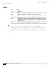
... label. RPS is highlighted. One of the switch is down , or a fan on the Cisco RPS 300, refer to interpret the port LED colors after you change the port mode in the stack. RPS is lost. Internal power supply of the power supplies in use by the switch. 1-16 Catalyst 3500 Series XL Hardware Installation Guide 78-6456...
... label. RPS is highlighted. One of the switch is down , or a fan on the Cisco RPS 300, refer to interpret the port LED colors after you change the port mode in the stack. RPS is lost. Internal power supply of the power supplies in use by the switch. 1-16 Catalyst 3500 Series XL Hardware Installation Guide 78-6456...

Installation Guide
Page 45
...-6456-04 CONSOLE DC INPUTS FOR REMOTE POWER SUPPLY SPECIFIED IN MANUAL. +5V @24A, +12V @.5A RJ-45 console port Redundant power system connector Fans Catalyst 3500 Series XL Hardware Installation Guide 1-21 Chapter 1 Product Overview Rear-Panel Description Rear-Panel Description Switch rear panels have an AC power connector, an RPS connector, and an RJ...
...-6456-04 CONSOLE DC INPUTS FOR REMOTE POWER SUPPLY SPECIFIED IN MANUAL. +5V @24A, +12V @.5A RJ-45 console port Redundant power system connector Fans Catalyst 3500 Series XL Hardware Installation Guide 1-21 Chapter 1 Product Overview Rear-Panel Description Rear-Panel Description Switch rear panels have an AC power connector, an RPS connector, and an RJ...

Installation Guide
Page 46
...~ 1.6A/0.9A 50-60HZ DC INPUTS FOR REMOTE POWER SUPPLY SPECIFIED IN MANUAL +3.3V @17A, +12 @1.1A CONSOLE AC power connector Fan exhaust RJ-45 console port Redundant power system connector Power Connectors You can provide power to the switch either through the internal power supply or through the Cisco RPS. 1-22 Catalyst 3500 Series XL Hardware Installation Guide 78-6456...
...~ 1.6A/0.9A 50-60HZ DC INPUTS FOR REMOTE POWER SUPPLY SPECIFIED IN MANUAL +3.3V @17A, +12 @1.1A CONSOLE AC power connector Fan exhaust RJ-45 console port Redundant power system connector Power Connectors You can provide power to the switch either through the internal power supply or through the Cisco RPS. 1-22 Catalyst 3500 Series XL Hardware Installation Guide 78-6456...

Installation Guide
Page 47
... Internal Power Supply Connector The internal power supply is an autoranging unit that use the supplied AC power cord to connect the AC power connector to 150W DC each. The power source is not recommended. If you plan to use the internal power supply, use up to an AC power outlet. Cisco RPS Connector Specific Cisco RPS models support specific Catalyst 3500 XL switches: • Cisco...
... Internal Power Supply Connector The internal power supply is an autoranging unit that use the supplied AC power cord to connect the AC power connector to 150W DC each. The power source is not recommended. If you plan to use the internal power supply, use up to an AC power outlet. Cisco RPS Connector Specific Cisco RPS models support specific Catalyst 3500 XL switches: • Cisco...
Installation Guide
Page 62
... are authorized to access the location are present within the power supply when the power cord is connected. Statement 1072 The following warning applies to the Catalyst 3508, 3512, 3524, and 3548 XL switches: Warning Attach only the Cisco RPS (model PWR600-AC-RPS) to all power is OFF, locate the circuit breaker on the panel board...
... are authorized to access the location are present within the power supply when the power cord is connected. Statement 1072 The following warning applies to the Catalyst 3508, 3512, 3524, and 3548 XL switches: Warning Attach only the Cisco RPS (model PWR600-AC-RPS) to all power is OFF, locate the circuit breaker on the panel board...
Installation Guide
Page 82
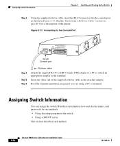
...Figure 2-13 Connecting to the Console Port 32709 CONSOLE DC INPUTS FOR REMOTE POWER SUPPLY SPECIFIED IN MANUAL. +5V @24A, +12V @1.0A RJ-45 Console port Step 4 Step 5 Step 6 Rollover cable Attach the supplied RJ-45-to-DB-9 female DTE adapter to a PC or attach an ... section on page B-5 for a description of the supplied rollover cable in the switch • Using a BOOTP server This section describes each method. 2-24 Catalyst 3500 Series XL Hardware Installation Guide 78-6456-04 Assigning Switch Information You can assign the switch IP address information, host and cluster names, and...
...Figure 2-13 Connecting to the Console Port 32709 CONSOLE DC INPUTS FOR REMOTE POWER SUPPLY SPECIFIED IN MANUAL. +5V @24A, +12V @1.0A RJ-45 Console port Step 4 Step 5 Step 6 Rollover cable Attach the supplied RJ-45-to-DB-9 female DTE adapter to a PC or attach an ... section on page B-5 for a description of the supplied rollover cable in the switch • Using a BOOTP server This section describes each method. 2-24 Catalyst 3500 Series XL Hardware Installation Guide 78-6456-04 Assigning Switch Information You can assign the switch IP address information, host and cluster names, and...
Installation Guide
Page 137
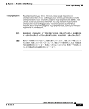
Appendix C Translated Safety Warnings Power Supply Warning 78-6456-04 Catalyst 3500 Series XL Hardware Installation Guide C-29
Appendix C Translated Safety Warnings Power Supply Warning 78-6456-04 Catalyst 3500 Series XL Hardware Installation Guide C-29
Installation Guide
Page 157
... 2-24 installation 2-7 to 2-17 IP address 2-24 product disposal warning C-31 PSTN 1-33 publications, related xviii Public Switched Telephone Network See PSTN Q qualified personnel warning C-7 R rack installation 2-9 bracket mounting points 2-10 rack-mounting 2-13 rear panel 1-21 to 1-22 clearance 2-8 Redundant Power Supply 78-6456-04 Catalyst 3500 Series XL Hardware Installation Guide IN-5
... 2-24 installation 2-7 to 2-17 IP address 2-24 product disposal warning C-31 PSTN 1-33 publications, related xviii Public Switched Telephone Network See PSTN Q qualified personnel warning C-7 R rack installation 2-9 bracket mounting points 2-10 rack-mounting 2-13 rear panel 1-21 to 1-22 clearance 2-8 Redundant Power Supply 78-6456-04 Catalyst 3500 Series XL Hardware Installation Guide IN-5

Hardware Installation Guide
Page 3
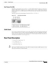
... i-viii Obtaining Documentation and Submitting a Service Request i-ix Product Overview 1-1 Setting Up the Switch 1-1 Features 1-1 Front Panel Description 1-3 Fast Ethernet Switch Front Panel Descriptions 1-3 Gigabit Ethernet Switch Front Panel Descriptions 1-6 10/100 and 10/100/1000 Ports 1-8 PoE Ports 1-9 SFP ...Purpose Port LEDs 1-15 Cable Guard 1-15 Rear Panel Description 1-15 Internal Power Supply 1-18 DC Power Connector 1-18 Cisco RPS 1-19 Cisco RPS 2300 1-19 Cisco RPS 675 1-19 Console Port 1-19 Security Slots 1-20 Management Options 1-20 Catalyst 3560 Switch Hardware Installation Guide iii
... i-viii Obtaining Documentation and Submitting a Service Request i-ix Product Overview 1-1 Setting Up the Switch 1-1 Features 1-1 Front Panel Description 1-3 Fast Ethernet Switch Front Panel Descriptions 1-3 Gigabit Ethernet Switch Front Panel Descriptions 1-6 10/100 and 10/100/1000 Ports 1-8 PoE Ports 1-9 SFP ...Purpose Port LEDs 1-15 Cable Guard 1-15 Rear Panel Description 1-15 Internal Power Supply 1-18 DC Power Connector 1-18 Cisco RPS 1-19 Cisco RPS 2300 1-19 Cisco RPS 675 1-19 Console Port 1-19 Security Slots 1-20 Management Options 1-20 Catalyst 3560 Switch Hardware Installation Guide iii
Hardware Installation Guide
Page 22
... another device (redundancy has been allocated to this device). Contact Cisco. Note The Catalyst 3560-8PC and Catalyst 3560-12PC-S switches do not have failed. The RPS is off or not properly connected. The internal power supply in a fault condition. RPS is providing power to the switch (redundancy has been allocated to a neighboring device). If it is unavailable...
... another device (redundancy has been allocated to this device). Contact Cisco. Note The Catalyst 3560-8PC and Catalyst 3560-12PC-S switches do not have failed. The RPS is off or not properly connected. The internal power supply in a fault condition. RPS is providing power to the switch (redundancy has been allocated to a neighboring device). If it is unavailable...
Hardware Installation Guide
Page 25
...) show how the port is on page 2-11). Rear Panel Description • Internal Power Supply, page 1-18 • Cisco RPS, page 1-19 • Console Port, page 1-19 • Security Slots, page 1-20 Note The Catalyst 3560-8PC and the Catalyst 3560-12PC-S switches do not have the same meaning as an SFP module, but not both...
...) show how the port is on page 2-11). Rear Panel Description • Internal Power Supply, page 1-18 • Cisco RPS, page 1-19 • Console Port, page 1-19 • Security Slots, page 1-20 Note The Catalyst 3560-8PC and the Catalyst 3560-12PC-S switches do not have the same meaning as an SFP module, but not both...
Hardware Installation Guide
Page 28
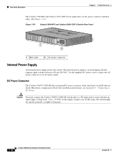
...-power converter. For installation instructions, see Appendix C, "Connecting to DC Power." Rear Panel Description Chapter 1 Product Overview The Catalyst 3560-8PC and Catalyst 3560-12PC-S rear panels have an AC power connector and heat sinks. (See Figure 1-18.) Figure 1-18 Catalyst 3560-8PC and Catalyst 3560-12PC-S Switch Rear Panel 250607 1 2 1 Heat sinks 2 AC power connector Internal Power Supply An internal power supply powers...
...-power converter. For installation instructions, see Appendix C, "Connecting to DC Power." Rear Panel Description Chapter 1 Product Overview The Catalyst 3560-8PC and Catalyst 3560-12PC-S rear panels have an AC power connector and heat sinks. (See Figure 1-18.) Figure 1-18 Catalyst 3560-8PC and Catalyst 3560-12PC-S Switch Rear Panel 250607 1 2 1 Heat sinks 2 AC power connector Internal Power Supply An internal power supply powers...

Hardware Installation Guide
Page 29
... an RPS is connected to the Catalyst 3560V2-24TS-SD switch, the switch is 675 W. The Cisco RPS 675 has two output levels: -48 V and 12 V. Console Port You can connect the switch to a PC by means of these Cisco redundant power systems (RPS) to provide backup power if the switch power supply fails: • "Cisco RPS 2300" section on page 1-19...
... an RPS is connected to the Catalyst 3560V2-24TS-SD switch, the switch is 675 W. The Cisco RPS 675 has two output levels: -48 V and 12 V. Console Port You can connect the switch to a PC by means of these Cisco redundant power systems (RPS) to provide backup power if the switch power supply fails: • "Cisco RPS 2300" section on page 1-19...

Hardware Installation Guide
Page 36
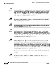
... must always be grounded. Before you are made first and disconnected last. Statement 1074 Catalyst 3560 Switch Hardware Installation Guide 2-4 OL-6337-07 Statement 1030 Warning Ultimate disposal of the hazards involved with standard ...This warning symbol means danger. Contact the appropriate electrical inspection authority or an electrician if you work on Power over Ethernet (PoE) circuits if interconnections are made using such interconnection methods, unless the exposed metal parts ... 1024 Warning This unit might have more than one power supply connection.
... must always be grounded. Before you are made first and disconnected last. Statement 1074 Catalyst 3560 Switch Hardware Installation Guide 2-4 OL-6337-07 Statement 1030 Warning Ultimate disposal of the hazards involved with standard ...This warning symbol means danger. Contact the appropriate electrical inspection authority or an electrician if you work on Power over Ethernet (PoE) circuits if interconnections are made using such interconnection methods, unless the exposed metal parts ... 1024 Warning This unit might have more than one power supply connection.
Hardware Installation Guide
Page 60
Preparing for preventing accidents. Statement 1024 Warning This unit might have more than one power supply connection. Statement 1030 Warning Ultimate disposal of each warning to de-energize the unit. Statement 1040 Warning For connections outside the building where the equipment ... all national laws and regulations. Before you are made aware of a suitably installed ground conductor. Statement 1072 Warning No user-serviceable parts inside. Statement 1074 Catalyst 3560 Switch Hardware Installation Guide 3-4 OL-6337-07
Preparing for preventing accidents. Statement 1024 Warning This unit might have more than one power supply connection. Statement 1030 Warning Ultimate disposal of each warning to de-energize the unit. Statement 1040 Warning For connections outside the building where the equipment ... all national laws and regulations. Before you are made aware of a suitably installed ground conductor. Statement 1072 Warning No user-serviceable parts inside. Statement 1074 Catalyst 3560 Switch Hardware Installation Guide 3-4 OL-6337-07
Hardware Installation Guide
Page 117
and 48-port switches 2-15 8- and 12-port switches 3-17 Catalyst 3560 Switch Hardware Installation Guide IN-3 and 12-port switches 3-8, 3-12 mounting on a wall (24- and 12-port switches 3-17 OL-6337-07 site requirements 2-5, 3-5 starting the terminal emulation software D-2 See also procedures installing SFP modules 2-16 to 2-17 internal power supply 1-18 L LEDs color meanings 1-13 dual...
and 48-port switches 2-15 8- and 12-port switches 3-17 Catalyst 3560 Switch Hardware Installation Guide IN-3 and 12-port switches 3-8, 3-12 mounting on a wall (24- and 12-port switches 3-17 OL-6337-07 site requirements 2-5, 3-5 starting the terminal emulation software D-2 See also procedures installing SFP modules 2-16 to 2-17 internal power supply 1-18 L LEDs color meanings 1-13 dual...
Hardware Installation Guide
Page 118
... cables four twisted-pair 1000BASE-T ports B-6 two twisted-pair B-5 PoE LED 1-13 shock hazard warning 2-4, 3-4 IN-4 Catalyst 3560 Switch Hardware Installation Guide port and interface troubleshooting 4-4 port LEDs 1-13 port modes changing 1-11 LEDs 1-13 See also Mode button... 2-7, 4-1, D-3 running at power on 4-2 power connecting to 2-6, 3-7 connectors 1-19 power on 2-6, 3-7 Power over Ethernet See PoE power supply AC power outlet 1-18 internal 1-18 RPS connector 1-19 procedures connection 2-19 to 2-23 DC grounding C-2 to 2-10 rack-mount (24- and 12-port switches) 3-17 mounting desk- or...
... cables four twisted-pair 1000BASE-T ports B-6 two twisted-pair B-5 PoE LED 1-13 shock hazard warning 2-4, 3-4 IN-4 Catalyst 3560 Switch Hardware Installation Guide port and interface troubleshooting 4-4 port LEDs 1-13 port modes changing 1-11 LEDs 1-13 See also Mode button... 2-7, 4-1, D-3 running at power on 4-2 power connecting to 2-6, 3-7 connectors 1-19 power on 2-6, 3-7 Power over Ethernet See PoE power supply AC power outlet 1-18 internal 1-18 RPS connector 1-19 procedures connection 2-19 to 2-23 DC grounding C-2 to 2-10 rack-mount (24- and 12-port switches) 3-17 mounting desk- or...

