
Installation Guide
Page 6
... Configuration 1-31 Large Campus Configuration 1-33 Installing and Starting Up the Switch 2-1 Preparing for Using the Switch 1-25 Small- Contents 2 C H A P T E R LEDs 1-11 System LED 1-14 RPS LED 1-15 Port LEDs and Modes 1-16 Rear-Panel Description 1-21 Power Connectors 1-22 Internal Power Supply Connector 1-23 Cisco RPS Connector 1-23 Console Port 1-24 Management Options 1-24 Network...
... Configuration 1-31 Large Campus Configuration 1-33 Installing and Starting Up the Switch 2-1 Preparing for Using the Switch 1-25 Small- Contents 2 C H A P T E R LEDs 1-11 System LED 1-14 RPS LED 1-15 Port LEDs and Modes 1-16 Rear-Panel Description 1-21 Power Connectors 1-22 Internal Power Supply Connector 1-23 Cisco RPS Connector 1-23 Console Port 1-24 Management Options 1-24 Network...

Installation Guide
Page 9
INDEX Grounded Equipment Warning C-23 Supply Circuit Warning C-24 No On/Off Switch Warning C-25 Power Supply Warning C-27 Work During Lightning Activity Warning C-30 Product Disposal Warning C-31 Chassis Warning-Rack-Mounting and Servicing C-33 Chassis Power Connection Warning C-38 Shock Hazard from Interconnections Warning C-41 Contents 78-6456-03 Catalyst 3500 Series XL Hardware Installation Guide ix
INDEX Grounded Equipment Warning C-23 Supply Circuit Warning C-24 No On/Off Switch Warning C-25 Power Supply Warning C-27 Work During Lightning Activity Warning C-30 Product Disposal Warning C-31 Chassis Warning-Rack-Mounting and Servicing C-33 Chassis Power Connection Warning C-38 Shock Hazard from Interconnections Warning C-41 Contents 78-6456-03 Catalyst 3500 Series XL Hardware Installation Guide ix

Installation Guide
Page 27
... Analyzer (SPAN) port monitoring on any port • Support for command switch redundancy • Support for optional Cisco 600W Redundant Power System (RPS) that operates on AC input and supplies DC output to four 1000BaseZX GBICs with the Catalyst 3508G XL switch) Management • Cisco IOS command-line interface (CLI) through the console port or Telnet •...
... Analyzer (SPAN) port monitoring on any port • Support for command switch redundancy • Support for optional Cisco 600W Redundant Power System (RPS) that operates on AC input and supplies DC output to four 1000BaseZX GBICs with the Catalyst 3508G XL switch) Management • Cisco IOS command-line interface (CLI) through the console port or Telnet •...

Installation Guide
Page 29
... 1-5, and Figure 1-6) have a set of LEDs and a Mode button. (The Catalyst 3548 XL switch has a Mode label that operates on AC input and supplies DC output to the Catalyst 3524-PWR XL switch Inline Power (Catalyst 3524-PWR XL switch only) • Ability to provide inline power for Cisco IP Phones from all 24 10/100 Ethernet ports • Auto...
... 1-5, and Figure 1-6) have a set of LEDs and a Mode button. (The Catalyst 3548 XL switch has a Mode label that operates on AC input and supplies DC output to the Catalyst 3524-PWR XL switch Inline Power (Catalyst 3524-PWR XL switch only) • Ability to provide inline power for Cisco IP Phones from all 24 10/100 Ethernet ports • Auto...

Installation Guide
Page 39
...functioning properly. Note The Cisco RPS 300 (model PWR300-AC-RPS) supports the Catalyst 3524-PWR XL switch. 78-6456-04 Catalyst 3500 Series XL Hardware Installation Guide 1-15 If the switch power supply fails, the switch powers down , or a fan on the bottom of the power supplies in the RPS could ...Front-Panel Description RPS LED The Redundant Power System (RPS) LED shows the RPS status. Note The Cisco RPS 600 (model PWR600-AC-RPS) supports the Catalyst 3512, 3524, 3548, and 3508 XL switches. RPS and the switch AC power supply are using power from the RPS. For more information ...
...functioning properly. Note The Cisco RPS 300 (model PWR300-AC-RPS) supports the Catalyst 3524-PWR XL switch. 78-6456-04 Catalyst 3500 Series XL Hardware Installation Guide 1-15 If the switch power supply fails, the switch powers down , or a fan on the bottom of the power supplies in the RPS could ...Front-Panel Description RPS LED The Redundant Power System (RPS) LED shows the RPS status. Note The Cisco RPS 600 (model PWR600-AC-RPS) supports the Catalyst 3512, 3524, 3548, and 3508 XL switches. RPS and the switch AC power supply are using power from the RPS. For more information ...

Installation Guide
Page 40
... could have failed. One of the switch is down , or a fan on the RPS could be powered down , and redundancy is operating on the Cisco RPS 300, refer to interpret the port LED colors after you change the port mode. Internal power supply of the power supplies in the Catalyst 3548 XL switch, press the Mode label. Port LEDs...
... could have failed. One of the switch is down , or a fan on the RPS could be powered down , and redundancy is operating on the Cisco RPS 300, refer to interpret the port LED colors after you change the port mode. Internal power supply of the power supplies in the Catalyst 3548 XL switch, press the Mode label. Port LEDs...

Installation Guide
Page 45
...-6456-04 CONSOLE DC INPUTS FOR REMOTE POWER SUPPLY SPECIFIED IN MANUAL. +5V @24A, +12V @.5A RJ-45 console port Redundant power system connector Fans Catalyst 3500 Series XL Hardware Installation Guide 1-21 Chapter 1 Product Overview Rear-Panel Description Rear-Panel Description Switch rear panels have an AC power connector, an RPS connector, and an RJ...
...-6456-04 CONSOLE DC INPUTS FOR REMOTE POWER SUPPLY SPECIFIED IN MANUAL. +5V @24A, +12V @.5A RJ-45 console port Redundant power system connector Fans Catalyst 3500 Series XL Hardware Installation Guide 1-21 Chapter 1 Product Overview Rear-Panel Description Rear-Panel Description Switch rear panels have an AC power connector, an RPS connector, and an RJ...

Installation Guide
Page 46
...~ 1.6A/0.9A 50-60HZ DC INPUTS FOR REMOTE POWER SUPPLY SPECIFIED IN MANUAL +3.3V @17A, +12 @1.1A CONSOLE AC power connector Fan exhaust RJ-45 console port Redundant power system connector Power Connectors You can provide power to the switch either through the internal power supply or through the Cisco RPS. 1-22 Catalyst 3500 Series XL Hardware Installation Guide 78-6456...
...~ 1.6A/0.9A 50-60HZ DC INPUTS FOR REMOTE POWER SUPPLY SPECIFIED IN MANUAL +3.3V @17A, +12 @1.1A CONSOLE AC power connector Fan exhaust RJ-45 console port Redundant power system connector Power Connectors You can provide power to the switch either through the internal power supply or through the Cisco RPS. 1-22 Catalyst 3500 Series XL Hardware Installation Guide 78-6456...

Installation Guide
Page 47
... Description Internal Power Supply Connector The internal power supply is not recommended. If you plan to use the internal power supply, use up to 150W DC each external device. Cisco RPS Connector Specific Cisco RPS models support specific Catalyst 3500 XL switches: • Cisco RPS 600 (model PWR600-AC-RPS)-Supports the Catalyst 3512, 3524, 3548, and 3508 XL switches • Cisco RPS 300...
... Description Internal Power Supply Connector The internal power supply is not recommended. If you plan to use the internal power supply, use up to 150W DC each external device. Cisco RPS Connector Specific Cisco RPS models support specific Catalyst 3500 XL switches: • Cisco RPS 600 (model PWR600-AC-RPS)-Supports the Catalyst 3512, 3524, 3548, and 3508 XL switches • Cisco RPS 300...

Installation Guide
Page 48
... to the Cisco IOS Desktop Switching Software Configuration Guide and the online help for up of four web-based applications that adapter from Cisco. For more information, refer to the RPS receptacle. It automatically senses when one of the console port and the supplied rollover cable and...78-6456-04 You can connect a Catalyst 3500 XL switch to six switches. For more than one switch at the same time, the subsequent switches will not be powered. Management Options Chapter 1 Product Overview RPS Connector on the Catalyst 3524-PWR XL Switch The Cisco RPS 300 (model PWR300-AC-RPS...
... to the Cisco IOS Desktop Switching Software Configuration Guide and the online help for up of four web-based applications that adapter from Cisco. For more information, refer to the RPS receptacle. It automatically senses when one of the console port and the supplied rollover cable and...78-6456-04 You can connect a Catalyst 3500 XL switch to six switches. For more than one switch at the same time, the subsequent switches will not be powered. Management Options Chapter 1 Product Overview RPS Connector on the Catalyst 3524-PWR XL Switch The Cisco RPS 300 (model PWR300-AC-RPS...

Installation Guide
Page 61
...Warning To prevent the switch from overheating, do not operate it last. Statement 51 Warning Unplug the power cord before you work with TN power systems. Statement 19 ...240 VAC, 10A international) is intended to be given to connecting units to the supply circuit so that exceeds the maximum recommended ambient temperature of clearance around the ventilation ...Statement 20 78-6456-04 Catalyst 3500 Series XL Hardware Installation Guide 2-3 Statement 17B Warning The device is not overloaded. Chapter 2 Installing and Starting Up the Switch Preparing for short-circuit (...
...Warning To prevent the switch from overheating, do not operate it last. Statement 51 Warning Unplug the power cord before you work with TN power systems. Statement 19 ...240 VAC, 10A international) is intended to be given to connecting units to the supply circuit so that exceeds the maximum recommended ambient temperature of clearance around the ventilation ...Statement 20 78-6456-04 Catalyst 3500 Series XL Hardware Installation Guide 2-3 Statement 17B Warning The device is not overloaded. Chapter 2 Installing and Starting Up the Switch Preparing for short-circuit (...
Installation Guide
Page 62
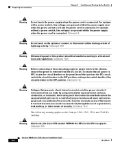
... that power is connected. For systems with a power switch, line voltages are present within the power supply even when the power switch is off and the power cord is connected. Avoid using uninsulated exposed metal contacts, conductors, or terminals. Statement 1072 The following warning applies to the Catalyst 3508, 3512, 3524, and 3548 XL switches: Warning Attach only the Cisco RPS...
... that power is connected. For systems with a power switch, line voltages are present within the power supply even when the power switch is off and the power cord is connected. Avoid using uninsulated exposed metal contacts, conductors, or terminals. Statement 1072 The following warning applies to the Catalyst 3508, 3512, 3524, and 3548 XL switches: Warning Attach only the Cisco RPS...
Installation Guide
Page 71
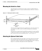
...8 DUPLX SPEED Phillips machine screws After the switch is connected, the System LED turns amber for installation instructions. After the power is mounted in the rack, attach the power cord to the left or right bracket. 78-6456-04 Catalyst 3500 Series XL Hardware Installation Guide 2-13 ...Cisco RPS, see the Cisco RPS documentation for 2 seconds, and then it flashes green while the switch completes the series of the switch and the other devices installed in the "Powering On the Switch and Running POST" section on page 2-17. If you are attached to the switch, use the supplied...
...8 DUPLX SPEED Phillips machine screws After the switch is connected, the System LED turns amber for installation instructions. After the power is mounted in the rack, attach the power cord to the left or right bracket. 78-6456-04 Catalyst 3500 Series XL Hardware Installation Guide 2-13 ...Cisco RPS, see the Cisco RPS documentation for 2 seconds, and then it flashes green while the switch completes the series of the switch and the other devices installed in the "Powering On the Switch and Running POST" section on page 2-17. If you are attached to the switch, use the supplied...
Installation Guide
Page 74
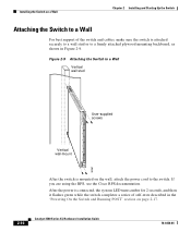
... flashes green while the switch completes a series of the switch and cables, make sure the switch is mounted on the wall, attach the power cord to the switch. Installing the Switch on page 2-17. 2-16 Catalyst 3500 Series XL Hardware Installation Guide 78-6456-04 Figure 2-9 Attaching the Switch to a Wall Vertical wall stud 8 User-supplied screws 7 6 5 4 3 2 Vertical wall...
... flashes green while the switch completes a series of the switch and cables, make sure the switch is mounted on the wall, attach the power cord to the switch. Installing the Switch on page 2-17. 2-16 Catalyst 3500 Series XL Hardware Installation Guide 78-6456-04 Figure 2-9 Attaching the Switch to a Wall Vertical wall stud 8 User-supplied screws 7 6 5 4 3 2 Vertical wall...
Installation Guide
Page 82
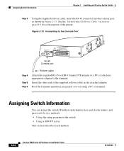
... INPUTS FOR REMOTE POWER SUPPLY SPECIFIED IN MANUAL. +5V @24A, +12V @1.0A RJ-45 Console port Step 4 Step 5 Step 6 Rollover cable Attach the supplied RJ-45-to-DB-9 female DTE adapter to a PC or attach an appropriate adapter to the terminal. Assigning Switch Information Chapter 2 ...PC or terminal. Assigning Switch Information You can assign the switch IP address information, host and cluster names, and passwords by two methods: • Using the setup program in the switch • Using a BOOTP server This section describes each method. 2-24 Catalyst 3500 Series XL Hardware ...
... INPUTS FOR REMOTE POWER SUPPLY SPECIFIED IN MANUAL. +5V @24A, +12V @1.0A RJ-45 Console port Step 4 Step 5 Step 6 Rollover cable Attach the supplied RJ-45-to-DB-9 female DTE adapter to a PC or attach an appropriate adapter to the terminal. Assigning Switch Information Chapter 2 ...PC or terminal. Assigning Switch Information You can assign the switch IP address information, host and cluster names, and passwords by two methods: • Using the setup program in the switch • Using a BOOTP server This section describes each method. 2-24 Catalyst 3500 Series XL Hardware ...
Installation Guide
Page 137
Appendix C Translated Safety Warnings Power Supply Warning 78-6456-04 Catalyst 3500 Series XL Hardware Installation Guide C-29
Appendix C Translated Safety Warnings Power Supply Warning 78-6456-04 Catalyst 3500 Series XL Hardware Installation Guide C-29
Installation Guide
Page 157
... 2-24 installation 2-7 to 2-17 IP address 2-24 product disposal warning C-31 PSTN 1-33 publications, related xviii Public Switched Telephone Network See PSTN Q qualified personnel warning C-7 R rack installation 2-9 bracket mounting points 2-10 rack-mounting 2-13 rear panel 1-21 to 1-22 clearance 2-8 Redundant Power Supply 78-6456-04 Catalyst 3500 Series XL Hardware Installation Guide IN-5
... 2-24 installation 2-7 to 2-17 IP address 2-24 product disposal warning C-31 PSTN 1-33 publications, related xviii Public Switched Telephone Network See PSTN Q qualified personnel warning C-7 R rack installation 2-9 bracket mounting points 2-10 rack-mounting 2-13 rear panel 1-21 to 1-22 clearance 2-8 Redundant Power Supply 78-6456-04 Catalyst 3500 Series XL Hardware Installation Guide IN-5
Installation Guide
Page 158
... Manager 1-25 supply circuit warning C-24 switch applications 1-25 startup powering on 2-17 system LED 1-14 T table-mounting 2-17 technical specifications A-1 Telnet, and accessing the CLI 1-25 temperature operating A-1 warning C-16 terminal, connecting to switch 2-23 terminal emulation software 2-23 TN power warning C-19 translated warnings C-1 troubleshooting 3-1 to 3-5 U UTL LED 1-16, 1-17 IN-6 Catalyst 3500 Series...
... Manager 1-25 supply circuit warning C-24 switch applications 1-25 startup powering on 2-17 system LED 1-14 T table-mounting 2-17 technical specifications A-1 Telnet, and accessing the CLI 1-25 temperature operating A-1 warning C-16 terminal, connecting to switch 2-23 terminal emulation software 2-23 TN power warning C-19 translated warnings C-1 troubleshooting 3-1 to 3-5 U UTL LED 1-16, 1-17 IN-6 Catalyst 3500 Series...

