
Hardware Installation Guide
Page 2
...B digital devices. Catalyst 3560 Switch Hardware Installation Guide © 2004-2010 Cisco Systems, Inc. If...Cisco Eos, Cisco Explorer, Cisco HealthPresence, Cisco IronPort, the Cisco logo, Cisco Nurse Connect, Cisco Pulse, Cisco SensorBase, Cisco StackPower, Cisco StadiumVision, Cisco TelePresence, Cisco TrustSec, Cisco Unified Computing System, Cisco WebEx, DCE, Flip Channels, Flip for a Class A digital device, pursuant to correct the interference at your right to use of the FCC rules. and Access Registrar, Aironet, AllTouch, AsyncOS, Bringing the Meeting To You, Catalyst...
...B digital devices. Catalyst 3560 Switch Hardware Installation Guide © 2004-2010 Cisco Systems, Inc. If...Cisco Eos, Cisco Explorer, Cisco HealthPresence, Cisco IronPort, the Cisco logo, Cisco Nurse Connect, Cisco Pulse, Cisco SensorBase, Cisco StackPower, Cisco StadiumVision, Cisco TelePresence, Cisco TrustSec, Cisco Unified Computing System, Cisco WebEx, DCE, Flip Channels, Flip for a Class A digital device, pursuant to correct the interference at your right to use of the FCC rules. and Access Registrar, Aironet, AllTouch, AsyncOS, Bringing the Meeting To You, Catalyst...
Hardware Installation Guide
Page 7
...cisco.com/web/learning/index.html Purpose This guide describes the hardware features of Ethernet and local area networking. Conventions This document uses these areas, learning opportunities including training courses, self-study options, seminars, and career certifications programs are familiar with the concepts and terminology of the Catalyst 3560 switch... conventions and symbols for installing the Catalyst 3560 switch, hereafter known as the switch. Caution Means reader be careful. We assume that you are available on the Cisco.com Product Documentation home page. In...
...cisco.com/web/learning/index.html Purpose This guide describes the hardware features of Ethernet and local area networking. Conventions This document uses these areas, learning opportunities including training courses, self-study options, seminars, and career certifications programs are familiar with the concepts and terminology of the Catalyst 3560 switch... conventions and symbols for installing the Catalyst 3560 switch, hereafter known as the switch. Caution Means reader be careful. We assume that you are available on the Cisco.com Product Documentation home page. In...
Hardware Installation Guide
Page 8
...Use the statement number provided at the end of the hazards involved with electrical circuitry and be familiar with Cisco Network Assistant • Release Notes for Cisco Network Assistant • Cisco Small Form-Factor Pluggable Modules Installation Notes • Cisco CWDM GBIC and CWDM SFP Installation Note • Cisco... on Cisco.com for the latest information. • Catalyst 3560 Switch Software Configuration Guide • Catalyst 3560 Switch Command Reference • Catalyst 3750, 3560, 3550, 2970, and 2960 Switch System Message Guide • Catalyst 3560 Switch Getting Started...
...Use the statement number provided at the end of the hazards involved with electrical circuitry and be familiar with Cisco Network Assistant • Release Notes for Cisco Network Assistant • Cisco Small Form-Factor Pluggable Modules Installation Notes • Cisco CWDM GBIC and CWDM SFP Installation Note • Cisco... on Cisco.com for the latest information. • Catalyst 3560 Switch Software Configuration Guide • Catalyst 3560 Switch Command Reference • Catalyst 3750, 3560, 3550, 2970, and 2960 Switch System Message Guide • Catalyst 3560 Switch Getting Started...
Hardware Installation Guide
Page 9
The RSS feeds are a free service and Cisco currently supports RSS version 2.0. OL-6337-07 Catalyst 3560 Switch Hardware Installation Guide ix Preface Obtaining Documentation and Submitting a Service Request • Cisco Small Form-Factor Pluggable Modules Compatibility Matrix • Compatibility Matrix for 1000BASE...service request, and gathering additional information, see the monthly What's New in Cisco Product Documentation, which also lists all new and revised Cisco technical documentation, at: http://www.cisco.com/en/US/docs/general/whatsnew/whatsnew.html Subscribe to the What's New...
The RSS feeds are a free service and Cisco currently supports RSS version 2.0. OL-6337-07 Catalyst 3560 Switch Hardware Installation Guide ix Preface Obtaining Documentation and Submitting a Service Request • Cisco Small Form-Factor Pluggable Modules Compatibility Matrix • Compatibility Matrix for 1000BASE...service request, and gathering additional information, see the monthly What's New in Cisco Product Documentation, which also lists all new and revised Cisco technical documentation, at: http://www.cisco.com/en/US/docs/general/whatsnew/whatsnew.html Subscribe to the What's New...

Hardware Installation Guide
Page 11
... Catalyst 3560 switch. The Catalyst 3560-8PC and the Catalyst 3560-12PC-S compact switches provide the same Power over Ethernet (PoE) connectivity and can connect devices like workstations, Cisco Wireless Access Points, Cisco IP Phones, and other network devices such as servers, routers, and other network devices. See the switch software configuration guide for instructions on how to use...
... Catalyst 3560 switch. The Catalyst 3560-8PC and the Catalyst 3560-12PC-S compact switches provide the same Power over Ethernet (PoE) connectivity and can connect devices like workstations, Cisco Wireless Access Points, Cisco IP Phones, and other network devices such as servers, routers, and other network devices. See the switch software configuration guide for instructions on how to use...

Hardware Installation Guide
Page 15
...page 1-19. For more information on the dual-purpose port, see the "Console Port" section on the switch are grouped in Figure 1-4. The first member of the Catalyst 3560-8PC switch and the Catalyst 3560-12PC-S switch (Figure 1-5 and Figure 1-6). The SFP module slots are on the front panel of the pair (port 1)... section on the left, as shown in pairs. The dual-purpose port can use either an RJ-45 connector or an SFP module, but not both at the same time. Figure 1-4 Catalyst 3560-48TS-S and 3560V2-48TS Switch Front Panel 126807 SYST RPS STAT DUPLX SPEED MODE 1 1X 2X 23 45 ...
...page 1-19. For more information on the dual-purpose port, see the "Console Port" section on the switch are grouped in Figure 1-4. The first member of the Catalyst 3560-8PC switch and the Catalyst 3560-12PC-S switch (Figure 1-5 and Figure 1-6). The SFP module slots are on the front panel of the pair (port 1)... section on the left, as shown in pairs. The dual-purpose port can use either an RJ-45 connector or an SFP module, but not both at the same time. Figure 1-4 Catalyst 3560-48TS-S and 3560V2-48TS Switch Front Panel 126807 SYST RPS STAT DUPLX SPEED MODE 1 1X 2X 23 45 ...

Hardware Installation Guide
Page 18
...service people who are authorized within 328 feet (100 meters). Avoid using uninsulated exposed metal contacts, conductors, or terminals. Front Panel Description Chapter 1 Product Overview The 10/100/1000 ports on the Catalyst 3560G-48TS switch are grouped in Figure 1-10. Port 3 is 1000 Mb/s....must be accessed only through the use Category 3 or Category 4 cables. Statement 1072 • 100BASE-TX and 1000BASE-T traffic requires Category 5 cable. 10BASE-T traffic can configure duplex mode to 10 or 100 Mb/s. Figure 1-10 Catalyst 3560G-48TS Switch Front Panel 119675 SYST RPS STAT ...
...service people who are authorized within 328 feet (100 meters). Avoid using uninsulated exposed metal contacts, conductors, or terminals. Front Panel Description Chapter 1 Product Overview The 10/100/1000 ports on the Catalyst 3560G-48TS switch are grouped in Figure 1-10. Port 3 is 1000 Mb/s....must be accessed only through the use Category 3 or Category 4 cables. Statement 1072 • 100BASE-TX and 1000BASE-T traffic requires Category 5 cable. 10BASE-T traffic can configure duplex mode to 10 or 100 Mb/s. Figure 1-10 Catalyst 3560G-48TS Switch Front Panel 119675 SYST RPS STAT ...

Hardware Installation Guide
Page 19
... came with IEEE 802.3af and Cisco prestandard PoE support for Cisco IP Phones and Cisco Aironet Access Points. • Each of the Catalyst 3560-8PC, 3560-12PC-S, 3560-24PS, and 3560V2-24PS switch 10/100 ports or the Catalyst 3560G-24PS switch 10/100/1000 ports deliver up to... a maximum power output of approximately 125 W total PoE power. • On a per-port basis, you can use...
... came with IEEE 802.3af and Cisco prestandard PoE support for Cisco IP Phones and Cisco Aironet Access Points. • Each of the Catalyst 3560-8PC, 3560-12PC-S, 3560-24PS, and 3560V2-24PS switch 10/100 ports or the Catalyst 3560G-24PS switch 10/100/1000 ports deliver up to... a maximum power output of approximately 125 W total PoE power. • On a per-port basis, you can use...

Hardware Installation Guide
Page 20
... 126809 The SFP module patch cable can use the SFP modules specified in an SFP module slot. However, you must use the media-type interface configuration command to other Catalyst series switches, you can connect only two Catalyst 3560 switches. Each uplink port has two LEDs. ... Product Overview Many legacy powered devices, including older Cisco IP phones and access points that first links up. To connect a Catalyst 3560 switch to select the RJ-45 connector or the SFP module connector. SFP Modules The switch uses Gigabit Ethernet SFP modules to a copper SFP module....
... 126809 The SFP module patch cable can use the SFP modules specified in an SFP module slot. However, you must use the media-type interface configuration command to other Catalyst series switches, you can connect only two Catalyst 3560 switches. Each uplink port has two LEDs. ... Product Overview Many legacy powered devices, including older Cisco IP phones and access points that first links up. To connect a Catalyst 3560 switch to select the RJ-45 connector or the SFP module connector. SFP Modules The switch uses Gigabit Ethernet SFP modules to a copper SFP module....

Hardware Installation Guide
Page 21
... is not powered on. Chapter 1 Product Overview Front Panel Description LEDs You can use to select one of the port modes. System is not functioning properly. OL-6337-07 Catalyst 3560 Switch Hardware Installation Guide 1-11 Figure 1-12 Catalyst 3560 Switch LEDs SYST RPS STAT DUPLX SPEED PoE MODE 12345 67 8 12 1X 34 56...
... is not powered on. Chapter 1 Product Overview Front Panel Description LEDs You can use to select one of the port modes. System is not functioning properly. OL-6337-07 Catalyst 3560 Switch Hardware Installation Guide 1-11 Figure 1-12 Catalyst 3560 Switch LEDs SYST RPS STAT DUPLX SPEED PoE MODE 12345 67 8 12 1X 34 56...

Hardware Installation Guide
Page 24
... Mb/s in half-duplex mode. 1-14 Catalyst 3560 Switch Hardware Installation Guide OL-6337-07 Blinking green Port is not sending or receiving packets. Note When installed in Catalyst 3560 switches, 1000BASE-T SFP modules can be used to connect Cisco prestandard IP Phones or wireless access points or... IEEE 802.3af-compliant devices to the powered device will exceed the 370 W switch power capacity. The port LED is ...
... Mb/s in half-duplex mode. 1-14 Catalyst 3560 Switch Hardware Installation Guide OL-6337-07 Blinking green Port is not sending or receiving packets. Note When installed in Catalyst 3560 switches, 1000BASE-T SFP modules can be used to connect Cisco prestandard IP Phones or wireless access points or... IEEE 802.3af-compliant devices to the powered device will exceed the 370 W switch power capacity. The port LED is ...
Hardware Installation Guide
Page 25
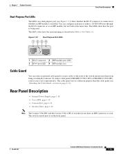
... guard serves a different purpose than the cable guide (see Figure 1-13) show how the port is being accidentally removed. OL-6337-07 Catalyst 3560 Switch Hardware Installation Guide 1-15 You can order an optional cable guard to secure cables to Table 1-6. Figure 1-13 Dual-Purpose Port LEDs 1 234... as described in Table 1-4 to the front of the switch and prevent them from being used. The LED colors have an RPS connector or a fan. To order a cable guard (CBLGRD-C3560-12PC or CBLGRD-C3560-8PC), contact your Cisco representative. The LEDs show whether the RJ-45 connector is...
... guard serves a different purpose than the cable guide (see Figure 1-13) show how the port is being accidentally removed. OL-6337-07 Catalyst 3560 Switch Hardware Installation Guide 1-15 You can order an optional cable guard to secure cables to Table 1-6. Figure 1-13 Dual-Purpose Port LEDs 1 234... as described in Table 1-4 to the front of the switch and prevent them from being used. The LED colors have an RPS connector or a fan. To order a cable guard (CBLGRD-C3560-12PC or CBLGRD-C3560-8PC), contact your Cisco representative. The LEDs show whether the RJ-45 connector is...
Hardware Installation Guide
Page 28
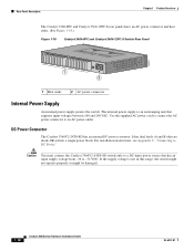
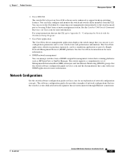
... 1-18.) Figure 1-18 Catalyst 3560-8PC and Catalyst 3560-12PC-S Switch Rear Panel 250607 1 2 1 Heat sinks 2 AC power connector Internal Power Supply An internal power supply powers the switch. For installation instructions, see Appendix C, "Connecting to an AC power outlet. Use the supplied AC power cord... to connect the AC power connector to DC Power." DC Power Connector The Catalyst 3560V2-24TS-SD has an internal ...
... 1-18.) Figure 1-18 Catalyst 3560-8PC and Catalyst 3560-12PC-S Switch Rear Panel 250607 1 2 1 Heat sinks 2 AC power connector Internal Power Supply An internal power supply powers the switch. For installation instructions, see Appendix C, "Connecting to an AC power outlet. Use the supplied AC power cord... to connect the AC power connector to DC Power." DC Power Connector The Catalyst 3560V2-24TS-SD has an internal ...

Hardware Installation Guide
Page 29
...or two failed switches at a time. Use the RPS connector cable supplied with the RPS to connect the RPS to the failed switch, preventing loss of network traffic. If you want to connect the switch console port to a terminal, you can connect the switch to either ...when the internal power supply of a connected switch fails and provides power to the Catalyst 3560V2-24TS-SD switch, the switch is 675 W. For complete information about the Cisco RPS products, including compatibility matrixes listing the supported RPS for each Catalyst 3560 switch, see the "Connector and Cable Specifications" ...
...or two failed switches at a time. Use the RPS connector cable supplied with the RPS to connect the RPS to the failed switch, preventing loss of network traffic. If you want to connect the switch console port to a terminal, you can connect the switch to either ...when the internal power supply of a connected switch fails and provides power to the Catalyst 3560V2-24TS-SD switch, the switch is 675 W. For complete information about the Cisco RPS products, including compatibility matrixes listing the supported RPS for each Catalyst 3560 switch, see the "Connector and Cable Specifications" ...

Hardware Installation Guide
Page 30
... instructions. Find the Network Assistant installer. Figure 1-19 Switch Left Panel 157824 1 1 Security slot Management Options The Catalyst 3560 switches offer several management options: • Device manager You can access the device manager from Cisco.com and run on your network through a web browser. You can use the device manager in your PC. It offers...
... instructions. Find the Network Assistant installer. Figure 1-19 Switch Left Panel 157824 1 1 Security slot Management Options The Catalyst 3560 switches offer several management options: • Device manager You can access the device manager from Cisco.com and run on your network through a web browser. You can use the device manager in your PC. It offers...
Hardware Installation Guide
Page 31
... platforms such as HP OpenView or SunNet Manager. The CiscoView application, which you can use the CLI, go to Appendix D, "Configuring the Switch with your management station directly to support desktop-switching features. See the Catalyst 3560 Switch Command Reference on Cisco.com for more information. • SNMP network management You can fully configure and monitor...
... platforms such as HP OpenView or SunNet Manager. The CiscoView application, which you can use the CLI, go to Appendix D, "Configuring the Switch with your management station directly to support desktop-switching features. See the Catalyst 3560 Switch Command Reference on Cisco.com for more information. • SNMP network management You can fully configure and monitor...
Hardware Installation Guide
Page 34
... chassis. they contain electromagnetic interference (EMI) that no exposed portion of the switch. Be sure that might disrupt other equipment. Statement 378 Catalyst 3560 Switch Hardware Installation Guide 2-2 OL-6337-07 Failure to use the correct hardware or to power lines, remove jewelry (including rings, necklaces...place. To prevent airflow restriction, allow at least 3 inches (7.6 cm) of electricity. Statement 265 Warning Attach only the following Cisco RPS model to the terminals. Statement 43 Warning Do not stack the chassis on the back of the DC-input power source ...
... chassis. they contain electromagnetic interference (EMI) that no exposed portion of the switch. Be sure that might disrupt other equipment. Statement 378 Catalyst 3560 Switch Hardware Installation Guide 2-2 OL-6337-07 Failure to use the correct hardware or to power lines, remove jewelry (including rings, necklaces...place. To prevent airflow restriction, allow at least 3 inches (7.6 cm) of electricity. Statement 265 Warning Attach only the following Cisco RPS model to the terminals. Statement 43 Warning Do not stack the chassis on the back of the DC-input power source ...

Hardware Installation Guide
Page 35
... if it serves as the main disconnecting device. Statement 1019 Warning A readily accessible two-poled disconnect device must be accessed only through the use of a special tool, lock and key, or other means of security. Statement 1006 Warning Class 1 laser product. A restricted access area...This unit is the only unit in the rack. • When mounting this unit in the rack. Statement 1022 OL-6337-07 Catalyst 3560 Switch Hardware Installation Guide 2-3 Statement 1003 Warning Read the installation instructions before mounting or servicing the unit in a rack, you must be...
... if it serves as the main disconnecting device. Statement 1019 Warning A readily accessible two-poled disconnect device must be accessed only through the use of a special tool, lock and key, or other means of security. Statement 1006 Warning Class 1 laser product. A restricted access area...This unit is the only unit in the rack. • When mounting this unit in the rack. Statement 1022 OL-6337-07 Catalyst 3560 Switch Hardware Installation Guide 2-3 Statement 1003 Warning Read the installation instructions before mounting or servicing the unit in a rack, you must be...

Hardware Installation Guide
Page 36
...device. A restricted access area can be grounded. Statement 1074 Catalyst 3560 Switch Hardware Installation Guide 2-4 OL-6337-07 Statement 1040 Warning For connections outside the building where the equipment is available. Use the statement number provided at the end of each warning to... danger. Statement 1071 Warning Voltages that accompanied this equipment. Before you are uncertain that could cause bodily injury. Avoid using uninsulated exposed metal contacts, conductors, or terminals. Statement 1044 Warning When installing or replacing the unit, the ground connection...
...device. A restricted access area can be grounded. Statement 1074 Catalyst 3560 Switch Hardware Installation Guide 2-4 OL-6337-07 Statement 1040 Warning For connections outside the building where the equipment is available. Use the statement number provided at the end of each warning to... danger. Statement 1071 Warning Voltages that accompanied this equipment. Before you are uncertain that could cause bodily injury. Avoid using uninsulated exposed metal contacts, conductors, or terminals. Statement 1044 Warning When installing or replacing the unit, the ground connection...

Hardware Installation Guide
Page 37
...AC power receptacle. • Temperature around the unit does not exceed 113°F (45°C). If the switch is DC-isolated (DC-I). Catalyst 3560 switch SFP ports use shorter lengths of this product is installed in Table B-1 on page B-4, which lists the cable specifications for 1000BASE...to intrabuilding or nonexposed wiring or cabling. When you use both GLC-GE-100XX and GLC-FE-100XX SFP modules. and 48-Port Switches) Statement 371-Power Cable and AC Adapter Preparing for the Catalyst 3560 switch. Chapter 2 Switch Installation (24- Access to avoid overloading the receiver. ...
...AC power receptacle. • Temperature around the unit does not exceed 113°F (45°C). If the switch is DC-isolated (DC-I). Catalyst 3560 switch SFP ports use shorter lengths of this product is installed in Table B-1 on page B-4, which lists the cable specifications for 1000BASE...to intrabuilding or nonexposed wiring or cabling. When you use both GLC-GE-100XX and GLC-FE-100XX SFP modules. and 48-Port Switches) Statement 371-Power Cable and AC Adapter Preparing for the Catalyst 3560 switch. Chapter 2 Switch Installation (24- Access to avoid overloading the receiver. ...

