
Supervisor Guide
Page 30
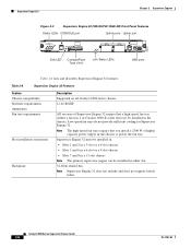
... MODE switch PCMCIA slot RESET button Switch load 1000BASE-X GBIC display Uplink Ports Switch Load 100% 1% PORT 1 LINK PORT 2 LINK LINK LEDs 44312 Table 2-2 lists and describes Supervisor Engine 2 features Table 2-2 Supervisor Engine 2 Features Feature Chassis compatibility Software requirements (minimum) Fan tray requirements Slot installation restrictions Backplane Hardware restrictions Description Supported on all Catalyst 6500...
... MODE switch PCMCIA slot RESET button Switch load 1000BASE-X GBIC display Uplink Ports Switch Load 100% 1% PORT 1 LINK PORT 2 LINK LINK LEDs 44312 Table 2-2 lists and describes Supervisor Engine 2 features Table 2-2 Supervisor Engine 2 Features Feature Chassis compatibility Software requirements (minimum) Fan tray requirements Slot installation restrictions Backplane Hardware restrictions Description Supported on all Catalyst 6500...

Supervisor Guide
Page 34
.... • Orange-The port is disabled. • Red-The supervisor engine is resetting; The VTT module terminates signals on the Catalyst switching bus. 2. the supervisor engine does not come online. • Off-The port is not active or the link is a VTT... = voltage termination module. Catalyst 6500 Series Supervisor Engine Guide 2-6 OL-7397-03 an overtemperature condition has occurred. PCMCIA Green-The installed Flash PC card is being accessed and is operational, the switch load bar meter indicates (as an approximate percentage) the current traffic load over the backplane.
.... • Orange-The port is disabled. • Red-The supervisor engine is resetting; The VTT module terminates signals on the Catalyst switching bus. 2. the supervisor engine does not come online. • Off-The port is not active or the link is a VTT... = voltage termination module. Catalyst 6500 Series Supervisor Engine Guide 2-6 OL-7397-03 an overtemperature condition has occurred. PCMCIA Green-The installed Flash PC card is being accessed and is operational, the switch load bar meter indicates (as an approximate percentage) the current traffic load over the backplane.
Supervisor Guide
Page 36
... fan trays require that a high-speed fan tray (either slot. 32-Gbps shared bus. Note Supervisor Engine 32 does not include and does not support switch fabric. Supervisor Engine 32 must be installed in: • Slots 1 and 2 in a 3-slot or a 4-slot chassis • Slots 5 and 6... 32. Table 2-6 Supervisor Engine 32 Features Feature Chassis compatibility Software requirements (minimum) Fan tray requirements Slot installation restrictions Backplane Description Supported on all Catalyst 6500 series chassis. 12.2(18)SXF All versions of Supervisor Engine 32 require that you install a 2500 W or ...
... fan trays require that a high-speed fan tray (either slot. 32-Gbps shared bus. Note Supervisor Engine 32 does not include and does not support switch fabric. Supervisor Engine 32 must be installed in: • Slots 1 and 2 in a 3-slot or a 4-slot chassis • Slots 5 and 6... 32. Table 2-6 Supervisor Engine 32 Features Feature Chassis compatibility Software requirements (minimum) Fan tray requirements Slot installation restrictions Backplane Description Supported on all Catalyst 6500 series chassis. 12.2(18)SXF All versions of Supervisor Engine 32 require that you install a 2500 W or ...

Supervisor Guide
Page 43
... The primary supervisor engine can be installed in either a fan tray 2 or Catalyst 6500-E series fan tray) be installed in the chassis to power the fan tray. OL-7397-03 Catalyst 6500 Series Supervisor Engine Guide 2-15 Note The high-speed fan trays require that... Engine 32 PISA does not include and does not support switch fabric. Table 2-10 Supervisor Engine 32 PISA Features Feature Chassis compatibility Software requirements (minimum) Fan tray requirements Slot installation restrictions Backplane Description Supported on all Catalyst 6500 series chassis. • WS-S32-GE-PISA-12...
... The primary supervisor engine can be installed in either a fan tray 2 or Catalyst 6500-E series fan tray) be installed in the chassis to power the fan tray. OL-7397-03 Catalyst 6500 Series Supervisor Engine Guide 2-15 Note The high-speed fan trays require that... Engine 32 PISA does not include and does not support switch fabric. Table 2-10 Supervisor Engine 32 PISA Features Feature Chassis compatibility Software requirements (minimum) Fan tray requirements Slot installation restrictions Backplane Description Supported on all Catalyst 6500 series chassis. • WS-S32-GE-PISA-12...

Supervisor Guide
Page 50
... Engine 720 Features Feature Chassis compatibility Software requirements (minimum) Fan tray requirements Slot installation restrictions Backplane Hardware restrictions Memory Switch Processor DRAM Route Processor DRAM Switch Processor Bootflash/Bootdisk Route Processor Bootflash CompactFlash (disk0) Description Supported on all Catalyst 6500 series chassis. • Supervisor Engine 720-12.2(14)SX • Supervisor Engine 720-3B...
... Engine 720 Features Feature Chassis compatibility Software requirements (minimum) Fan tray requirements Slot installation restrictions Backplane Hardware restrictions Memory Switch Processor DRAM Route Processor DRAM Switch Processor Bootflash/Bootdisk Route Processor Bootflash CompactFlash (disk0) Description Supported on all Catalyst 6500 series chassis. • Supervisor Engine 720-12.2(14)SX • Supervisor Engine 720-3B...
Supervisor Guide
Page 55
... Engine 720-10GE Features Feature Chassis compatibility Software requirements (minimum) Fan tray requirements Slot installation restrictions Backplane Hardware restrictions Description Supported on all Catalyst 6500 series chassis. 12.2(33)SHX Note If there are no DFC-equipped modules installed, certain configurations...Supervisor Engine 720-10GE require that a high-speed fan tray (either slot. 32-Gbps shared bus Integrated 720-Gbps Switch Fabric There are no additional hardware restrictions for Supervisor Engine 720-10GE. Refer to your software release notes for Supervisor Engine...
... Engine 720-10GE Features Feature Chassis compatibility Software requirements (minimum) Fan tray requirements Slot installation restrictions Backplane Hardware restrictions Description Supported on all Catalyst 6500 series chassis. 12.2(33)SHX Note If there are no DFC-equipped modules installed, certain configurations...Supervisor Engine 720-10GE require that a high-speed fan tray (either slot. 32-Gbps shared bus Integrated 720-Gbps Switch Fabric There are no additional hardware restrictions for Supervisor Engine 720-10GE. Refer to your software release notes for Supervisor Engine...

Supervisor Guide
Page 70
... The supervisor engines must be emitted from disconnected fibers or connectors. Slots 1 and 2 for the supervisor engine. Do not directly touch the backplane with your hand or any metal tool, or you are required to install a supervisor engine in the chassis: • Small flat-blade ... instruments. Note If you could shock yourself. Do not directly touch the backplane with your hand or any metal tool, or you could shock yourself. Slots 1 and 2 for instructions. and 4-slot chassis Catalyst 6500 Series Supervisor Engine Guide 3-2 OL-7397-03 Statement 93 Warning Invisible...
... The supervisor engines must be emitted from disconnected fibers or connectors. Slots 1 and 2 for the supervisor engine. Do not directly touch the backplane with your hand or any metal tool, or you are required to install a supervisor engine in the chassis: • Small flat-blade ... instruments. Note If you could shock yourself. Do not directly touch the backplane with your hand or any metal tool, or you could shock yourself. Slots 1 and 2 for instructions. and 4-slot chassis Catalyst 6500 Series Supervisor Engine Guide 3-2 OL-7397-03 Statement 93 Warning Invisible...

Supervisor Guide
Page 74
Installing a Supervisor Engine Chapter 3 Installing Supervisor Engines c. e. Catalyst 6500 Series Supervisor Engine Guide 3-6 OL-7397-03 Note Failure to create a small 0.040 inch (1 mm) gap between the module EMI gasket and the module ... thumb and forefinger of each hand, grasp the two ejector levers and gently press down to fully seat the supervisor engine in the backplane connector can result in the backplane connector. While gently pressing down 3 4 4 5 1mm Gap between the supervisor engine's EMI gasket and the module or cover plate above it . (See...
Installing a Supervisor Engine Chapter 3 Installing Supervisor Engines c. e. Catalyst 6500 Series Supervisor Engine Guide 3-6 OL-7397-03 Note Failure to create a small 0.040 inch (1 mm) gap between the module EMI gasket and the module ... thumb and forefinger of each hand, grasp the two ejector levers and gently press down to fully seat the supervisor engine in the backplane connector can result in the backplane connector. While gently pressing down 3 4 4 5 1mm Gap between the supervisor engine's EMI gasket and the module or cover plate above it . (See...

Supervisor Guide
Page 76
Note Make sure that the supervisor engine STATUS LED is lit. Periodically check the STATUS LED: Catalyst 6500 Series Supervisor Engine Guide 3-8 OL-7397-03 While gently pressing to the left 130911 o o INPUT OK FAN OUTPUT OK FAIL ...they are flush with the supervisor engine faceplate. Installing a Supervisor Engine Chapter 3 Installing Supervisor Engines Figure 3-4 Clearing the EMI Gasket in the backplane connector. Verify that the ejector levers are fully closed before tightening the captive installation screws. The ejector levers are fully closed when they will bend...
Note Make sure that the supervisor engine STATUS LED is lit. Periodically check the STATUS LED: Catalyst 6500 Series Supervisor Engine Guide 3-8 OL-7397-03 While gently pressing to the left 130911 o o INPUT OK FAN OUTPUT OK FAIL ...they are flush with the supervisor engine faceplate. Installing a Supervisor Engine Chapter 3 Installing Supervisor Engines Figure 3-4 Clearing the EMI Gasket in the backplane connector. Verify that the ejector levers are fully closed before tightening the captive installation screws. The ejector levers are fully closed when they will bend...

Supervisor Guide
Page 78
...module. Warning Invisible laser radiation may be emitted from the Catalyst 6500 series switch chassis. To remove a module from the chassis, follow these... steps: Step 1 Attach an ESD grounding strap to your thumbs on the left and right ejector levers and simultaneously rotate the levers outward to unseat the module from the backplane...the two captive screws on the orientation of the slots in the Catalyst 6500 Series Cisco IOS Software Configuration Guide. Removing a Supervisor Engine Chapter 3 Installing Supervisor...
...module. Warning Invisible laser radiation may be emitted from the Catalyst 6500 series switch chassis. To remove a module from the chassis, follow these... steps: Step 1 Attach an ESD grounding strap to your thumbs on the left and right ejector levers and simultaneously rotate the levers outward to unseat the module from the backplane...the two captive screws on the orientation of the slots in the Catalyst 6500 Series Cisco IOS Software Configuration Guide. Removing a Supervisor Engine Chapter 3 Installing Supervisor...

Supervisor Guide
Page 79
...slide the module straight out of the module, and simultaneously rotate the levers outward to unseat the module from the backplane connector. Figure 3-5 Opening the Ejector Levers (Horizontal Slot Chassis Shown) 1 2 WS-X6624-FXS 3 STATUS 1...48 PORT 10/100 BASE-T 13 14 15 16 17 18 19 20 21 22 23 24 ETHERNET SWITCHING MODULE 25 26 27 28 29 30 31 32 33 34 35 36 37 38 39 40 41 42...FAN OUTPUT OK FAIL 130906 Ejector lever Captive installation screw OL-7397-03 Catalyst 6500 Series Supervisor Engine Guide 3-11 Do not touch the module circuitry. Chapter 3 Installing Supervisor ...
...slide the module straight out of the module, and simultaneously rotate the levers outward to unseat the module from the backplane connector. Figure 3-5 Opening the Ejector Levers (Horizontal Slot Chassis Shown) 1 2 WS-X6624-FXS 3 STATUS 1...48 PORT 10/100 BASE-T 13 14 15 16 17 18 19 20 21 22 23 24 ETHERNET SWITCHING MODULE 25 26 27 28 29 30 31 32 33 34 35 36 37 38 39 40 41 42...FAN OUTPUT OK FAIL 130906 Ejector lever Captive installation screw OL-7397-03 Catalyst 6500 Series Supervisor Engine Guide 3-11 Do not touch the module circuitry. Chapter 3 Installing Supervisor ...