
Supervisor Guide
Page 16
... in the chassis when any restrictions on the Catalyst 6503 switch chassis including data sheets and chassis installation is located at: http://www.cisco.com/en/US/products/hw/switches/ps708/tsd_products_support_series_home.html Catalyst 6503-E The Catalyst 6503-E switch is NEBS L3 compliant. Note Refer to (3)... that all supervisor engine resources are supported. Additionally, each supervisor engine must install the optional high-speed fan tray (FAN-MOD-3HS) in the Catalyst 6503-E chassis. • Supervisor engines must be installed. • Supervisor Engine 720, Supervisor Engine 720...
... in the chassis when any restrictions on the Catalyst 6503 switch chassis including data sheets and chassis installation is located at: http://www.cisco.com/en/US/products/hw/switches/ps708/tsd_products_support_series_home.html Catalyst 6503-E The Catalyst 6503-E switch is NEBS L3 compliant. Note Refer to (3)... that all supervisor engine resources are supported. Additionally, each supervisor engine must install the optional high-speed fan tray (FAN-MOD-3HS) in the Catalyst 6503-E chassis. • Supervisor engines must be installed. • Supervisor Engine 720, Supervisor Engine 720...

Supervisor Guide
Page 18
... including data sheets and chassis installation is located at: http://www.cisco.com/en/US/products/hw/switches/ps708/tsd_products_support_series_home.html Catalyst 6506 The Catalyst 6506 switch is NEBS L3 compliant. Note The 2500 W power supply, when supporting the high-speed fan tray, can be used for specific information on its own flash device and console...
... including data sheets and chassis installation is located at: http://www.cisco.com/en/US/products/hw/switches/ps708/tsd_products_support_series_home.html Catalyst 6506 The Catalyst 6506 switch is NEBS L3 compliant. Note The 2500 W power supply, when supporting the high-speed fan tray, can be used for specific information on its own flash device and console...
Supervisor Guide
Page 20
... to (9) bottom), 15 RU, horizontal chassis that the high-speed fan tray (WS-C6K-9SLOT-FAN2) be installed in the same chassis. • The uplink ports are supported. The Switch Fabric Modules and Supervisor Engine 720 or Supervisor Engine 720-10GE cannot ... card configurations. Note Refer to run the switch on the Catalyst 6506-E switch chassis including data sheets and chassis installation is located at: http://www.cisco.com/en/US/products/hw/switches/ps708/tsd_products_support_series_home.html Catalyst 6509 The Catalyst 6509 switch is NEBS L3 compliant. Additional information on ...
... to (9) bottom), 15 RU, horizontal chassis that the high-speed fan tray (WS-C6K-9SLOT-FAN2) be installed in the same chassis. • The uplink ports are supported. The Switch Fabric Modules and Supervisor Engine 720 or Supervisor Engine 720-10GE cannot ... card configurations. Note Refer to run the switch on the Catalyst 6506-E switch chassis including data sheets and chassis installation is located at: http://www.cisco.com/en/US/products/hw/switches/ps708/tsd_products_support_series_home.html Catalyst 6509 The Catalyst 6509 switch is NEBS L3 compliant. Additional information on ...

Supervisor Guide
Page 24
... installation is located at: http://www.cisco.com/en/US/products/hw/switches/ps708/tsd_products_support_series_home.html Catalyst 6509-V-E The Catalyst 6509-V-E switch is an enhanced version of the Catalyst 6509-NEB-A switch. The Catalyst 6509-V-E switch chassis is sufficient to (9) left), 21 RU, vertical chassis supports redundant power supplies, redundant supervisor engines, and redundant fan trays. Supervisor engine support and...
... installation is located at: http://www.cisco.com/en/US/products/hw/switches/ps708/tsd_products_support_series_home.html Catalyst 6509-V-E The Catalyst 6509-V-E switch is an enhanced version of the Catalyst 6509-NEB-A switch. The Catalyst 6509-V-E switch chassis is sufficient to (9) left), 21 RU, vertical chassis supports redundant power supplies, redundant supervisor engines, and redundant fan trays. Supervisor engine support and...

Supervisor Guide
Page 25
...installation is located at: http://www.cisco.com/en/US/products/hw/switches/ps708/tsd_products_support_series_home.html Catalyst 6513 The Catalyst 6513 switch is a 13-slot (numbered from (1) top to (13) bottom), 20 RU, horizontal chassis that can be used for any of the switch. Note Refer to support the ... supplies and redundant supervisor engines. Each supervisor engine must be the same model and have the resources to power the high-speed fan tray. • Supervisor Engine 720 and Supervisor Engine 720-10GE have its own, which means all redundant supervisor engine models when...
...installation is located at: http://www.cisco.com/en/US/products/hw/switches/ps708/tsd_products_support_series_home.html Catalyst 6513 The Catalyst 6513 switch is a 13-slot (numbered from (1) top to (13) bottom), 20 RU, horizontal chassis that can be used for any of the switch. Note Refer to support the ... supplies and redundant supervisor engines. Each supervisor engine must be the same model and have the resources to power the high-speed fan tray. • Supervisor Engine 720 and Supervisor Engine 720-10GE have its own, which means all redundant supervisor engine models when...

Supervisor Guide
Page 26
...including data sheets and chassis installation is located at: http://www.cisco.com/en/US/products/hw/switches/ps708/tsd_products_support_series_home.html Catalyst 6513-E The Catalyst 6513-E switch is a 13-slot (numbered from (1) top to power the high-speed fan tray. • Supervisor Engine 720, Supervisor Engine 720-10GE...Engine 2T. It also supports a greater power capacity per slot than the Catalyst 6513 switch chassis and supports the WS-X67xx and WS-X68xx switching modules. You must install the high-speed fan tray (WS-C6K-13SLT-FAN2) when using any restrictions on all supervisor ...
...including data sheets and chassis installation is located at: http://www.cisco.com/en/US/products/hw/switches/ps708/tsd_products_support_series_home.html Catalyst 6513-E The Catalyst 6513-E switch is a 13-slot (numbered from (1) top to power the high-speed fan tray. • Supervisor Engine 720, Supervisor Engine 720-10GE...Engine 2T. It also supports a greater power capacity per slot than the Catalyst 6513 switch chassis and supports the WS-X67xx and WS-X68xx switching modules. You must install the high-speed fan tray (WS-C6K-13SLT-FAN2) when using any restrictions on all supervisor ...

Supervisor Guide
Page 30
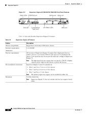
... slot RESET button Switch load 1000BASE-X GBIC display Uplink Ports Switch Load 100% 1% PORT 1 LINK PORT 2 LINK LINK LEDs 44312 Table 2-2 lists and describes Supervisor Engine 2 features Table 2-2 Supervisor Engine 2 Features Feature Chassis compatibility Software requirements (minimum) Fan tray requirements Slot installation restrictions Backplane Hardware restrictions Description Supported on all Catalyst 6500 series chassis...
... slot RESET button Switch load 1000BASE-X GBIC display Uplink Ports Switch Load 100% 1% PORT 1 LINK PORT 2 LINK LINK LEDs 44312 Table 2-2 lists and describes Supervisor Engine 2 features Table 2-2 Supervisor Engine 2 Features Feature Chassis compatibility Software requirements (minimum) Fan tray requirements Slot installation restrictions Backplane Hardware restrictions Description Supported on all Catalyst 6500 series chassis...

Supervisor Guide
Page 33
... redundant clock has failed. - Two VTT modules fail or the VTT module temperature major threshold has been exceeded3. - OL-7397-03 Catalyst 6500 Series Supervisor Engine Guide 2-5 The temperature of the supervisor engine major threshold has been exceeded. • Green-The port is active... environmental monitoring.) • Green-All chassis environmental monitors are reporting OK. • Orange-The power supply has failed or the power supply fan has failed. • Red-Incompatible power supplies are installed. - The supervisor engine is not connected. One VTT1 module has failed or the...
... redundant clock has failed. - Two VTT modules fail or the VTT module temperature major threshold has been exceeded3. - OL-7397-03 Catalyst 6500 Series Supervisor Engine Guide 2-5 The temperature of the supervisor engine major threshold has been exceeded. • Green-The port is active... environmental monitoring.) • Green-All chassis environmental monitors are reporting OK. • Orange-The power supply has failed or the power supply fan has failed. • Red-Incompatible power supplies are installed. - The supervisor engine is not connected. One VTT1 module has failed or the...
Supervisor Guide
Page 36
... 13-slot chassis Note The primary supervisor engine can be installed in the chassis. Catalyst 6500 Series Supervisor Engine Guide 2-8 OL-7397-03 Note The high-speed fan trays require that a high-speed fan tray (either slot. 32-Gbps shared bus. Table 2-6 Supervisor Engine 32 Features Feature... or higher capacity power supply in either a fan tray 2 or Catalyst 6500-E series fan tray) be installed in the chassis to power the fan tray. Note Supervisor Engine 32 does not include and does not support switch fabric. Low-speed fan trays do not provide sufficient cooling for Supervisor ...
... 13-slot chassis Note The primary supervisor engine can be installed in the chassis. Catalyst 6500 Series Supervisor Engine Guide 2-8 OL-7397-03 Note The high-speed fan trays require that a high-speed fan tray (either slot. 32-Gbps shared bus. Table 2-6 Supervisor Engine 32 Features Feature... or higher capacity power supply in either a fan tray 2 or Catalyst 6500-E series fan tray) be installed in the chassis to power the fan tray. Note Supervisor Engine 32 does not include and does not support switch fabric. Low-speed fan trays do not provide sufficient cooling for Supervisor ...

Supervisor Guide
Page 43
... capacity power supply in the chassis. Note The high-speed fan trays require that a high-speed fan tray (either a fan tray 2 or Catalyst 6500-E series fan tray) be installed in either slot. 32-Gbps shared bus. Low-speed fan trays do not provide sufficient cooling for Supervisor Engine 32 PISA.... Note Supervisor Engine 32 PISA does not include and does not support switch fabric....
... capacity power supply in the chassis. Note The high-speed fan trays require that a high-speed fan tray (either a fan tray 2 or Catalyst 6500-E series fan tray) be installed in either slot. 32-Gbps shared bus. Low-speed fan trays do not provide sufficient cooling for Supervisor Engine 32 PISA.... Note Supervisor Engine 32 PISA does not include and does not support switch fabric....

Supervisor Guide
Page 50
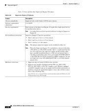
Table 2-14 Supervisor Engine 720 Features Feature Chassis compatibility Software requirements (minimum) Fan tray requirements Slot installation restrictions Backplane Hardware restrictions Memory Switch Processor DRAM Route Processor DRAM Switch Processor Bootflash/Bootdisk Route Processor Bootflash CompactFlash (disk0) Description Supported on all Catalyst 6500 series chassis. • Supervisor Engine 720-12.2(14)SX • Supervisor Engine...
Table 2-14 Supervisor Engine 720 Features Feature Chassis compatibility Software requirements (minimum) Fan tray requirements Slot installation restrictions Backplane Hardware restrictions Memory Switch Processor DRAM Route Processor DRAM Switch Processor Bootflash/Bootdisk Route Processor Bootflash CompactFlash (disk0) Description Supported on all Catalyst 6500 series chassis. • Supervisor Engine 720-12.2(14)SX • Supervisor Engine...
Supervisor Guide
Page 55
...engine can be installed in either a fan tray 2 or Catalyst 6500-E series fan tray) be installed in the chassis. All versions of Supervisor Engine 720-10GE require that a high-speed fan tray (either slot. 32-Gbps shared bus Integrated 720-Gbps Switch Fabric There are no additional hardware ...restrictions for Supervisor Engine 720-10GE. OL-7397-03 Catalyst 6500 Series Supervisor Engine Guide 2-27 Refer to your ...
...engine can be installed in either a fan tray 2 or Catalyst 6500-E series fan tray) be installed in the chassis. All versions of Supervisor Engine 720-10GE require that a high-speed fan tray (either slot. 32-Gbps shared bus Integrated 720-Gbps Switch Fabric There are no additional hardware ...restrictions for Supervisor Engine 720-10GE. OL-7397-03 Catalyst 6500 Series Supervisor Engine Guide 2-27 Refer to your ...
Supervisor Guide
Page 62
...Fan tray requirements Slot installation restrictions Description Supported only on hardware restrictions and module support, refer to the software release notes at the following URL: http://www.cisco.com/en/US/docs/switches/lan/catalyst6500/ios/12.2S Y/release/notes/ol_20679.html 2-34 Catalyst... chassis with either slot. Hardware restrictions Note When the Supervisor Engine 2T is a requirement that a high-speed fan tray be installed in Catalyst 6500 E-series switches. • Supports only modules equipped with DFC3 daughter cards are unused, have a module installed in the chassis....
...Fan tray requirements Slot installation restrictions Description Supported only on hardware restrictions and module support, refer to the software release notes at the following URL: http://www.cisco.com/en/US/docs/switches/lan/catalyst6500/ios/12.2S Y/release/notes/ol_20679.html 2-34 Catalyst... chassis with either slot. Hardware restrictions Note When the Supervisor Engine 2T is a requirement that a high-speed fan tray be installed in Catalyst 6500 E-series switches. • Supports only modules equipped with DFC3 daughter cards are unused, have a module installed in the chassis....

Supervisor Guide
Page 73
... engine in a Horizontal Slot Chassis Insert module between slot guides EMI gasket 3 4 4 55 66 1 2 3 4 FAN STATUS 5 6 130908 EMI gasket o o INPUT OK FAN OUTPUT OK FAIL INPUT OK FAN OUTPUT OK FAIL Ejector lever fully extended OL-7397-03 Catalyst 6500 Series Supervisor Engine Guide 3-5 Carefully slide the supervisor engine into the slot until the...
... engine in a Horizontal Slot Chassis Insert module between slot guides EMI gasket 3 4 4 55 66 1 2 3 4 FAN STATUS 5 6 130908 EMI gasket o o INPUT OK FAN OUTPUT OK FAIL INPUT OK FAN OUTPUT OK FAIL Ejector lever fully extended OL-7397-03 Catalyst 6500 Series Supervisor Engine Guide 3-5 Carefully slide the supervisor engine into the slot until the...

Supervisor Guide
Page 74
...gasket and the module or cover plate above it . (See Figure 3-2.) Note Do not press down too forcefully on the supervisor engine. Catalyst 6500 Series Supervisor Engine Guide 3-6 OL-7397-03 e. Note Make sure the ejector levers are flush with the supervisor engine faceplate. f.... that the supervisor engine STATUS LED is lit. Figure 3-2 Clearing the EMI Gasket in a Horizontal Slot Chassis 1 2 3 Press down 4 12 FAN STATUS 5 6 Press down , simultaneously close the left and right ejector levers to fully seat the supervisor engine in error messages. Installing a Supervisor Engine...
...gasket and the module or cover plate above it . (See Figure 3-2.) Note Do not press down too forcefully on the supervisor engine. Catalyst 6500 Series Supervisor Engine Guide 3-6 OL-7397-03 e. Note Make sure the ejector levers are flush with the supervisor engine faceplate. f.... that the supervisor engine STATUS LED is lit. Figure 3-2 Clearing the EMI Gasket in a Horizontal Slot Chassis 1 2 3 Press down 4 12 FAN STATUS 5 6 Press down , simultaneously close the left and right ejector levers to fully seat the supervisor engine in error messages. Installing a Supervisor Engine...

Supervisor Guide
Page 75
... WS-X6224 24 PORT 100FX STATUS ACTIVE SELECT NEXT o o INPUT OK FAN OUTPUT OK FAIL INPUT OK FAN OUTPUT OK FAIL Insert module between slot guides EMI gasket EMI gasket 6 4 3 130910 OL-7397-03 Catalyst 6500 Series Supervisor Engine Guide 3-7 b. Carefully slide the supervisor engine into the slot until the EMI gasket along...
... WS-X6224 24 PORT 100FX STATUS ACTIVE SELECT NEXT o o INPUT OK FAN OUTPUT OK FAIL INPUT OK FAN OUTPUT OK FAIL Insert module between slot guides EMI gasket EMI gasket 6 4 3 130910 OL-7397-03 Catalyst 6500 Series Supervisor Engine Guide 3-7 b. Carefully slide the supervisor engine into the slot until the EMI gasket along...

Supervisor Guide
Page 76
Tighten the two captive installation screws on the supervisor engine. Periodically check the STATUS LED: Catalyst 6500 Series Supervisor Engine Guide 3-8 OL-7397-03 Verify that the ejector levers are fully closed when they will bend and get damaged.... and exert a slight pressure to the left on the ejector levers, simultaneously close both levers to it 1mm FAN STATUS 48 Press left Press left 130911 o o INPUT OK FAN OUTPUT OK FAIL INPUT OK FAN OUTPUT OK FAIL c. e. f. While gently pressing to the left , deflecting the supervisor engine approximately 0.040 inches (1 ...
Tighten the two captive installation screws on the supervisor engine. Periodically check the STATUS LED: Catalyst 6500 Series Supervisor Engine Guide 3-8 OL-7397-03 Verify that the ejector levers are fully closed when they will bend and get damaged.... and exert a slight pressure to the left on the ejector levers, simultaneously close both levers to it 1mm FAN STATUS 48 Press left Press left 130911 o o INPUT OK FAN OUTPUT OK FAIL INPUT OK FAN OUTPUT OK FAIL c. e. f. While gently pressing to the left , deflecting the supervisor engine approximately 0.040 inches (1 ...

Supervisor Guide
Page 79
... 26 36 38 48 1 2 3 4 5 6 7 8 9 10 11 12 48 PORT 10/100 BASE-T 13 14 15 16 17 18 19 20 21 22 23 24 ETHERNET SWITCHING MODULE 25 26 27 28 29 30 31 32 33 34 35 36 37 38 39 40 41 42 43 44 45 46 47 48... o o INPUT OK FAN OUTPUT OK FAIL INPUT OK FAN OUTPUT OK FAIL 130906 Ejector lever Captive installation screw OL-7397-03 Catalyst 6500 Series Supervisor Engine Guide 3-11 Do not touch the module circuitry. b. Grasp the edges of...
... 26 36 38 48 1 2 3 4 5 6 7 8 9 10 11 12 48 PORT 10/100 BASE-T 13 14 15 16 17 18 19 20 21 22 23 24 ETHERNET SWITCHING MODULE 25 26 27 28 29 30 31 32 33 34 35 36 37 38 39 40 41 42 43 44 45 46 47 48... o o INPUT OK FAN OUTPUT OK FAIL INPUT OK FAN OUTPUT OK FAIL 130906 Ejector lever Captive installation screw OL-7397-03 Catalyst 6500 Series Supervisor Engine Guide 3-11 Do not touch the module circuitry. b. Grasp the edges of...

Supervisor Guide
Page 80
... 26 27 28 36 38 48 34 35 36 37 38 39 40 41 42 43 44 45 46 47 48 o o INPUT OK FAN OUTPUT OK FAIL INPUT OK FAN OUTPUT OK FAIL 130907 Step 6 Step 7 Place the removed module on an antistatic mat or in an antistatic bag, or immediately reinstall..., front covers, and rear covers are in another slot. Statement 1051 3-12 Catalyst 6500 Series Supervisor Engine Guide OL-7397-03 and they prevent exposure to either the supervisor engine or the module must have switching-module filler plates installed (Cisco part numbers WS-X6K-SLOT-CVR-E or SLOTBLANK-09). Warning Blank faceplates...
... 26 27 28 36 38 48 34 35 36 37 38 39 40 41 42 43 44 45 46 47 48 o o INPUT OK FAN OUTPUT OK FAIL INPUT OK FAN OUTPUT OK FAIL 130907 Step 6 Step 7 Place the removed module on an antistatic mat or in an antistatic bag, or immediately reinstall..., front covers, and rear covers are in another slot. Statement 1051 3-12 Catalyst 6500 Series Supervisor Engine Guide OL-7397-03 and they prevent exposure to either the supervisor engine or the module must have switching-module filler plates installed (Cisco part numbers WS-X6K-SLOT-CVR-E or SLOTBLANK-09). Warning Blank faceplates...
Supervisor Guide
Page 109
Index fan tray requirements 2-8 front panel (figure) 2-7, 2-8 hardware restrictions 2-9 memory 2-10 model descriptions (table) 2-7 MSFC support 2-11 operating altitude 2-12 operating temperature 2-12 PFC support 2-11 physical and environmental specifications (table) 2-12 power requirement 2-12 reset switch 2-10 slot restrictions 2-8 transceivers supported 2-11 types 2-7 uplink port queue structure 2-11...2-23 versions (table) 2-21 Supervisor Engine 720-10GE console port 2-28 description 2-26 features (table) 2-27, 2-34 front panel (figure) 2-26 Catalyst 6500 Series Supervisor Engine Guide IN-3
Index fan tray requirements 2-8 front panel (figure) 2-7, 2-8 hardware restrictions 2-9 memory 2-10 model descriptions (table) 2-7 MSFC support 2-11 operating altitude 2-12 operating temperature 2-12 PFC support 2-11 physical and environmental specifications (table) 2-12 power requirement 2-12 reset switch 2-10 slot restrictions 2-8 transceivers supported 2-11 types 2-7 uplink port queue structure 2-11...2-23 versions (table) 2-21 Supervisor Engine 720-10GE console port 2-28 description 2-26 features (table) 2-27, 2-34 front panel (figure) 2-26 Catalyst 6500 Series Supervisor Engine Guide IN-3