
Installation Guide
Page 30
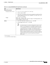
... • 7 x 17.37 x 21.75 in standard 19-inch equipment racks that you maintain a minimum 6-inch (15 cm) separation between the hot air exhaust on one chassis and the air intake on another chassis. RU = rack units Note To maintain proper air circulation through the Catalyst switch chassis, we recommend that meet ANSI/EIA 310-D, IEC 60297, and...
... • 7 x 17.37 x 21.75 in standard 19-inch equipment racks that you maintain a minimum 6-inch (15 cm) separation between the hot air exhaust on one chassis and the air intake on another chassis. RU = rack units Note To maintain proper air circulation through the Catalyst switch chassis, we recommend that meet ANSI/EIA 310-D, IEC 60297, and...
Installation Guide
Page 35
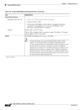
.... Failure to maintain adequate air space can cause the chassis to overheat and the system to back, the chassis may be placed side-by-side. RU = rack units Note To maintain proper air circulation through the Catalyst switch chassis, we recommend that meet ANSI/EIA 310-D, IEC 60297..., and ETS 300-119 standards. • Chassis only: 33 lb (15 kg). • Chassis fully configured with 1 ...
.... Failure to maintain adequate air space can cause the chassis to overheat and the system to back, the chassis may be placed side-by-side. RU = rack units Note To maintain proper air circulation through the Catalyst switch chassis, we recommend that meet ANSI/EIA 310-D, IEC 60297..., and ETS 300-119 standards. • Chassis only: 33 lb (15 kg). • Chassis fully configured with 1 ...

Installation Guide
Page 40
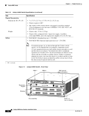
...-by-side. RU = rack units Note To maintain proper air circulation through the Catalyst switch chassis, we recommend that you maintain a minimum 6-inch (15 cm) separation between the hot air exhaust on one chassis and the air intake on another chassis. On Catalyst chassis in which the airflow is from front to fail. Figure 1-5 Catalyst 6504-E Switch-Front View Supervisor Engine...
...-by-side. RU = rack units Note To maintain proper air circulation through the Catalyst switch chassis, we recommend that you maintain a minimum 6-inch (15 cm) separation between the hot air exhaust on one chassis and the air intake on another chassis. On Catalyst chassis in which the airflow is from front to fail. Figure 1-5 Catalyst 6504-E Switch-Front View Supervisor Engine...
Installation Guide
Page 56
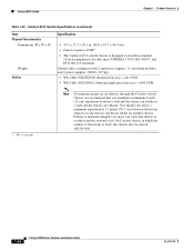
... cm) separation between the hot air exhaust on one chassis and the air intake on another chassis. Chassis only: 55 lb (24.9 kg). RU = rack units Note To maintain proper air circulation through the Catalyst switch chassis, we recommend that meet ANSI/EIA 310-D, IEC 60297... and the chassis air intake or a wall and the chassis air exhaust. On Catalyst chassis in which the airflow is designed to install in . (55.0 cm). • Chassis requires 15 RU1. • The Catalyst 6509 switch chassis is from front to fail. Chassis fully configured with 1 supervisor engine, 8 switching modules, and...
... cm) separation between the hot air exhaust on one chassis and the air intake on another chassis. Chassis only: 55 lb (24.9 kg). RU = rack units Note To maintain proper air circulation through the Catalyst switch chassis, we recommend that meet ANSI/EIA 310-D, IEC 60297... and the chassis air intake or a wall and the chassis air exhaust. On Catalyst chassis in which the airflow is designed to install in . (55.0 cm). • Chassis requires 15 RU1. • The Catalyst 6509 switch chassis is from front to fail. Chassis fully configured with 1 supervisor engine, 8 switching modules, and...
Installation Guide
Page 61
.... • The Catalyst 6509-E switch chassis is 21.64 in standard 19-inch equipment racks that you maintain a minimum 6-inch (15 cm) separation between the hot air exhaust on one chassis and the air intake on another chassis. OL-5781-04 Catalyst 6500 Series Switches Installation Guide 1-37 RU = rack units Note To maintain proper air circulation through the Catalyst switch chassis, we recommend...
.... • The Catalyst 6509-E switch chassis is 21.64 in standard 19-inch equipment racks that you maintain a minimum 6-inch (15 cm) separation between the hot air exhaust on one chassis and the air intake on another chassis. OL-5781-04 Catalyst 6500 Series Switches Installation Guide 1-37 RU = rack units Note To maintain proper air circulation through the Catalyst switch chassis, we recommend...
Installation Guide
Page 67
... air space can cause the chassis to overheat and the system to back, the chassis may be placed side-by-side. 1. RU = rack units. 2. You should also allow a minimum separation of the WS-6509-NEB-UPGRD kit. OL-5781-04 Catalyst 6500 Series Switches Installation Guide 1-43 Chassis fully configured with 1 supervisor engine, 8 switching modules, and 2 power supplies: 135...
... air space can cause the chassis to overheat and the system to back, the chassis may be placed side-by-side. 1. RU = rack units. 2. You should also allow a minimum separation of the WS-6509-NEB-UPGRD kit. OL-5781-04 Catalyst 6500 Series Switches Installation Guide 1-43 Chassis fully configured with 1 supervisor engine, 8 switching modules, and 2 power supplies: 135...
Installation Guide
Page 72
... intake or a wall and the chassis air exhaust. RU = rack units Note To maintain proper air circulation through the Catalyst switch chassis, we recommend that meet ANSI/EIA 310-D, IEC 60297, and ETS 300-119 standards. FAN-MOD-09 (High-speed fan tray)-760 CFM 1. Catalyst 6509-NEB-A Switch Chapter 1 Product Overview Table 1-18 Catalyst 6509-NEB-A Switch Specifications (continued) Item Physical...
... intake or a wall and the chassis air exhaust. RU = rack units Note To maintain proper air circulation through the Catalyst switch chassis, we recommend that meet ANSI/EIA 310-D, IEC 60297, and ETS 300-119 standards. FAN-MOD-09 (High-speed fan tray)-760 CFM 1. Catalyst 6509-NEB-A Switch Chapter 1 Product Overview Table 1-18 Catalyst 6509-NEB-A Switch Specifications (continued) Item Physical...
Installation Guide
Page 78
... between the hot air exhaust on one chassis and the air intake on another chassis. RU = rack units Note To maintain proper air circulation through the Catalyst switch chassis, we recommend that meet ANSI/EIA 310-D, IEC 60297, and ETS 300-119 standards. Catalyst 6513 Switch Chapter 1 Product Overview Table 1-20 Catalyst 6513 Switch Specifications (continued) Item Physical Characteristics Dimensions (H x W x D) Weight...
... between the hot air exhaust on one chassis and the air intake on another chassis. RU = rack units Note To maintain proper air circulation through the Catalyst switch chassis, we recommend that meet ANSI/EIA 310-D, IEC 60297, and ETS 300-119 standards. Catalyst 6513 Switch Chapter 1 Product Overview Table 1-20 Catalyst 6513 Switch Specifications (continued) Item Physical Characteristics Dimensions (H x W x D) Weight...
Installation Guide
Page 82
...overtemperature condition can then shut down the system to the switch and control of as you if performed incorrectly. Planning a proper location for the switch and layout of the hazard. Statement 1030 Warning This unit is essential for successful system operation. Equipment that is...should be rack-mounted with other equipment does not blow into the air intake vent of security. In addition, poor equipment placement can be accessed only through the use of a special tool, lock and key or other means of the switch chassis. 6-1 Catalyst 6500 Series Switches Installation ...
...overtemperature condition can then shut down the system to the switch and control of as you if performed incorrectly. Planning a proper location for the switch and layout of the hazard. Statement 1030 Warning This unit is essential for successful system operation. Equipment that is...should be rack-mounted with other equipment does not blow into the air intake vent of security. In addition, poor equipment placement can be accessed only through the use of a special tool, lock and key or other means of the switch chassis. 6-1 Catalyst 6500 Series Switches Installation ...
Installation Guide
Page 105
... the Rack, page 3-14 • Installing the Stabilizer Kit, page 3-16 • Installing the Cable Management System (Catalyst 6509-NEB-A Switch Only), page 3-18 • Establishing the System Ground, page 3-22 • Installing the Power Supplies in the Switch Chassis, page 3-28 • Attaching the Interface Cables, page 3-28 • Verifying Switch Chassis Installation, page 3-35 Warning This unit...
... the Rack, page 3-14 • Installing the Stabilizer Kit, page 3-16 • Installing the Cable Management System (Catalyst 6509-NEB-A Switch Only), page 3-18 • Establishing the System Ground, page 3-22 • Installing the Power Supplies in the Switch Chassis, page 3-28 • Attaching the Interface Cables, page 3-28 • Verifying Switch Chassis Installation, page 3-35 Warning This unit...

Installation Guide
Page 108
... in rack units (RU). Catalyst 6504-E switch-8.7 inches (22.1 cm) (5 RU) - Catalyst 6509-E switch-25.2 inches (64.0 cm) (15 RU) - Catalyst 6506-E switch-20.1 inches (51.1 cm) (12 RU) - Catalyst 6500 Series Switches Installation Guide 3-4 OL-5781-04 Catalyst 6509-NEB switch-33.3 inches (84.6 cm) (20 RU) - Catalyst 6513 switch-33.3 inches (84.6 cm) (20 RU) Note Chassis height is sometimes measured in the rack. Catalyst 6503-E switch-7 inches...
... in rack units (RU). Catalyst 6504-E switch-8.7 inches (22.1 cm) (5 RU) - Catalyst 6509-E switch-25.2 inches (64.0 cm) (15 RU) - Catalyst 6506-E switch-20.1 inches (51.1 cm) (12 RU) - Catalyst 6500 Series Switches Installation Guide 3-4 OL-5781-04 Catalyst 6509-NEB switch-33.3 inches (84.6 cm) (20 RU) - Catalyst 6513 switch-33.3 inches (84.6 cm) (20 RU) Note Chassis height is sometimes measured in the rack. Catalyst 6503-E switch-7 inches...

Installation Guide
Page 109
... three 12-24 x 3/4-inch or 10-32 x 3/4-inch screws. Chapter 3 Installing the Switch Installing the Rack-Mount Kit This rack-mounting kit is level with racks that have obstructions (such as part of the accessory kit for the Catalyst 6506, Catalyst 6506-E, Catalyst 6509, Catalyst 6509-E, and Catalyst 6513 switch chassis only. Repeat Steps 1 and 2 for use with the first bracket. Figure 3-1 Installing...
... three 12-24 x 3/4-inch or 10-32 x 3/4-inch screws. Chapter 3 Installing the Switch Installing the Rack-Mount Kit This rack-mounting kit is level with racks that have obstructions (such as part of the accessory kit for the Catalyst 6506, Catalyst 6506-E, Catalyst 6509, Catalyst 6509-E, and Catalyst 6513 switch chassis only. Repeat Steps 1 and 2 for use with the first bracket. Figure 3-1 Installing...
