
Installation Guide
Page 7
...4 C H A P T E R Installing the Cable Management System (Catalyst 6509-NEB-A Switch Only) 3-23 Replacing the Cable Guide 3-25 Establishing the System Ground 3-27 Required Tools and Parts 3-28 Connecting the System Ground 3-29 Installing the Power Supplies in the Switch Chassis 3-34 Attaching the Interface Cables 3-34 Connecting the Supervisor Engine Console Port ... the Fan Assembly 4-57 Installing the Fan Assembly 4-65 Checking the Installation 4-65 Installing the Air Filter Assembly on a Catalyst 6509-NEB-A Switch (Optional) 4-66 OL-5781-04 Catalyst 6500 Series Switches Installation Guide vii
...4 C H A P T E R Installing the Cable Management System (Catalyst 6509-NEB-A Switch Only) 3-23 Replacing the Cable Guide 3-25 Establishing the System Ground 3-27 Required Tools and Parts 3-28 Connecting the System Ground 3-29 Installing the Power Supplies in the Switch Chassis 3-34 Attaching the Interface Cables 3-34 Connecting the Supervisor Engine Console Port ... the Fan Assembly 4-57 Installing the Fan Assembly 4-65 Checking the Installation 4-65 Installing the Air Filter Assembly on a Catalyst 6509-NEB-A Switch (Optional) 4-66 OL-5781-04 Catalyst 6500 Series Switches Installation Guide vii
Installation Guide
Page 8
...-Input Power Supplies A-38 4000 W Power Supply Specifications A-39 4000 W Power Supply AC Power Cords A-42 6000 W AC-Input Power Supply A-43 6000 W Power Supply Specifications A-44 6000 W Power Supply AC Power Cords A-46 AC Power Cord Illustrations A-47 Power Supply Redundancy A-57 B A P P E N D I X Transceivers, Module Connectors, and Cable Specifications B-1 Transceivers B-1 100-MB Transceiver Modules B-2 1-GB Transceiver Modules B-3 10-GB Transceiver Modules B-8 WDM Transceiver Modules B-10 Catalyst 6500 Series Switches Installation...
...-Input Power Supplies A-38 4000 W Power Supply Specifications A-39 4000 W Power Supply AC Power Cords A-42 6000 W AC-Input Power Supply A-43 6000 W Power Supply Specifications A-44 6000 W Power Supply AC Power Cords A-46 AC Power Cord Illustrations A-47 Power Supply Redundancy A-57 B A P P E N D I X Transceivers, Module Connectors, and Cable Specifications B-1 Transceivers B-1 100-MB Transceiver Modules B-2 1-GB Transceiver Modules B-3 10-GB Transceiver Modules B-8 WDM Transceiver Modules B-10 Catalyst 6500 Series Switches Installation...

Installation Guide
Page 9
... Cord B-29 Cleaning the Fiber Optic Connectors B-31 Repacking the Switch C-1 Chassis and Module Power and Heat Values D-1 Troubleshooting E-1 Getting Started E-1 Solving Problems at the System Component Level E-2 Identifying Startup Problems E-3 Troubleshooting the Power Supply E-4 Troubleshooting the Fan Assembly E-5 Troubleshooting Modules E-5 STATUS LED Indications E-5 Contacting Customer Service E-7 Contents OL-5781-04 Catalyst 6500 Series Switches Installation Guide ix
... Cord B-29 Cleaning the Fiber Optic Connectors B-31 Repacking the Switch C-1 Chassis and Module Power and Heat Values D-1 Troubleshooting E-1 Getting Started E-1 Solving Problems at the System Component Level E-2 Identifying Startup Problems E-3 Troubleshooting the Power Supply E-4 Troubleshooting the Fan Assembly E-5 Troubleshooting Modules E-5 STATUS LED Indications E-5 Contacting Customer Service E-7 Contents OL-5781-04 Catalyst 6500 Series Switches Installation Guide ix
Installation Guide
Page 11
... install your site before installing the Catalyst 6500 series switch. Preparing for the Catalyst 6500 series switch AC-input and DC-input power supplies and the AC power cords. Installing the Switch Describes how to consider when preparing your Catalyst 6500 series switch. OL-5781-04 Catalyst 6500 Series Switches Installation Guide xi Removal and Provides procedures for removing and installing chassis Replacement Procedures components. Audience Only...
... install your site before installing the Catalyst 6500 series switch. Preparing for the Catalyst 6500 series switch AC-input and DC-input power supplies and the AC power cords. Installing the Switch Describes how to consider when preparing your Catalyst 6500 series switch. OL-5781-04 Catalyst 6500 Series Switches Installation Guide xi Removal and Provides procedures for removing and installing chassis Replacement Procedures components. Audience Only...
Installation Guide
Page 28
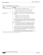
... power supplies). - Note For Catalyst 6503 and Catalyst 6503-E chassis that are equipped with DC-input power supplies, the system (NEBS) ground serves as the primary safety ground and must be of phase between multiple power supplies or multiple AC-power plugs on the same power supply because all AC power supply inputs are isolated. • Single power supplies are installed in the lower power supply bay. Catalyst 6500 Series Switches...
... power supplies). - Note For Catalyst 6503 and Catalyst 6503-E chassis that are equipped with DC-input power supplies, the system (NEBS) ground serves as the primary safety ground and must be of phase between multiple power supplies or multiple AC-power plugs on the same power supply because all AC power supply inputs are isolated. • Single power supplies are installed in the lower power supply bay. Catalyst 6500 Series Switches...
Installation Guide
Page 30
... Note To maintain proper air circulation through the Catalyst switch chassis, we recommend that meet ANSI/EIA 310-D, IEC 60297, and ETS 300-119 standards. • Chassis only: 27 lb (12.25 kg). • Chassis fully configured with 1 supervisor engine, 2 modules, 2 AC-input PEMs, and 2 AC-input power supplies: 85.4 lb (38.7 kg). • FAN-MOD-3...LINK LINK LINK 13 14 15 16 LINK LINK LINK LINK Slots 1-3 (top to fail. Failure to maintain adequate air space can cause the chassis to overheat and the system to bottom) Catalyst 6500 Series Switches Installation Guide 1-6 OL-5781-04
... Note To maintain proper air circulation through the Catalyst switch chassis, we recommend that meet ANSI/EIA 310-D, IEC 60297, and ETS 300-119 standards. • Chassis only: 27 lb (12.25 kg). • Chassis fully configured with 1 supervisor engine, 2 modules, 2 AC-input PEMs, and 2 AC-input power supplies: 85.4 lb (38.7 kg). • FAN-MOD-3...LINK LINK LINK 13 14 15 16 LINK LINK LINK LINK Slots 1-3 (top to fail. Failure to maintain adequate air space can cause the chassis to overheat and the system to bottom) Catalyst 6500 Series Switches Installation Guide 1-6 OL-5781-04
Installation Guide
Page 31
Chapter 1 Product Overview Figure 1-2 Catalyst 6503 Switch-Rear View Power supply 2 (redundant) Power supply 1 INPUT FAN OUTPUT OK OK FAIL INPUT OK FAN OUTPUT OK FAIL Catalyst 6503 Switch 63031 OL-5781-04 Catalyst 6500 Series Switches Installation Guide 1-7
Chapter 1 Product Overview Figure 1-2 Catalyst 6503 Switch-Rear View Power supply 2 (redundant) Power supply 1 INPUT FAN OUTPUT OK OK FAIL INPUT OK FAN OUTPUT OK FAIL Catalyst 6503 Switch 63031 OL-5781-04 Catalyst 6500 Series Switches Installation Guide 1-7
Installation Guide
Page 33
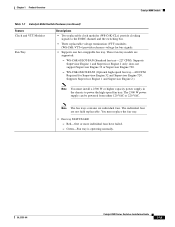
... W DC-input power supply). - OL-5781-04 Catalyst 6500 Series Switches Installation Guide 1-9 Red-One or more individual fans have failed. PWR-950-AC (950 W AC-input power supply). - The following power supplies are supported: - PEM-DC/3 (PEM for 950 W AC-input power supplies). - Source AC can be out of different wattage ratings. Chapter 1 Product Overview Catalyst 6503-E Switch Table 1-3 Catalyst 6503-E Switch Features (continued...
... W DC-input power supply). - OL-5781-04 Catalyst 6500 Series Switches Installation Guide 1-9 Red-One or more individual fans have failed. PWR-950-AC (950 W AC-input power supply). - The following power supplies are supported: - PEM-DC/3 (PEM for 950 W AC-input power supplies). - Source AC can be out of different wattage ratings. Chapter 1 Product Overview Catalyst 6503-E Switch Table 1-3 Catalyst 6503-E Switch Features (continued...
Installation Guide
Page 35
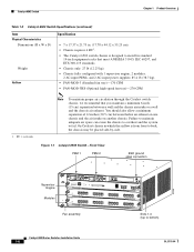
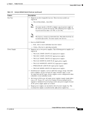
... Catalyst 6500 Series Switches Installation Guide 1-11 On Catalyst chassis in which the airflow is designed to install in . (17.78 x 44.12 x 55.25 cm). • Chassis requires 4 RU1. • The Catalyst 6503-E switch chassis is from front to back, the chassis ...standards. • Chassis only: 33 lb (15 kg). • Chassis fully configured with 1 supervisor engine, 2 modules, 2 AC-input PEMs, and 2 AC-input power supplies: 85.4 lb (38.7 kg). • WS-C6503-E-FAN-282 CFM 1. Chapter 1 Product Overview Catalyst 6503-E Switch Table 1-4 Catalyst 6503-E Switch Specifications (continued)...
... Catalyst 6500 Series Switches Installation Guide 1-11 On Catalyst chassis in which the airflow is designed to install in . (17.78 x 44.12 x 55.25 cm). • Chassis requires 4 RU1. • The Catalyst 6503-E switch chassis is from front to back, the chassis ...standards. • Chassis only: 33 lb (15 kg). • Chassis fully configured with 1 supervisor engine, 2 modules, 2 AC-input PEMs, and 2 AC-input power supplies: 85.4 lb (38.7 kg). • WS-C6503-E-FAN-282 CFM 1. Chapter 1 Product Overview Catalyst 6503-E Switch Table 1-4 Catalyst 6503-E Switch Specifications (continued)...
Installation Guide
Page 36
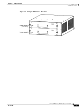
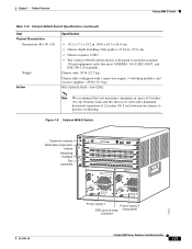
Catalyst 6503-E Switch Figure 1-3 Catalyst 6503-E Switch-Front View PEM 1 PEM 2 Chapter 1 Product Overview ESD ground strap connection 91239 Supervisor Engine Modules WS-X6K-SUP2-2GE STATUS SYSTEMCONSOLPEWR MGRMETSET SUPERVISOR2 CONSOLE ...PORT 1 LINK PORT 2 LINK 13 14 15 16 LINK LINK LINK LINK 13 14 15 16 LINK LINK LINK LINK Slots 1-3 (top to bottom) Figure 1-4 Catalyst 6503-E Switch-Rear View 63031 Power supply 2 (redundant) Power supply 1 INPUT OK FAN OUTPUT OK FAIL INPUT FAN OUTPUT OK OK FAIL 1-12 Catalyst 6500 Series Switches Installation Guide OL-5781-04
Catalyst 6503-E Switch Figure 1-3 Catalyst 6503-E Switch-Front View PEM 1 PEM 2 Chapter 1 Product Overview ESD ground strap connection 91239 Supervisor Engine Modules WS-X6K-SUP2-2GE STATUS SYSTEMCONSOLPEWR MGRMETSET SUPERVISOR2 CONSOLE ...PORT 1 LINK PORT 2 LINK 13 14 15 16 LINK LINK LINK LINK 13 14 15 16 LINK LINK LINK LINK Slots 1-3 (top to bottom) Figure 1-4 Catalyst 6503-E Switch-Rear View 63031 Power supply 2 (redundant) Power supply 1 INPUT OK FAN OUTPUT OK FAIL INPUT FAN OUTPUT OK OK FAIL 1-12 Catalyst 6500 Series Switches Installation Guide OL-5781-04
Installation Guide
Page 38
...°F (0° to hot) 1-14 Catalyst 6500 Series Switches Installation Guide OL-5781-04 The following power supplies are triggered at 40°C (104°...Catalyst 6500 series switches are equipped with internal air temperature sensors that are supported: - The individual fans are supported: - The second power supply is operating normally. • Supports one hot-swappable fan tray. Power supplies can be out of phase between multiple power supplies or multiple AC-power plugs on the same power supply because all AC power supply inputs are isolated. • Single power supplies...
...°F (0° to hot) 1-14 Catalyst 6500 Series Switches Installation Guide OL-5781-04 The following power supplies are triggered at 40°C (104°...Catalyst 6500 series switches are equipped with internal air temperature sensors that are supported: - The individual fans are supported: - The second power supply is operating normally. • Supports one hot-swappable fan tray. Power supplies can be out of phase between multiple power supplies or multiple AC-power plugs on the same power supply because all AC power supply inputs are isolated. • Single power supplies...
Installation Guide
Page 39
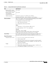
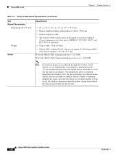
...; The Catalyst 6504-E switch chassis is designed to 76 dB. Chapter 1 Product Overview Catalyst 6504-E Switch Table 1-6 Catalyst 6504-E Switch Specifications (continued) Item Humidity (RH), ambient (noncondensing) operating Humidity (RH), ambient (noncondensing) nonoperating and storage Altitude, operating Shock and vibration Acoustic Noise Physical Characteristics Dimensions (H x W x D) Weight Specification 5% to 90% 5% to 95% Certified for operation: 0 to 6500 feet (0 to...
...; The Catalyst 6504-E switch chassis is designed to 76 dB. Chapter 1 Product Overview Catalyst 6504-E Switch Table 1-6 Catalyst 6504-E Switch Specifications (continued) Item Humidity (RH), ambient (noncondensing) operating Humidity (RH), ambient (noncondensing) nonoperating and storage Altitude, operating Shock and vibration Acoustic Noise Physical Characteristics Dimensions (H x W x D) Weight Specification 5% to 90% 5% to 95% Certified for operation: 0 to 6500 feet (0 to...
Installation Guide
Page 42
... 5 or slot 6. • Some Catalyst 6500 series modules may: - Not be powered from 1 (top) to five Catalyst 6500 series modules. • WS-C6500-SFM and WS-X6500-SFM2 Switch Fabric Modules must also install a 2500 W or higher capacity power supply in switching fabric. Require that you install a Supervisor Engine 720 - Table 1-7 Catalyst 6506 Switch Features Feature Chassis Supervisor Engines Descriptions • Six...
... 5 or slot 6. • Some Catalyst 6500 series modules may: - Not be powered from 1 (top) to five Catalyst 6500 series modules. • WS-C6500-SFM and WS-X6500-SFM2 Switch Fabric Modules must also install a 2500 W or higher capacity power supply in switching fabric. Require that you install a Supervisor Engine 720 - Table 1-7 Catalyst 6506 Switch Features Feature Chassis Supervisor Engines Descriptions • Six...
Installation Guide
Page 43
...-FAN (Standard fan tray-227 CFM). Supports Supervisor Engine 1 and Supervisor Engine 2 only; OL-5781-04 Catalyst 6500 Series Switches Installation Guide 1-19 You must install a 2500 W or higher capacity power supply in the chassis to the EOBC channel and the switching bus. • Three replaceable voltage termination (VTT) modules (WS-C6K-VTT=) provide reference voltage for...
...-FAN (Standard fan tray-227 CFM). Supports Supervisor Engine 1 and Supervisor Engine 2 only; OL-5781-04 Catalyst 6500 Series Switches Installation Guide 1-19 You must install a 2500 W or higher capacity power supply in the chassis to the EOBC channel and the switching bus. • Three replaceable voltage termination (VTT) modules (WS-C6K-VTT=) provide reference voltage for...
Installation Guide
Page 44
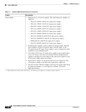
... high-speed fan tray. 1. When installed in a Catalyst 6506 switch chassis, the 6000 W power supply has a maximum output of phase between multiple power supplies or multiple AC-power plugs on the same power supply because all AC power supply inputs are isolated. • Single power supplies are supported: - WS-CAC-6000W (6000 W AC-input power supply)1. • Installed power supplies can be of different wattage ratings. The second...
... high-speed fan tray. 1. When installed in a Catalyst 6506 switch chassis, the 6000 W power supply has a maximum output of phase between multiple power supplies or multiple AC-power plugs on the same power supply because all AC power supply inputs are isolated. • Single power supplies are supported: - WS-CAC-6000W (6000 W AC-input power supply)1. • Installed power supplies can be of different wattage ratings. The second...
Installation Guide
Page 46
...Catalyst chassis in which the airflow is designed to install in . (55.0 cm). • Chassis requires 12 RU. • The Catalyst 6506 switch chassis is from front to fail. Failure to maintain adequate air space can cause the chassis to overheat and the system to back, the chassis may be placed side-by-side. 1-22 Catalyst 6500 Series Switches...the Catalyst switch chassis, we recommend that meet ANSI/EIA 310-D, IEC 60297, and ETS 300-119 standards. • Chassis only: 45 lb (20.4 kg). • Chassis fully configured with 1 supervisor engine, 5 switching modules, and 2 power supplies: ...
...Catalyst chassis in which the airflow is designed to install in . (55.0 cm). • Chassis requires 12 RU. • The Catalyst 6506 switch chassis is from front to fail. Failure to maintain adequate air space can cause the chassis to overheat and the system to back, the chassis may be placed side-by-side. 1-22 Catalyst 6500 Series Switches...the Catalyst switch chassis, we recommend that meet ANSI/EIA 310-D, IEC 60297, and ETS 300-119 standards. • Chassis only: 45 lb (20.4 kg). • Chassis fully configured with 1 supervisor engine, 5 switching modules, and 2 power supplies: ...
Installation Guide
Page 47
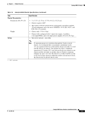
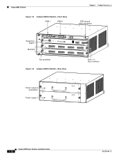
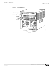
Chapter 1 Product Overview Figure 1-7 Catalyst 6506 Switch Supervisor engine Redundant supervisor engine Switching modules Fan assembly 1 2 3 4 FAN STATUS 5 6 WS-X6K-SUP2-2GE STATUS SYSTEMCONSOLPEWR MGRMETSET SUPERVISOR2 CONSOLE WS-X6K-SUP2-2GE STATUS SYSTEMCONSOLPEWR MGRMETSET SUPERVISOR2 CONSOLE ... LINK LINK LINK LINK LINK LINK LINK LINK LINK LINK LINK o o INPUT OK FAN OUTPUT OK FAIL INPUT OK FAN OUTPUT OK FAIL Power supply 1 Power supply 2 ESD ground strap (redundant) connector Catalyst 6506 Switch 18224 OL-5781-04 Catalyst 6500 Series Switches Installation Guide 1-23
Chapter 1 Product Overview Figure 1-7 Catalyst 6506 Switch Supervisor engine Redundant supervisor engine Switching modules Fan assembly 1 2 3 4 FAN STATUS 5 6 WS-X6K-SUP2-2GE STATUS SYSTEMCONSOLPEWR MGRMETSET SUPERVISOR2 CONSOLE WS-X6K-SUP2-2GE STATUS SYSTEMCONSOLPEWR MGRMETSET SUPERVISOR2 CONSOLE ... LINK LINK LINK LINK LINK LINK LINK LINK LINK LINK LINK o o INPUT OK FAN OUTPUT OK FAIL INPUT OK FAN OUTPUT OK FAIL Power supply 1 Power supply 2 ESD ground strap (redundant) connector Catalyst 6506 Switch 18224 OL-5781-04 Catalyst 6500 Series Switches Installation Guide 1-23
Installation Guide
Page 49
...-DC (4000 W DC-input power supply). - Power supplies can be out of different wattage ratings. The following power supplies are supported: - Installed power supplies can be configured in the left power supply bay. OL-5781-04 Catalyst 6500 Series Switches Installation Guide 1-25 Power Supply Note The fan tray contains six individual fans. Green-Fan tray is installed in the chassis to power the fan tray. WS...
...-DC (4000 W DC-input power supply). - Power supplies can be out of different wattage ratings. The following power supplies are supported: - Installed power supplies can be configured in the left power supply bay. OL-5781-04 Catalyst 6500 Series Switches Installation Guide 1-25 Power Supply Note The fan tray contains six individual fans. Green-Fan tray is installed in the chassis to power the fan tray. WS...
Installation Guide
Page 51
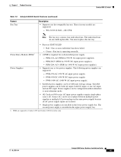
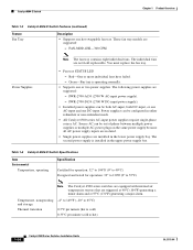
... FAIL INPUT OK FAN OUTPUT OK FAIL Power supply 1 Power supply 2 ESD ground strap (redundant) connector 113673 Catalyst 6500 Series Switches Installation Guide 1-27 Chapter 1 Product Overview Catalyst 6506-E Switch Table 1-10 Catalyst 6506-E Switch Specifications (continued) Item Physical Characteristics Dimensions (H x W x D) Weight Airflow Specification • 19.2 x 17.5 x 18.2 in. (48.8 x 44.5 x 46.0 cm). • Chassis depth including cable guide is 21.64...
... FAIL INPUT OK FAN OUTPUT OK FAIL Power supply 1 Power supply 2 ESD ground strap (redundant) connector 113673 Catalyst 6500 Series Switches Installation Guide 1-27 Chapter 1 Product Overview Catalyst 6506-E Switch Table 1-10 Catalyst 6506-E Switch Specifications (continued) Item Physical Characteristics Dimensions (H x W x D) Weight Airflow Specification • 19.2 x 17.5 x 18.2 in. (48.8 x 44.5 x 46.0 cm). • Chassis depth including cable guide is 21.64...
Installation Guide
Page 52
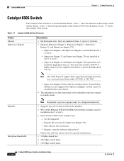
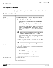
.... • 32 GBps shared bus. • 256 GBps switch fabric. • 720 GBps switch fabric. 1-28 Catalyst 6500 Series Switches Installation Guide OL-5781-04 Catalyst 6509 Switch Chapter 1 Product Overview Catalyst 6509 Switch The Catalyst 6509 switch is a 9-slot horizontal chassis. Supervisor Engine 32 and Supervisor Engine 720 are installed in standby mode. Note The 2500 W power supply, when supporting the high-speed fan tray, can...
.... • 32 GBps shared bus. • 256 GBps switch fabric. • 720 GBps switch fabric. 1-28 Catalyst 6500 Series Switches Installation Guide OL-5781-04 Catalyst 6509 Switch Chapter 1 Product Overview Catalyst 6509 Switch The Catalyst 6509 switch is a 9-slot horizontal chassis. Supervisor Engine 32 and Supervisor Engine 720 are installed in standby mode. Note The 2500 W power supply, when supporting the high-speed fan tray, can...

