
Hardware Installation Guide
Page 9
... Terminal to the Console Port 3-8 Powering On the Switch and Running POST 3-10 Powering Off the Switch and Disconnecting the Console Port 3-11 Planning the Stack 3-12 Planning Considerations 3-12 Powering Considerations 3-13 Cabling Considerations 3-14 Recommended Cabling Configurations 3-15 Installing the Switch 3-17 Rack Mounting 3-18 Removing Screws from the Switch 3-19 Attaching Brackets to the Catalyst 3750G-24TS Switch 3-20 Attaching Brackets to the Catalyst 3750-24TS, 3750G-24T, 3750G-12S, and 3750-48TS Switches...
... Terminal to the Console Port 3-8 Powering On the Switch and Running POST 3-10 Powering Off the Switch and Disconnecting the Console Port 3-11 Planning the Stack 3-12 Planning Considerations 3-12 Powering Considerations 3-13 Cabling Considerations 3-14 Recommended Cabling Configurations 3-15 Installing the Switch 3-17 Rack Mounting 3-18 Removing Screws from the Switch 3-19 Attaching Brackets to the Catalyst 3750G-24TS Switch 3-20 Attaching Brackets to the Catalyst 3750-24TS, 3750G-24T, 3750G-12S, and 3750-48TS Switches...

Hardware Installation Guide
Page 11
...-In Notes C-8 Where to Go Next C-8 Quick Setup By Using the CLI-Based Setup Program D-1 Methods for Accessing the CLI D-2 Accessing the CLI Through Express Setup (Unconfigured Switch Only) D-2 Accessing the CLI Through the Console Port D-3 Taking Out What You Need D-4 Stacking the Switches (Optional) D-5 Connecting to the Console Port D-7 Starting the Terminal Emulation Software D-9 Connecting to a Power Source D-9 Entering the Initial Configuration Information D-10 IP Settings D-10 Completing the Setup Program D-11 78-15136-02 Catalyst 3750 Switch Hardware Installation Guide ix
...-In Notes C-8 Where to Go Next C-8 Quick Setup By Using the CLI-Based Setup Program D-1 Methods for Accessing the CLI D-2 Accessing the CLI Through Express Setup (Unconfigured Switch Only) D-2 Accessing the CLI Through the Console Port D-3 Taking Out What You Need D-4 Stacking the Switches (Optional) D-5 Connecting to the Console Port D-7 Starting the Terminal Emulation Software D-9 Connecting to a Power Source D-9 Entering the Initial Configuration Information D-10 IP Settings D-10 Completing the Setup Program D-11 78-15136-02 Catalyst 3750 Switch Hardware Installation Guide ix

Hardware Installation Guide
Page 31
Figure 1-3 Connecting the Power 1 STACK 1 STACK 2 CONSOLE 1.2A-100R>06A-A2T4,IN05GV0-~60 HZ DSCPIENPCPO+IUWF1T2IEESvDRFISO@NUR1MP3RPAAELNYMUOATLE 97176 1 Switch 2 2 AC power cord 78-15136-02 Catalyst 3750 Switch Hardware Installation Guide 1-3 Chapter 1 Using Express Setup Figure 1-2 Ethernet Cable Powering On the Switch 89887 Powering On the Switch Complete these steps to power on the switch: Step 1 Connect one end of the AC power cord to the power connector on the switch rear panel, as shown in Figure 1-3.
Figure 1-3 Connecting the Power 1 STACK 1 STACK 2 CONSOLE 1.2A-100R>06A-A2T4,IN05GV0-~60 HZ DSCPIENPCPO+IUWF1T2IEESvDRFISO@NUR1MP3RPAAELNYMUOATLE 97176 1 Switch 2 2 AC power cord 78-15136-02 Catalyst 3750 Switch Hardware Installation Guide 1-3 Chapter 1 Using Express Setup Figure 1-2 Ethernet Cable Powering On the Switch 89887 Powering On the Switch Complete these steps to power on the switch: Step 1 Connect one end of the AC power cord to the power connector on the switch rear panel, as shown in Figure 1-3.

Hardware Installation Guide
Page 32
... so that the switch can use the Cluster Managment Suite (CMS) or the command-line interface (CLI). The IP address is started should receive a DHCP address from the switch. You cannot start Express Setup when there are green. The SYST LED turns amber if the POST fails. Catalyst 3750 Switch Hardware Installation Guide 1-4 78-15136-02 When POST is also green on a single switch or on page 4-2. The switch acts as a DHCP server during the Express Setup procedure, and...
... so that the switch can use the Cluster Managment Suite (CMS) or the command-line interface (CLI). The IP address is started should receive a DHCP address from the switch. You cannot start Express Setup when there are green. The SYST LED turns amber if the POST fails. Catalyst 3750 Switch Hardware Installation Guide 1-4 78-15136-02 When POST is also green on a single switch or on page 4-2. The switch acts as a DHCP server during the Express Setup procedure, and...

Hardware Installation Guide
Page 33
... Catalyst 3750 Switch Hardware Installation Guide 1-5 For more information, see the "Clearing the Switch IP Address and Configuration" section on the front panel of the LEDs begin to blink after you press the Mode button, release it. Step 4 Connect the Ethernet cable (not included) to a 10/100 Ethernet port or small form-factor pluggable (SFP) module port on page 4-2. Press and hold the Mode button, as shown in Figure 1-4, until the four LEDs above the Mode button turn green. Blinking LEDs...
... Catalyst 3750 Switch Hardware Installation Guide 1-5 For more information, see the "Clearing the Switch IP Address and Configuration" section on the front panel of the LEDs begin to blink after you press the Mode button, release it. Step 4 Connect the Ethernet cable (not included) to a 10/100 Ethernet port or small form-factor pluggable (SFP) module port on page 4-2. Press and hold the Mode button, as shown in Figure 1-4, until the four LEDs above the Mode button turn green. Blinking LEDs...

Hardware Installation Guide
Page 36
... switch software configuration guide or the switch command reference. If not, make sure that POST successfully ran before starting Express Setup? To configure the switch by default. If not, reconnect the cable to the Ethernet port on identifying a crossover cable. Note See Figure B-11 on page B-9 for this chapter explains how to configure a switch by using the command-line interface (CLI)-based setup program, see Appendix D, "Quick Setup By Using the CLI-Based Setup Program." Note On switches running Cisco...
... switch software configuration guide or the switch command reference. If not, make sure that POST successfully ran before starting Express Setup? To configure the switch by default. If not, reconnect the cable to the Ethernet port on identifying a crossover cable. Note See Figure B-11 on page B-9 for this chapter explains how to configure a switch by using the command-line interface (CLI)-based setup program, see Appendix D, "Quick Setup By Using the CLI-Based Setup Program." Note On switches running Cisco...
Hardware Installation Guide
Page 38
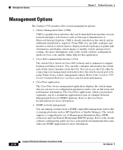
... network. The switch exits Express Setup mode. Your switch is connected the network. Enter the IP address of your switch: Step 1 Step 2 Launch a web browser on your switch (for example: 172.20.139.142.) The switch home page appears, as shown in Figure 1-8. 1-10 Catalyst 3750 Switch Hardware Installation Guide 78-15136-02 Enter a password in the Telnet Password field. SNMP community strings authenticate access to configure Simple Network Management Protocol (SNMP). If you set the SNMP write community, users can access...
... network. The switch exits Express Setup mode. Your switch is connected the network. Enter the IP address of your switch: Step 1 Step 2 Launch a web browser on your switch (for example: 172.20.139.142.) The switch home page appears, as shown in Figure 1-8. 1-10 Catalyst 3750 Switch Hardware Installation Guide 78-15136-02 Enter a password in the Telnet Password field. SNMP community strings authenticate access to configure Simple Network Management Protocol (SNMP). If you set the SNMP write community, users can access...

Hardware Installation Guide
Page 46
... the CLI to workstations, servers, routers, and Cisco IP Phones, be sure that both devices support and full-duplex transmission if the attached device supports it) and configures itself accordingly. In all cases, the attached device must be sure to the switch software configuration guide or the switch command reference. When the automatic crossover feature is a straight-through cable. Catalyst 3750 Switch Hardware Installation Guide 2-6 78-15136-02 When connecting the switch to enable the...
... the CLI to workstations, servers, routers, and Cisco IP Phones, be sure that both devices support and full-duplex transmission if the attached device supports it) and configures itself accordingly. In all cases, the attached device must be sure to the switch software configuration guide or the switch command reference. When the automatic crossover feature is a straight-through cable. Catalyst 3750 Switch Hardware Installation Guide 2-6 78-15136-02 When connecting the switch to enable the...
Hardware Installation Guide
Page 51
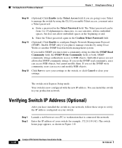
... Port Mode LEDs Mode LED STAT DUPLX Port Mode Port status Port duplex mode SPEED STACK Port speed Stack Member Status StackWise Port Status Description The port status. Table 2-5 Meaning of LED Colors in full-duplex mode. Green Link present. Error frames can remain amber for up to 30 seconds as excessive collisions, CRC errors, and alignment and jabber errors are monitored for possible loops. Off Port is operating in half duplex. Green Port is operating in full duplex. 78-15136-02 Catalyst 3750 Switch Hardware Installation Guide 2-11 The port duplex mode: full duplex...
... Port Mode LEDs Mode LED STAT DUPLX Port Mode Port status Port duplex mode SPEED STACK Port speed Stack Member Status StackWise Port Status Description The port status. Table 2-5 Meaning of LED Colors in full-duplex mode. Green Link present. Error frames can remain amber for up to 30 seconds as excessive collisions, CRC errors, and alignment and jabber errors are monitored for possible loops. Off Port is operating in half duplex. Green Port is operating in full duplex. 78-15136-02 Catalyst 3750 Switch Hardware Installation Guide 2-11 The port duplex mode: full duplex...

Hardware Installation Guide
Page 56
Use the supplied AC power cord to connect the AC power connector to the RPS receptacle. 2-16 Catalyst 3750 Switch Hardware Installation Guide 78-15136-02 Cisco RPS 300 The Cisco RPS 300 has two output levels: -48V and 12V with a total maximum output power of switches. Note The Cisco RPS 300 does not support the Catalyst 3750G-24TS switches. Cisco RPS Connector Specific Cisco RPS modes support specific Catalyst 3750 switches: • Cisco RPS 300 (model PWR300-AC-RPS-N1...
Use the supplied AC power cord to connect the AC power connector to the RPS receptacle. 2-16 Catalyst 3750 Switch Hardware Installation Guide 78-15136-02 Cisco RPS 300 The Cisco RPS 300 has two output levels: -48V and 12V with a total maximum output power of switches. Note The Cisco RPS 300 does not support the Catalyst 3750G-24TS switches. Cisco RPS Connector Specific Cisco RPS modes support specific Catalyst 3750 switches: • Cisco RPS 300 (model PWR300-AC-RPS-N1...
Hardware Installation Guide
Page 58
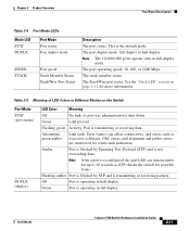
... Cisco.com for this application. • Cisco IOS command-line interface (CLI) The switch CLI is based on the switch, and no additional installation is required. Refer to modify switch- From CMS, you purchase separately, can manage switches from anywhere in your SNMP application for more information. 2-18 Catalyst 3750 Switch Hardware Installation Guide 78-15136-02 and port-level settings. The CiscoView application, which you can use to the CiscoView documentation for more information. • SNMP network management...
... Cisco.com for this application. • Cisco IOS command-line interface (CLI) The switch CLI is based on the switch, and no additional installation is required. Refer to modify switch- From CMS, you purchase separately, can manage switches from anywhere in your SNMP application for more information. 2-18 Catalyst 3750 Switch Hardware Installation Guide 78-15136-02 and port-level settings. The CiscoView application, which you can use to the CiscoView documentation for more information. • SNMP network management...

Hardware Installation Guide
Page 71
..., the Status, the Duplex LEDs turn amber for 2 seconds. The MASTR LED is complete, only the SYST and STAT LEDs are installing the Catalyst 3750-24TS, 3750G-24T, 3750G-12S, or 3750-48TS switches, you can use the Cisco RPS 675. Powering Off the Switch and Disconnecting the Console Port Disconnect the power cord from the switch console port. Chapter 3 Switch Installation Preparing for Installation Step 3 Connect the other LEDs turn off. Install the switch in the "Installing the Switch" section on a stack master switch...
..., the Status, the Duplex LEDs turn amber for 2 seconds. The MASTR LED is complete, only the SYST and STAT LEDs are installing the Catalyst 3750-24TS, 3750G-24T, 3750G-12S, or 3750-48TS switches, you can use the Cisco RPS 675. Powering Off the Switch and Disconnecting the Console Port Disconnect the power cord from the switch console port. Chapter 3 Switch Installation Preparing for Installation Step 3 Connect the other LEDs turn off. Install the switch in the "Installing the Switch" section on a stack master switch...

Hardware Installation Guide
Page 90
...-panel ports. Use the supplied black screw, as shown in Figure 3-28 and Figure 3-29 to attach the cable guide to the switch software configuration guide or the switch command reference. For configuration information, refer to the left or right bracket. 3-30 Catalyst 3750 Switch Hardware Installation Guide 78-15136-02 See the "Connecting StackWise Cable to StackWise Ports" section on page 3-37. • Connect to a Power Source" section on page 1-6. See the "Connecting to the console port...
...-panel ports. Use the supplied black screw, as shown in Figure 3-28 and Figure 3-29 to attach the cable guide to the switch software configuration guide or the switch command reference. For configuration information, refer to the left or right bracket. 3-30 Catalyst 3750 Switch Hardware Installation Guide 78-15136-02 See the "Connecting StackWise Cable to StackWise Ports" section on page 3-37. • Connect to a Power Source" section on page 1-6. See the "Connecting to the console port...

Hardware Installation Guide
Page 96
... setup program. To use CMS, go to the front-panel ports. For configuration information, refer to the Console Port" section on page 1-4 and the "Starting the Terminal Emulation Software" section on page 1-6. • Power on page 1-6. See the "Connecting to the switch software configuration guide or the switch command reference. See the "Completing the Setup Program" section on page 3-46 to the front-panel ports. If the switches are stacked, see the "Powering...
... setup program. To use CMS, go to the front-panel ports. For configuration information, refer to the Console Port" section on page 1-4 and the "Starting the Terminal Emulation Software" section on page 1-6. • Power on page 1-6. See the "Connecting to the switch software configuration guide or the switch command reference. See the "Completing the Setup Program" section on page 3-46 to the front-panel ports. If the switches are stacked, see the "Powering...

Hardware Installation Guide
Page 97
... other switch, and secure the screws tightly. Caution Removing and installing the StackWise cable can shorten its useful life. Chapter 3 Switch Installation Connecting StackWise Cable to the "Launching the Switch Home Page" section on page C-3. To use CMS, go to StackWise Ports To use a Cisco-approved StackWise cable to connect the switches. Note Always use the CLI, enter commands at the Switch> prompt through the console port by using a terminal program or through the network by using Telnet.
... other switch, and secure the screws tightly. Caution Removing and installing the StackWise cable can shorten its useful life. Chapter 3 Switch Installation Connecting StackWise Cable to the "Launching the Switch Home Page" section on page C-3. To use CMS, go to StackWise Ports To use a Cisco-approved StackWise cable to connect the switches. Note Always use the CLI, enter commands at the Switch> prompt through the console port by using a terminal program or through the network by using Telnet.

Hardware Installation Guide
Page 111
..., page 4-1 • Clearing the Switch IP Address and Configuration, page 4-2 • Replacing a Failed Stack Member, page 4-7 Understanding POST Results As the switch powers on page 2-8. CH A P T E R 4 Troubleshooting The LEDs on the front panel provide troubleshooting information about the switch. You can also get statistics from the browser interface, from the command-line interface (CLI), or from a Simple Network Management Protocol (SNMP) workstation. The Speed and the Stack LEDs turn amber for 2 seconds. 78-15136-02 Catalyst 3750 Switch Hardware Installation Guide 4-1
..., page 4-1 • Clearing the Switch IP Address and Configuration, page 4-2 • Replacing a Failed Stack Member, page 4-7 Understanding POST Results As the switch powers on page 2-8. CH A P T E R 4 Troubleshooting The LEDs on the front panel provide troubleshooting information about the switch. You can also get statistics from the browser interface, from the command-line interface (CLI), or from a Simple Network Management Protocol (SNMP) workstation. The Speed and the Stack LEDs turn amber for 2 seconds. 78-15136-02 Catalyst 3750 Switch Hardware Installation Guide 4-1
Hardware Installation Guide
Page 143
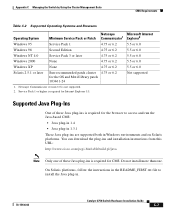
... 1.3.1 These Java plug-ins are supported both in . 78-15136-02 Catalyst 3750 Switch Hardware Installation Guide C-7 Supported Java Plug-Ins One of these Java plug-ins is required for the browser to install the Java plug-in Windows environments and on Solaris platforms. You can download the plug-ins and installation instructions from this URL: http://www.cisco.com/pcgi-bin/tablebuild.pl/java...
... 1.3.1 These Java plug-ins are supported both in . 78-15136-02 Catalyst 3750 Switch Hardware Installation Guide C-7 Supported Java Plug-Ins One of these Java plug-ins is required for the browser to install the Java plug-in Windows environments and on Solaris platforms. You can download the plug-ins and installation instructions from this URL: http://www.cisco.com/pcgi-bin/tablebuild.pl/java...
Hardware Installation Guide
Page 156
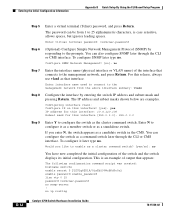
... D Quick Setup By Using the CLI-Based Setup Program D-12 Step 5 Enter a virtual terminal (Telnet) password, and press Return. Enter virtual terminal password: terminal-password Step 6 (Optional) Configure Simple Network Management Protocol (SNMP) by entering the switch IP address and subnet mask and pressing Return. Enter interface name used to connect to the management network from 1 to configure the switch as that appears: The following configuration command script was created: hostname switch1 enable secret 5 $1$Ulq8$DlA/OiaEbl90WcBPd9cOn1 enable password enable_password line vty...
... D Quick Setup By Using the CLI-Based Setup Program D-12 Step 5 Enter a virtual terminal (Telnet) password, and press Return. Enter virtual terminal password: terminal-password Step 6 (Optional) Configure Simple Network Management Protocol (SNMP) by entering the switch IP address and subnet mask and pressing Return. Enter interface name used to connect to the management network from 1 to configure the switch as that appears: The following configuration command script was created: hostname switch1 enable secret 5 $1$Ulq8$DlA/OiaEbl90WcBPd9cOn1 enable password enable_password line vty...
Hardware Installation Guide
Page 157
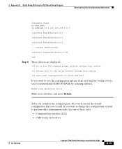
... want to change this configuration to save it the next time the switch reboots, save the configuration and use one of these tools: • Command-line interface (CLI) • CMS from your selection, and press Return. If you created. Enter your selection [2]:2 Make your browser 78-15136-02 Catalyst 3750 Switch Hardware Installation Guide D-13 end Step 10 These choices are displayed: [0] Go to the IOS command prompt without saving this config. [1] Return...
... want to change this configuration to save it the next time the switch reboots, save the configuration and use one of these tools: • Command-line interface (CLI) • CMS from your selection, and press Return. If you created. Enter your selection [2]:2 Make your browser 78-15136-02 Catalyst 3750 Switch Hardware Installation Guide D-13 end Step 10 These choices are displayed: [0] Go to the IOS command prompt without saving this config. [1] Return...

Hardware Installation Guide
Page 194
... software D-9 table or shelf-mounting 3-36 wall mounting 3-32 warning E-5 See also procedures installing or replacing the unit warning E-12 installing SFP modules 3-41 to 3-43 IOS command-line interface 2-18 IP address configuring by using Express Setup 1-9 verifying 1-10 to 1-11 J jewelry removal warning E-6 L laser beam exposure warning E-30 laser radiation warning E-31 LEDs color meanings 2-10 duplex 2-11 front panel 2-8 interpreting 2-10 master 2-10 port 2-10 to 2-12 port mode...
... software D-9 table or shelf-mounting 3-36 wall mounting 3-32 warning E-5 See also procedures installing or replacing the unit warning E-12 installing SFP modules 3-41 to 3-43 IOS command-line interface 2-18 IP address configuring by using Express Setup 1-9 verifying 1-10 to 1-11 J jewelry removal warning E-6 L laser beam exposure warning E-30 laser radiation warning E-31 LEDs color meanings 2-10 duplex 2-11 front panel 2-8 interpreting 2-10 master 2-10 port 2-10 to 2-12 port mode...


