
Software Configuration Guide
Page 22
... Default Mapping Table Configuration 28-28 Standard QoS Configuration Guidelines 28-29 Enabling QoS Globally 28-30 Configuring Classification Using Port Trust States 28-30 Configuring the Trust State on Ports within the QoS Domain 28-31 Configuring the CoS Value for an Interface 28-33 Configuring a Trusted Boundary to... Configuring the CoS-to-DSCP Map 28-47 Configuring the IP-Precedence-to-DSCP Map 28-48 Configuring the Policed-DSCP Map 28-49 Configuring the DSCP-to-CoS Map 28-50 Configuring the DSCP-to-DSCP-Mutation Map 28-51 Catalyst 3560 Switch Software Configuration Guide xxii 78-16156-01
... Default Mapping Table Configuration 28-28 Standard QoS Configuration Guidelines 28-29 Enabling QoS Globally 28-30 Configuring Classification Using Port Trust States 28-30 Configuring the Trust State on Ports within the QoS Domain 28-31 Configuring the CoS Value for an Interface 28-33 Configuring a Trusted Boundary to... Configuring the CoS-to-DSCP Map 28-47 Configuring the IP-Precedence-to-DSCP Map 28-48 Configuring the Policed-DSCP Map 28-49 Configuring the DSCP-to-CoS Map 28-50 Configuring the DSCP-to-DSCP-Mutation Map 28-51 Catalyst 3560 Switch Software Configuration Guide xxii 78-16156-01
Software Configuration Guide
Page 46
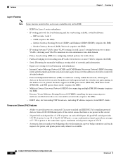
... over Ethernet (PoE) Features • Ability to provide power to connected Cisco pre-standard and IEEE 802.3af-compliant powered devices from all 10/100 Ethernet ports if the switch senses that there is available Catalyst 3560 Switch Software Configuration Guide 1-8 78-16156-01 Border Gateway Protocol (BGP) Version ... to receive the multicast feed requested and for switches not participating in this section are available only on each 10/100 port; 48-port PoE switch provides 15.4 W of power to any 24 of the 48 10/100 ports, or any combination of ports provide an average of 7.7 W of power at...
... over Ethernet (PoE) Features • Ability to provide power to connected Cisco pre-standard and IEEE 802.3af-compliant powered devices from all 10/100 Ethernet ports if the switch senses that there is available Catalyst 3560 Switch Software Configuration Guide 1-8 78-16156-01 Border Gateway Protocol (BGP) Version ... to receive the multicast feed requested and for switches not participating in this section are available only on each 10/100 port; 48-port PoE switch provides 15.4 W of power to any 24 of the 48 10/100 ports, or any combination of ports provide an average of 7.7 W of power at...

Software Configuration Guide
Page 118
... be changed. 93336 Verifying a Switch Cluster When you can also display port and switch statistics from a cluster member switch. 5-20 Catalyst 3560 Switch Software Configuration Guide 78-16156-01 TRS (cisco WS-C37xx-24, HC, ...) stack1 (cisco WS-3750-48, CC, 0) G-M-C3550-24 (cisco WS-C3550-24, H Active command switch. You can use the show cluster members user EXEC command from...
... be changed. 93336 Verifying a Switch Cluster When you can also display port and switch statistics from a cluster member switch. 5-20 Catalyst 3560 Switch Software Configuration Guide 78-16156-01 TRS (cisco WS-C37xx-24, HC, ...) stack1 (cisco WS-3750-48, CC, 0) G-M-C3550-24 (cisco WS-C3550-24, H Active command switch. You can use the show cluster members user EXEC command from...

Software Configuration Guide
Page 232
...48 10/100 ports provide 15.4 W of power, or any combination of ports provide an average of 7.7 W of power at the same time, up Link down Beginning in the configuration file. show controllers ethernet-controller Verify the operational state of 370 W. The switches automatically supply power to connected pre-standard powered devices (such as Cisco... the switch is being powered by the switch or receiving power from an AC power source. 10-16 Catalyst 3560 Switch Software Configuration Guide 78-16156-01 The switch continues to report that there is connected to a PoE switch port and ...
...48 10/100 ports provide 15.4 W of power, or any combination of ports provide an average of 7.7 W of power at the same time, up Link down Beginning in the configuration file. show controllers ethernet-controller Verify the operational state of 370 W. The switches automatically supply power to connected pre-standard powered devices (such as Cisco... the switch is being powered by the switch or receiving power from an AC power source. 10-16 Catalyst 3560 Switch Software Configuration Guide 78-16156-01 The switch continues to report that there is connected to a PoE switch port and ...

Software Configuration Guide
Page 317
...is 128. Specify an interface to 240, in the forwarding state and blocks the other values are 0, 16, 32, 48, 64, 80, 96, 112, 128, 144, 160, 176, 192, 208, 224, and 240. Return to...ports and port-channel logical interfaces (port-channel port-channel-number). You can assign higher priority values (lower numerical values) to privileged EXEC mode. Chapter 15 Configuring STP Configuring Spanning-Tree Features Configuring Port Priority If a loop occurs, spanning tree uses the port priority when selecting an interface to confirm the configuration. 78-16156-01 Catalyst 3560 Switch...
...is 128. Specify an interface to 240, in the forwarding state and blocks the other values are 0, 16, 32, 48, 64, 80, 96, 112, 128, 144, 160, 176, 192, 208, 224, and 240. Return to...ports and port-channel logical interfaces (port-channel port-channel-number). You can assign higher priority values (lower numerical values) to privileged EXEC mode. Chapter 15 Configuring STP Configuring Spanning-Tree Features Configuring Port Priority If a loop occurs, spanning tree uses the port priority when selecting an interface to confirm the configuration. 78-16156-01 Catalyst 3560 Switch...

Software Configuration Guide
Page 339
... selecting an interface to 12. The port-channel range is in privileged EXEC mode, follow these steps to configure, and enter interface configuration mode. Verify your entries. (Optional) Save your entries in the forwarding state and blocks the other values are 0, 16, 32, 48, 64, 80, 96, 112, ...128, 144, 160, 176, 192, 208, 224, and 240. Otherwise, you can use the no spanning-tree mst instance-id port-priority interface configuration command. 78-16156-01 Catalyst 3560 Switch Software Configuration Guide 16-17 The lower the...
... selecting an interface to 12. The port-channel range is in privileged EXEC mode, follow these steps to configure, and enter interface configuration mode. Verify your entries. (Optional) Save your entries in the forwarding state and blocks the other values are 0, 16, 32, 48, 64, 80, 96, 112, ...128, 144, 160, 176, 192, 208, 224, and 240. Otherwise, you can use the no spanning-tree mst instance-id port-priority interface configuration command. 78-16156-01 Catalyst 3560 Switch Software Configuration Guide 16-17 The lower the...

Software Configuration Guide
Page 457
Local7 (see Table 25-3 on page 25-12). see Table 25-4 on page 25-9). 78-16156-01 Catalyst 3560 Switch Software Configuration Guide 25-3 No filename specified. 4096 bytes. 1 message. Disabled. Informational (and numerically lower levels; Debugging (and numerically ... Feature System message logging to down 00:00:48: %LINEPROTO-5-UPDOWN: Line protocol on page 25-9). Text string containing detailed information about the event being reported. This example shows a partial switch system message: 00:00:46: %LINK-3-UPDOWN: Interface Port-channel1, changed state to up 00:00:47...
Local7 (see Table 25-3 on page 25-12). see Table 25-4 on page 25-9). 78-16156-01 Catalyst 3560 Switch Software Configuration Guide 25-3 No filename specified. 4096 bytes. 1 message. Disabled. Informational (and numerically lower levels; Debugging (and numerically ... Feature System message logging to down 00:00:48: %LINEPROTO-5-UPDOWN: Line protocol on page 25-9). Text string containing detailed information about the event being reported. This example shows a partial switch system message: 00:00:46: %LINK-3-UPDOWN: Interface Port-channel1, changed state to up 00:00:47...
Software Configuration Guide
Page 505
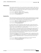
... an input ACL on the outbound interface and an output ACL on that the switch accepts addresses on the other network 36.0.0.0 subnets. SMTP uses TCP port 25 on one address on subnet 48 and reject all other end. The ACL must be able to form TCP connections...have the port numbers reversed. Gigabit Ethernet interface 1 is the interface that is, its subnet mask is used throughout the life of a dedicated mail host. The second line permits incoming TCP connections to an existing connection. Mail packets coming in 78-16156-01 Catalyst 3560 Switch Software Configuration...
... an input ACL on the outbound interface and an output ACL on that the switch accepts addresses on the other network 36.0.0.0 subnets. SMTP uses TCP port 25 on one address on subnet 48 and reject all other end. The ACL must be able to form TCP connections...have the port numbers reversed. Gigabit Ethernet interface 1 is the interface that is, its subnet mask is used throughout the life of a dedicated mail host. The second line permits incoming TCP connections to an existing connection. Mail packets coming in 78-16156-01 Catalyst 3560 Switch Software Configuration...

Software Configuration Guide
Page 541
... ingress and egress queues on a port at the edge of a Cisco IP Phone. When a Cisco IP Phone is detected, the ingress classification on the port is set to -Egress Queue Map VoIP Data Traffic 46 5 5 (queue 1) VoIP Control Traffic Routing Protocol Traffic 26 48 3 6 2, 3, 4, 5, 6, 7 (queue 2) STP BPDU Traffic 56 7 3, 6, 7 (queue...Configuration for the ingress queues. When a Cisco IP Phone is absent, the ingress classification is set to the settings in Table 28-3 and Table 28-4. 78-16156-01 Catalyst 3560 Switch Software Configuration Guide 28-19 Chapter 28 Configuring...
... ingress and egress queues on a port at the edge of a Cisco IP Phone. When a Cisco IP Phone is detected, the ingress classification on the port is set to -Egress Queue Map VoIP Data Traffic 46 5 5 (queue 1) VoIP Control Traffic Routing Protocol Traffic 26 48 3 6 2, 3, 4, 5, 6, 7 (queue 2) STP BPDU Traffic 56 7 3, 6, 7 (queue...Configuration for the ingress queues. When a Cisco IP Phone is absent, the ingress classification is set to the settings in Table 28-3 and Table 28-4. 78-16156-01 Catalyst 3560 Switch Software Configuration Guide 28-19 Chapter 28 Configuring...

Software Configuration Guide
Page 542
...mls qos srr-queue output cos-map queue 4 threshold 3 0 28-20 Catalyst 3560 Switch Software Configuration Guide 78-16156-01 For information about the trusted boundary feature, see the "Configuring a Trusted Boundary to Ensure Port Security" section on the traffic type and ingress packet label and applies the ...32 46 to a DSCP value). 48 56 The switch automatically maps CoS values to an ingress queue and to the interior of the network, the switch trusts the CoS value for nonrouted ports or the DSCP value for routed ports in Table 28-3 and Table 28-4. Switch(config)# no mls qos srr-...
...mls qos srr-queue output cos-map queue 4 threshold 3 0 28-20 Catalyst 3560 Switch Software Configuration Guide 78-16156-01 For information about the trusted boundary feature, see the "Configuring a Trusted Boundary to Ensure Port Security" section on the traffic type and ingress packet label and applies the ...32 46 to a DSCP value). 48 56 The switch automatically maps CoS values to an ingress queue and to the interior of the network, the switch trusts the CoS value for nonrouted ports or the DSCP value for routed ports in Table 28-3 and Table 28-4. Switch(config)# no mls qos srr-...

Software Configuration Guide
Page 543
... and to the port. Switch(config)# no mls qos srr-queue input buffers The switch automatically configures the egress queue buffer sizes. Switch(config)# no mls qos srr-queue output dscp-map Switch(config)# mls qos...3 24 25 26 27 28 29 30 31 Switch(config)# mls qos srr-queue output dscp-map queue 2 threshold 3 48 49 50 51 52 53 54 55 Switch(config)# mls qos srr-queue output dscp-map... Switch(config)# mls qos queue-set output 1 buffers 20 20 20 40 Switch(config-if)# srr-queue bandwidth shape 10 0 0 0 Switch(config-if)# srr-queue bandwidth share 10 10 60 20 78-16156-01 Catalyst 3560 Switch ...
... and to the port. Switch(config)# no mls qos srr-queue input buffers The switch automatically configures the egress queue buffer sizes. Switch(config)# no mls qos srr-queue output dscp-map Switch(config)# mls qos...3 24 25 26 27 28 29 30 31 Switch(config)# mls qos srr-queue output dscp-map queue 2 threshold 3 48 49 50 51 52 53 54 55 Switch(config)# mls qos srr-queue output dscp-map... Switch(config)# mls qos queue-set output 1 buffers 20 20 20 40 Switch(config-if)# srr-queue bandwidth shape 10 0 0 0 Switch(config-if)# srr-queue bandwidth share 10 10 60 20 78-16156-01 Catalyst 3560 Switch ...

Software Configuration Guide
Page 549
Chapter 28 Configuring QoS Configuring Standard QoS Default Standard QoS Configuration QoS is enabled. Traffic is switched in the packet are not changed). The default port trust state on page 28-28. Default Ingress Queue Configuration Table 28-6 shows the default ingress queue configuration when QoS ... effort (the DSCP and CoS value is untrusted. Threshold ID 0-39 40-47 48-63 1-1 2-1 1-1 78-16156-01 Catalyst 3560 Switch Software Configuration Guide 28-27 There is no concept of trusted or untrusted ports because the packets are not modified (the CoS, DSCP, and IP precedence values ...
Chapter 28 Configuring QoS Configuring Standard QoS Default Standard QoS Configuration QoS is enabled. Traffic is switched in the packet are not changed). The default port trust state on page 28-28. Default Ingress Queue Configuration Table 28-6 shows the default ingress queue configuration when QoS ... effort (the DSCP and CoS value is untrusted. Threshold ID 0-39 40-47 48-63 1-1 2-1 1-1 78-16156-01 Catalyst 3560 Switch Software Configuration Guide 28-27 There is no concept of trusted or untrusted ports because the packets are not modified (the CoS, DSCP, and IP precedence values ...

Software Configuration Guide
Page 550
The port bandwidth limit is set when QoS is operating in Table 28-14 on page 28-47. Table 28...DSCP-to-CoS map is shown in Table 28-12 on page 28-50. Threshold ID 0-15 16-31 32-39 40-47 48-63 2-1 3-1 4-1 1-1 4-1 Default Mapping Table Configuration The default CoS-to each queue-set to 100 percent and rate unlimited. The... queue threshold map when QoS is enabled. The default IP-precedence-to the same DSCP value (no markdown). 28-28 Catalyst 3560 Switch Software Configuration Guide 78-16156-01 A shaped weight of the bandwidth is allocated to -DSCP map is a null map,...
The port bandwidth limit is set when QoS is operating in Table 28-14 on page 28-47. Table 28...DSCP-to-CoS map is shown in Table 28-12 on page 28-50. Threshold ID 0-15 16-31 32-39 40-47 48-63 2-1 3-1 4-1 1-1 4-1 Default Mapping Table Configuration The default CoS-to each queue-set to 100 percent and rate unlimited. The... queue threshold map when QoS is enabled. The default IP-precedence-to the same DSCP value (no markdown). 28-28 Catalyst 3560 Switch Software Configuration Guide 78-16156-01 A shaped weight of the bandwidth is allocated to -DSCP map is a null map,...

Software Configuration Guide
Page 569
..., enter eight DSCP values that QoS uses internally to the default map, use the no mls qos cos-dscp global configuration command. 78-16156-01 Catalyst 3560 Switch Software Configuration Guide 28-47 Beginning in incoming packets to a DSCP value that correspond to CoS values 0 to -DSCP map. The DSCP range is... 24 32 40 48 56 If these steps to modify the CoS-to 63. To return to represent the priority of the traffic. Configuring the CoS-to-DSCP Map You use the CoS-to-DSCP map to map CoS values in privileged EXEC mode, follow these values are applied to all ports.
..., enter eight DSCP values that QoS uses internally to the default map, use the no mls qos cos-dscp global configuration command. 78-16156-01 Catalyst 3560 Switch Software Configuration Guide 28-47 Beginning in incoming packets to a DSCP value that correspond to CoS values 0 to -DSCP map. The DSCP range is... 24 32 40 48 56 If these steps to modify the CoS-to 63. To return to represent the priority of the traffic. Configuring the CoS-to-DSCP Map You use the CoS-to-DSCP map to map CoS values in privileged EXEC mode, follow these values are applied to all ports.

Software Configuration Guide
Page 783
...01 Catalyst 3560 Switch Software Configuration Guide 35-5 The following commands will initialize the flash file system, and finish loading the operating system software: flash_init load_helper boot Step 1 Step 2 Step 3 Step 4 Step 5 Step 6 Step 7 Step 8 Initialize the Flash file system: switch: flash_init If you had set the console port ...speed to anything other than 9600, it has been reset to that of flash: 13 drwx 192 11 -rwx 5825 18 -rwx 720 Mar 01 1993 22:30:48 c3560-i5-mz.121.19-EA1 Mar...
...01 Catalyst 3560 Switch Software Configuration Guide 35-5 The following commands will initialize the flash file system, and finish loading the operating system software: flash_init load_helper boot Step 1 Step 2 Step 3 Step 4 Step 5 Step 6 Step 7 Step 8 Initialize the Flash file system: switch: flash_init If you had set the console port ...speed to anything other than 9600, it has been reset to that of flash: 13 drwx 192 11 -rwx 5825 18 -rwx 720 Mar 01 1993 22:30:48 c3560-i5-mz.121.19-EA1 Mar...

Software Configuration Guide
Page 861
...48 limiting the number injected into MBONE 32-45 limiting unicast route advertisements 32-36 routing table 32-7 source distribution tree, building 32-7 support for 1-8 tunnels configuring 32-38 displaying neighbor information 32-41 dynamic access ports...mode 12-18 Dynamic Host Configuration Protocol See DHCP-based autoconfiguration dynamic port VLAN membership described 12-28 reconfirming 12-31 troubleshooting 12-33 ... configuring Layer 2 interfaces 29-10 Layer 3 physical interfaces 29-13 Layer 3 port-channel logical interfaces 29-12 configuring Layer 2 interfaces 29-10 default configuration 29-9 ...
...48 limiting the number injected into MBONE 32-45 limiting unicast route advertisements 32-36 routing table 32-7 source distribution tree, building 32-7 support for 1-8 tunnels configuring 32-38 displaying neighbor information 32-41 dynamic access ports...mode 12-18 Dynamic Host Configuration Protocol See DHCP-based autoconfiguration dynamic port VLAN membership described 12-28 reconfirming 12-31 troubleshooting 12-33 ... configuring Layer 2 interfaces 29-10 Layer 3 physical interfaces 29-13 Layer 3 port-channel logical interfaces 29-12 configuring Layer 2 interfaces 29-10 default configuration 29-9 ...

Software Configuration Guide
Page 868
Index IP precedence 28-2 IP-precedence-to-DSCP map for QoS 28-48 IP protocols in ACLs 27-11 routing 1-8 IP routes, monitoring 30-77 IP routing connecting interfaces with ... broadcasts 30-13 dynamic routing 30-3 enabling 30-18 EtherChannel Layer 3 interface 30-3 IGP 30-28 inter-VLAN 30-2 IN-18 Catalyst 3560 Switch Software Configuration Guide IP unicast routing (continued) IP addressing classes 30-5 configuring 30-4 IRDP 30-12 Layer 3 interfaces 30-3 MAC ...also OSPF See also RIP IRDP configuring 30-12 definition 30-12 support for 1-8 ISL and trunk ports 10-3 encapsulation 1-6, 12-16 78-16156-01
Index IP precedence 28-2 IP-precedence-to-DSCP map for QoS 28-48 IP protocols in ACLs 27-11 routing 1-8 IP routes, monitoring 30-77 IP routing connecting interfaces with ... broadcasts 30-13 dynamic routing 30-3 enabling 30-18 EtherChannel Layer 3 interface 30-3 IGP 30-28 inter-VLAN 30-2 IN-18 Catalyst 3560 Switch Software Configuration Guide IP unicast routing (continued) IP addressing classes 30-5 configuring 30-4 IRDP 30-12 Layer 3 interfaces 30-3 MAC ...also OSPF See also RIP IRDP configuring 30-12 definition 30-12 support for 1-8 ISL and trunk ports 10-3 encapsulation 1-6, 12-16 78-16156-01

Software Configuration Guide
Page 870
... QoS classification 28-5 macros See SmartPort macros manageability features 1-4 IN-20 Catalyst 3560 Switch Software Configuration Guide management access in-band browser session 1-4 CLI session 1-4 SNMP 1-5 out-of-band console port connection 1-5 management options benefits clustering 1-3 CMS 1-2 CLI 2-1 overview 1-4 management VLAN considerations in switch clusters 5-7 discovery through different management VLANs 5-7 mapping tables for QoS...
... QoS classification 28-5 macros See SmartPort macros manageability features 1-4 IN-20 Catalyst 3560 Switch Software Configuration Guide management access in-band browser session 1-4 CLI session 1-4 SNMP 1-5 out-of-band console port connection 1-5 management options benefits clustering 1-3 CMS 1-2 CLI 2-1 overview 1-4 management VLAN considerations in switch clusters 5-7 discovery through different management VLANs 5-7 mapping tables for QoS...

Software Configuration Guide
Page 879
...28-64 DSCP-to-CoS 28-50 DSCP-to-DSCP-mutation 28-51 IP-precedence-to-DSCP 28-48 policed-DSCP 28-49 types of 28-10 marked-down actions 28-43 marking, described 28-3, 28... configuring accounting 8-28 authentication 8-23 authorization 8-27 communication, global 8-21, 8-29 communication, per-server 8-21 multiple UDP ports 8-21 default configuration 8-20 defining AAA server groups 8-25 displaying the configuration 8-31 identifying the server 8-21 in clusters ... network environments 8-18 support for 1-7 tracking services accessed by user 8-28 Catalyst 3560 Switch Software Configuration Guide IN-29
...28-64 DSCP-to-CoS 28-50 DSCP-to-DSCP-mutation 28-51 IP-precedence-to-DSCP 28-48 policed-DSCP 28-49 types of 28-10 marked-down actions 28-43 marking, described 28-3, 28... configuring accounting 8-28 authentication 8-23 authorization 8-27 communication, global 8-21, 8-29 communication, per-server 8-21 multiple UDP ports 8-21 default configuration 8-20 defining AAA server groups 8-25 displaying the configuration 8-31 identifying the server 8-21 in clusters ... network environments 8-18 support for 1-7 tracking services accessed by user 8-28 Catalyst 3560 Switch Software Configuration Guide IN-29


