
Hardware Installation Guide
Page 9
...Laser Beam Exposure Warning C-23 No On/Off Switch Warning C-24 Chassis Warning-Rack-Mounting and Servicing C-25 Reinforced Insulation Warning C-29 LAN Connections Only Warning C-30 No Field-Replaceable Units Warning C-31 Installation Warning C-32 SELV ...Source Warning C-33 Restricted Access Warning C-34 Shielded Ethernet Cables Warning C-35 Grounded Equipment Warning C-36 Ground Connection Warning C-37 Qualified Personnel Warning C-38 DC Power Disconnection Warning C-39 Exposed Wire Lead Warning C-41 Contents 78-6461-04 Catalyst...
...Laser Beam Exposure Warning C-23 No On/Off Switch Warning C-24 Chassis Warning-Rack-Mounting and Servicing C-25 Reinforced Insulation Warning C-29 LAN Connections Only Warning C-30 No Field-Replaceable Units Warning C-31 Installation Warning C-32 SELV ...Source Warning C-33 Restricted Access Warning C-34 Shielded Ethernet Cables Warning C-35 Grounded Equipment Warning C-36 Ground Connection Warning C-37 Qualified Personnel Warning C-38 DC Power Disconnection Warning C-39 Exposed Wire Lead Warning C-41 Contents 78-6461-04 Catalyst...

Hardware Installation Guide
Page 39
...slot). Module failed POST and should be replaced. Table 1-8 Expansion Slot LEDs Color Off Green Amber Expansion Slot Status No module is operating normally. Table 1-8 lists LED colors and their meanings. Rear-Panel Description Other than the Catalyst 2924M XL DC switch, the rear panels of installed modules.... 1 Product Overview Rear-Panel Description Module Slot LEDs Module slot LEDs (shown in Figure 1-6) show the status of a Catalyst 2900 XL and Catalyst 2900 LRE XL switches have an AC power connector, an RPS connector, and an RJ-45 console port. (See Figure 1-10 through Figure ...
...slot). Module failed POST and should be replaced. Table 1-8 Expansion Slot LEDs Color Off Green Amber Expansion Slot Status No module is operating normally. Table 1-8 lists LED colors and their meanings. Rear-Panel Description Other than the Catalyst 2924M XL DC switch, the rear panels of installed modules.... 1 Product Overview Rear-Panel Description Module Slot LEDs Module slot LEDs (shown in Figure 1-6) show the status of a Catalyst 2900 XL and Catalyst 2900 LRE XL switches have an AC power connector, an RPS connector, and an RJ-45 console port. (See Figure 1-10 through Figure ...

Hardware Installation Guide
Page 43
...Catalyst 2900 Series XL Hardware Installation Guide 1-23 For console port and adapter pinout information, see the "Connecting to a terminal. When the device internal power supply has been brought up or replaced, the RPS automatically stops powering the device. Warning Attach only the Cisco RPS (model PWR300-AC-RPS-N1) to one switch...receptacle. Chapter 1 Product Overview Power Connectors RPS Connector on the Catalyst 2912 LRE and 2924 LRE XL Switches The RPS is a 300W redundant power system that adapter from Cisco. It automatically senses when the power supply of a connected ...
...Catalyst 2900 Series XL Hardware Installation Guide 1-23 For console port and adapter pinout information, see the "Connecting to a terminal. When the device internal power supply has been brought up or replaced, the RPS automatically stops powering the device. Warning Attach only the Cisco RPS (model PWR300-AC-RPS-N1) to one switch...receptacle. Chapter 1 Product Overview Power Connectors RPS Connector on the Catalyst 2912 LRE and 2924 LRE XL Switches The RPS is a 300W redundant power system that adapter from Cisco. It automatically senses when the power supply of a connected ...
Hardware Installation Guide
Page 46
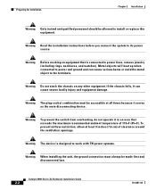
... to the terminals. Warning To prevent the switch from overheating, do not operate it can cause serious burns or weld the metal object to install or replace this equipment. To prevent airflow restriction, allow at all times because it serves as the main disconnecting device. Catalyst 2900 Series XL Hardware Installation Guide 2-2 78...
... to the terminals. Warning To prevent the switch from overheating, do not operate it can cause serious burns or weld the metal object to install or replace this equipment. To prevent airflow restriction, allow at all times because it serves as the main disconnecting device. Catalyst 2900 Series XL Hardware Installation Guide 2-2 78...

Hardware Installation Guide
Page 49
...type was sold or purchased by Information Technology Equipment (VCCI). If this equipment is used in a domestic environment, radio disturbance may be replaced with a residential-use . When such trouble occurs, the user may arise. Chapter 2 Installation Preparing for Installation Japan This is a ...Class A product based on the standard of the Voluntary Control Council for industrial use type. 78-6461-04 Catalyst 2900 Series XL Hardware Installation Guide 2-5 The seller or buyer should be required to take corrective actions. 46464 Korea Warning This is ...
...type was sold or purchased by Information Technology Equipment (VCCI). If this equipment is used in a domestic environment, radio disturbance may be replaced with a residential-use . When such trouble occurs, the user may arise. Chapter 2 Installation Preparing for Installation Japan This is a ...Class A product based on the standard of the Voluntary Control Council for industrial use type. 78-6461-04 Catalyst 2900 Series XL Hardware Installation Guide 2-5 The seller or buyer should be required to take corrective actions. 46464 Korea Warning This is ...
Hardware Installation Guide
Page 73
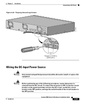
... circuit breaker to the OFF position, and tape the switch handle of the following procedures, ensure that power is removed from the DC circuit. DC INPUT Torque to 15 lbf-in. (240 ozf-in the OFF position. 78-6461-04 Catalyst 2900 Series XL Hardware Installation Guide 2-29 B +- Warning Before performing any... allowed to DC Power 74085 CONSOLE BERFEOFREERPOCTOWONEMNRAENCUTAINL G DC INPUT ICNUPRURTE: 3N6T:- 72 4-2A A +- Chapter 2 Installation Figure 2-20 Torquing Ground-Lug Screws Connecting to install or replace this equipment.
... circuit breaker to the OFF position, and tape the switch handle of the following procedures, ensure that power is removed from the DC circuit. DC INPUT Torque to 15 lbf-in. (240 ozf-in the OFF position. 78-6461-04 Catalyst 2900 Series XL Hardware Installation Guide 2-29 B +- Warning Before performing any... allowed to DC Power 74085 CONSOLE BERFEOFREERPOCTOWONEMNRAENCUTAINL G DC INPUT ICNUPRURTE: 3N6T:- 72 4-2A A +- Chapter 2 Installation Figure 2-20 Torquing Ground-Lug Screws Connecting to install or replace this equipment.
Hardware Installation Guide
Page 93
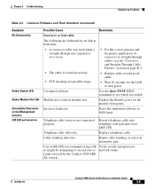
...on the module front panel. Corrupted software. Telephone cable loose or not connected properly. The following are indicated by the Catalyst 2900 LRE XL switch. Incorrect baud rate. Telephone cable defective. Cisco LRE CPE not communicating with a tested good cable. • Wait 30 seconds for the LED to 9600 baud. Module...Repair cable trunking or select an alternative pair. Tighten the thumb screws on the Management Console. LRE LED not turned on page B-3. • Replace with or might be attempting to see the "Crossover and Straight-Through Cable Pinouts" section on .
...on the module front panel. Corrupted software. Telephone cable loose or not connected properly. The following are indicated by the Catalyst 2900 LRE XL switch. Incorrect baud rate. Telephone cable defective. Cisco LRE CPE not communicating with a tested good cable. • Wait 30 seconds for the LED to 9600 baud. Module...Repair cable trunking or select an alternative pair. Tighten the thumb screws on the Management Console. LRE LED not turned on page B-3. • Replace with or might be attempting to see the "Crossover and Straight-Through Cable Pinouts" section on .