
Hardware Installation Guide
Page 6
... DC Power Connector 1-21 Cisco RPS Connector 1-22 Console Port 1-23 2 C H A P T E R Installation 2-1 Preparing for Installation 2-1 Warnings 2-1 EMC Regulatory Statements 2-4 U.S.A. 2-4 Taiwan 2-4 Japan 2-5 Korea 2-5 Hungary 2-6 Installation Guidelines 2-6 Verifying Package Contents 2-7 Installing the Switch on a Table or Shelf 2-9 Installing the Switch in a Rack 2-9 Removing Screws from the Switch 2-11 Attaching the Brackets to a Catalyst 2912 XL, 2924C XL...
... DC Power Connector 1-21 Cisco RPS Connector 1-22 Console Port 1-23 2 C H A P T E R Installation 2-1 Preparing for Installation 2-1 Warnings 2-1 EMC Regulatory Statements 2-4 U.S.A. 2-4 Taiwan 2-4 Japan 2-5 Korea 2-5 Hungary 2-6 Installation Guidelines 2-6 Verifying Package Contents 2-7 Installing the Switch on a Table or Shelf 2-9 Installing the Switch in a Rack 2-9 Removing Screws from the Switch 2-11 Attaching the Brackets to a Catalyst 2912 XL, 2924C XL...

Hardware Installation Guide
Page 7
...18 Attaching the Optional Cable Guide 2-19 Installing the Switch on a Wall 2-20 Attaching the Brackets to the Switch 2-21 Mounting the Switch to a Wall 2-22 Powering On the Switch and Running POST 2-24 Connecting to DC Power 2-25 Preparing for Installation 2-25 Grounding the Switch 2-26 Wiring the DC-Input Power Source 2-29... Correcting Module POST Failures 3-2 Diagnosing Problems 3-3 Technical Specifications A-1 Connectors and Cable Specifications B-1 Connector Specifications B-1 10/100 Ports B-1 100BASE-FX Ports B-2 Contents 78-6461-04 Catalyst 2900 Series XL Hardware Installation Guide vii
...18 Attaching the Optional Cable Guide 2-19 Installing the Switch on a Wall 2-20 Attaching the Brackets to the Switch 2-21 Mounting the Switch to a Wall 2-22 Powering On the Switch and Running POST 2-24 Connecting to DC Power 2-25 Preparing for Installation 2-25 Grounding the Switch 2-26 Wiring the DC-Input Power Source 2-29... Correcting Module POST Failures 3-2 Diagnosing Problems 3-3 Technical Specifications A-1 Connectors and Cable Specifications B-1 Connector Specifications B-1 10/100 Ports B-1 100BASE-FX Ports B-2 Contents 78-6461-04 Catalyst 2900 Series XL Hardware Installation Guide vii

Hardware Installation Guide
Page 9
INDEX Class 1 Laser Product Warning C-22 Laser Beam Exposure Warning C-23 No On/Off Switch Warning C-24 Chassis Warning-Rack-Mounting and Servicing C-25 Reinforced Insulation Warning C-29 LAN Connections Only Warning C-30 No Field-Replaceable Units Warning C-31 Installation ... Equipment Warning C-36 Ground Connection Warning C-37 Qualified Personnel Warning C-38 DC Power Disconnection Warning C-39 Exposed Wire Lead Warning C-41 Contents 78-6461-04 Catalyst 2900 Series XL Hardware Installation Guide ix
INDEX Class 1 Laser Product Warning C-22 Laser Beam Exposure Warning C-23 No On/Off Switch Warning C-24 Chassis Warning-Rack-Mounting and Servicing C-25 Reinforced Insulation Warning C-29 LAN Connections Only Warning C-30 No Field-Replaceable Units Warning C-31 Installation ... Equipment Warning C-36 Ground Connection Warning C-37 Qualified Personnel Warning C-38 DC Power Disconnection Warning C-39 Exposed Wire Lead Warning C-41 Contents 78-6461-04 Catalyst 2900 Series XL Hardware Installation Guide ix

Hardware Installation Guide
Page 11
... documents the hardware features of Ethernet and local area networking. Chapter 2, "Installation," provides the procedures for installing and configuring a Catalyst 2900 series XL switch. It describes the physical and performance characteristics of the switches, explains how to identify and resolve some of the problems that you are familiar with the concepts and terminology...
... documents the hardware features of Ethernet and local area networking. Chapter 2, "Installation," provides the procedures for installing and configuring a Catalyst 2900 series XL switch. It describes the physical and performance characteristics of the switches, explains how to identify and resolve some of the problems that you are familiar with the concepts and terminology...

Hardware Installation Guide
Page 12
Conventions This guide uses the following conventions and symbols: Note Means reader take note. Catalyst 2900 Series XL Hardware Installation Guide xii 78-6461-04 Examples use these conventions: • Terminal sessions and ...specifications for which you supply values are in italic. Appendix C, "Translated Safety Warnings," provides translations in boldface. • Arguments for the switches and the regulatory agency approvals. Notes, cautions, and warnings use the following conventions to convey instructions and information: Command descriptions use these conventions...
Conventions This guide uses the following conventions and symbols: Note Means reader take note. Catalyst 2900 Series XL Hardware Installation Guide xii 78-6461-04 Examples use these conventions: • Terminal sessions and ...specifications for which you supply values are in italic. Appendix C, "Translated Safety Warnings," provides translations in boldface. • Arguments for the switches and the regulatory agency approvals. Notes, cautions, and warnings use the following conventions to convey instructions and information: Command descriptions use these conventions...

Hardware Installation Guide
Page 15
..., or upgrading the switch, refer to change and therefore appear only in the "Obtaining Documentation" section on page xvi. • Release Notes for the Catalyst 2900 Series XL and Catalyst 3500 Series XL Switches (not orderable but is available on Cisco.com for initial configurations... and software upgrades tend to the release notes on Cisco.com) Note Switch requirements and procedures for the latest information....
..., or upgrading the switch, refer to change and therefore appear only in the "Obtaining Documentation" section on page xvi. • Release Notes for the Catalyst 2900 Series XL and Catalyst 3500 Series XL Switches (not orderable but is available on Cisco.com for initial configurations... and software upgrades tend to the release notes on Cisco.com) Note Switch requirements and procedures for the latest information....

Hardware Installation Guide
Page 16
... online help (available only from the switch CMS software) • Catalyst 2900 Series XL Hardware Installation Guide (order number DOC-786461=) • Catalyst 3500 Series XL Hardware Installation Guide (order number DOC-786456=) • Catalyst 2900 Series XL Modules Installation Guide (order...1000BASE-T Gigabit Interface Converter Installation Note (not orderable but is available on Cisco.com) • Catalyst GigaStack Gigabit Interface Converter Hardware Installation Guide (order number DOC-786460=) • Cisco LRE CPE Hardware Installation Guide (order number DOC-7811469=) • ...
... online help (available only from the switch CMS software) • Catalyst 2900 Series XL Hardware Installation Guide (order number DOC-786461=) • Catalyst 3500 Series XL Hardware Installation Guide (order number DOC-786456=) • Catalyst 2900 Series XL Modules Installation Guide (order...1000BASE-T Gigabit Interface Converter Installation Note (not orderable but is available on Cisco.com) • Catalyst GigaStack Gigabit Interface Converter Hardware Installation Guide (order number DOC-786460=) • Cisco LRE CPE Hardware Installation Guide (order number DOC-7811469=) • ...

Hardware Installation Guide
Page 21
... Catalyst 2900 series XL switches, hereafter referred to as the switches. • Switch features, including management options • Descriptions of the front and rear panels • Descriptions of the LEDs Features The switches are stackable 10/100 Ethernet switches to which you can be deployed as servers, routers, and other network devices. The switches can connect workstations, Cisco...
... Catalyst 2900 series XL switches, hereafter referred to as the switches. • Switch features, including management options • Descriptions of the front and rear panels • Descriptions of the LEDs Features The switches are stackable 10/100 Ethernet switches to which you can be deployed as servers, routers, and other network devices. The switches can connect workstations, Cisco...

Hardware Installation Guide
Page 22
...converter • On the Catalyst 2912 LRE XL and 2924 LRE XL switches, up to 24 LRE ports through one RJ-21 connector and hot swapping capability with the Cisco LRE customer premises equipment (CPE) devices • Supports up to 2048 MAC addresses on the Catalyst 2924 XL, 2924C XL,... and 2912 XL switches • Supports up to 8192 MAC addresses on the Catalyst 2924M XL, Catalyst 2924M XL DC and Catalyst 2912MF XL switches Figure 1-1 shows ...
...converter • On the Catalyst 2912 LRE XL and 2924 LRE XL switches, up to 24 LRE ports through one RJ-21 connector and hot swapping capability with the Cisco LRE customer premises equipment (CPE) devices • Supports up to 2048 MAC addresses on the Catalyst 2924 XL, 2924C XL,... and 2912 XL switches • Supports up to 8192 MAC addresses on the Catalyst 2924M XL, Catalyst 2924M XL DC and Catalyst 2912MF XL switches Figure 1-1 shows ...

Hardware Installation Guide
Page 23
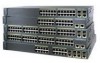
Chapter 1 Product Overview Figure 1-1 Catalyst 2900 Series XL Switches Version Number Description WS-C2912-LRE-XL 4 fixed autosensing 10/100 ports INPUT OUTPUT PWR PWR RESET TEMP FAN 9X 10X 11X 12X 12 LRE ports Cisco RPS 300 WS-C2924-LRE-XL 4 fixed autosensing 10/100 ports 24 LRE ports INPUT OUTPUT PWR PWR... 4 5 100BASE-FX 6 7 8 9 10 11 12 WS-C2924M-XL WS-C2924M-XLEM-DC 24 fixed autosensing 10/100 ports 2 expansion slots 12 MODE 1X 2X 3X Catalyst 2900 SERIES XL 4X 5X 6X 7X 8X 9X 10X 11X 100BaseFX 12X 13X 14X 15X 16X 17X 18X 19X 20X 21X 22X 23X 24X...
Chapter 1 Product Overview Figure 1-1 Catalyst 2900 Series XL Switches Version Number Description WS-C2912-LRE-XL 4 fixed autosensing 10/100 ports INPUT OUTPUT PWR PWR RESET TEMP FAN 9X 10X 11X 12X 12 LRE ports Cisco RPS 300 WS-C2924-LRE-XL 4 fixed autosensing 10/100 ports 24 LRE ports INPUT OUTPUT PWR PWR... 4 5 100BASE-FX 6 7 8 9 10 11 12 WS-C2924M-XL WS-C2924M-XLEM-DC 24 fixed autosensing 10/100 ports 2 expansion slots 12 MODE 1X 2X 3X Catalyst 2900 SERIES XL 4X 5X 6X 7X 8X 9X 10X 11X 100BaseFX 12X 13X 14X 15X 16X 17X 18X 19X 20X 21X 22X 23X 24X...

Hardware Installation Guide
Page 24
... You can also display network topologies to gather link information and to display switch images to the Catalyst 2900 Series XL and Catalyst 3500 Series XL Software Configuration Guide. You can manage the switch from an SNMP-compatible management station that can be launched from anywhere in your...up to twelve 100BASE-FX ports (See Figure 1-3), two module slots (see Figure 1-3), and up to the switch console port or by using Telnet from the CLI. Catalyst 2900 Series XL Hardware Installation Guide 1-4 78-6461-04 Front-Panel Description Chapter 1 Product Overview Management Interface Options...
... You can also display network topologies to gather link information and to display switch images to the Catalyst 2900 Series XL and Catalyst 3500 Series XL Software Configuration Guide. You can manage the switch from an SNMP-compatible management station that can be launched from anywhere in your...up to twelve 100BASE-FX ports (See Figure 1-3), two module slots (see Figure 1-3), and up to the switch console port or by using Telnet from the CLI. Catalyst 2900 Series XL Hardware Installation Guide 1-4 78-6461-04 Front-Panel Description Chapter 1 Product Overview Management Interface Options...

Hardware Installation Guide
Page 26
..., or 100 Mbps. When set for Cisco IP Phones and per-port priority override. Unlike the 3524-PWR XL switch, the Catalyst 2900 XL switches do not provide inline power. When connecting the switch to switches or hubs, use Category 3 and 4 cables. Cisco IP Phones-connected to the 10/100 ...port-must be connected to workstations, servers, routers, and Cisco IP Phones, be set ...
..., or 100 Mbps. When set for Cisco IP Phones and per-port priority override. Unlike the 3524-PWR XL switch, the Catalyst 2900 XL switches do not provide inline power. When connecting the switch to switches or hubs, use Category 3 and 4 cables. Cisco IP Phones-connected to the 10/100 ...port-must be connected to workstations, servers, routers, and Cisco IP Phones, be set ...

Hardware Installation Guide
Page 27
... LRE port must be connected to the patch panel through a private branch exchange (PBX) switch, a Cisco LRE 48 POTS Splitter can be over distances of up to the Cisco LRE CPE Hardware Installation Guide. If the other switch ports. Long-Reach Ethernet Ports The Long-Reach Ethernet (LRE) ports (Figure 1-4) use ... can be up to 1352 feet (412 meters). • If the switch port and the port on the same Catalyst 2900 LRE XL switch, and you can hot swap the CPE devices without powering down the switch or disrupting the other telephone services are configured for each CPE device can be...
... LRE port must be connected to the patch panel through a private branch exchange (PBX) switch, a Cisco LRE 48 POTS Splitter can be over distances of up to the Cisco LRE CPE Hardware Installation Guide. If the other switch ports. Long-Reach Ethernet Ports The Long-Reach Ethernet (LRE) ports (Figure 1-4) use ... can be up to 1352 feet (412 meters). • If the switch port and the port on the same Catalyst 2900 LRE XL switch, and you can hot swap the CPE devices without powering down the switch or disrupting the other telephone services are configured for each CPE device can be...

Hardware Installation Guide
Page 28
...above 700 kHz do not work when sharing a line with LRE signals. Each module port is internally switched to the patch panel. For more information about homologated POTS splitters, contact your Cisco sales representative. Note If a connection to a telephone network is not required, a splitter is not ... WS-X2922-XL-V WS-X2924-XL-V Catalyst 2900 Series XL Hardware Installation Guide 1-8 78-6461-04 For more information about the Cisco LRE 48 POTS Splitter (PS-1M-LRE-48), refer to digital PBX switches that the module slots support. Note Cisco Long-Reach Ethernet (LRE) products are ...
...above 700 kHz do not work when sharing a line with LRE signals. Each module port is internally switched to the patch panel. For more information about homologated POTS splitters, contact your Cisco sales representative. Note If a connection to a telephone network is not required, a splitter is not ... WS-X2922-XL-V WS-X2924-XL-V Catalyst 2900 Series XL Hardware Installation Guide 1-8 78-6461-04 For more information about the Cisco LRE 48 POTS Splitter (PS-1M-LRE-48), refer to digital PBX switches that the module slots support. Note Cisco Long-Reach Ethernet (LRE) products are ...

Hardware Installation Guide
Page 29
...XL WS-X2961-XL 1. These modules automatically configure themselves when you use the switch LEDs to 2048 MAC addresses. A power-on expansion modules for the Catalyst 2900 Series XL and Catalyst 3500 Series XL Switches. Catalyst 2900 Series XL Hardware Installation Guide 1-9 LEDs 78-6461-04 You can ... Configuration Guide for detailed information on self-test (POST) verifies that switch. If you install one of the LEDs and the Mode button that you insert them in a 2924M XL or Catalyst 2912MF XL switch (both supporting 8192 MAC addresses), the module fails POST. Note Modules...
...XL WS-X2961-XL 1. These modules automatically configure themselves when you use the switch LEDs to 2048 MAC addresses. A power-on expansion modules for the Catalyst 2900 Series XL and Catalyst 3500 Series XL Switches. Catalyst 2900 Series XL Hardware Installation Guide 1-9 LEDs 78-6461-04 You can ... Configuration Guide for detailed information on self-test (POST) verifies that switch. If you install one of the LEDs and the Mode button that you insert them in a 2924M XL or Catalyst 2912MF XL switch (both supporting 8192 MAC addresses), the module fails POST. Note Modules...

Hardware Installation Guide
Page 30
...Mode RPS button LED 47288 1-10 Catalyst 2900 Series XL Hardware Installation Guide 78-6461-04 The Catalyst 2900 Series XL and Catalyst 3500 Series XL Software Configuration Guide describes how to use CMS to manage standalone or individual switches and how to use cluster management ...software to manage switch clusters]. Front-Panel Description Chapter 1 Product...
...Mode RPS button LED 47288 1-10 Catalyst 2900 Series XL Hardware Installation Guide 78-6461-04 The Catalyst 2900 Series XL and Catalyst 3500 Series XL Software Configuration Guide describes how to use CMS to manage standalone or individual switches and how to use cluster management ...software to manage switch clusters]. Front-Panel Description Chapter 1 Product...

Hardware Installation Guide
Page 32
.... For information on the System LED colors during POST, see the "Powering On the Switch and Running POST" section on page 2-24. 1-12 Catalyst 2900 Series XL Hardware Installation Guide 78-6461-04 Front-Panel Description Figure 1-7 Catalyst 2912 LRE XL and 2924 LRE XL LEDs 10/100 port LEDs Chapter 1 Product Overview...
.... For information on the System LED colors during POST, see the "Powering On the Switch and Running POST" section on page 2-24. 1-12 Catalyst 2900 Series XL Hardware Installation Guide 78-6461-04 Front-Panel Description Figure 1-7 Catalyst 2912 LRE XL and 2924 LRE XL LEDs 10/100 port LEDs Chapter 1 Product Overview...

Hardware Installation Guide
Page 33
...is connected but is unavailable because it restarts. Pressing the Mode button on page 1-22. All other Catalyst 2900 XL and Catalyst 3500 XL switches use the Cisco RPS 300 (model PWR300-AC-RPS-N1). RPS is providing power to another device (redundancy has been ...allocated to the appropriate switch documentation for redundant power system (RPS) descriptions specific for the switch. Chapter 1 Product Overview Front-Panel Description RPS LED The Catalyst 2912 LRE XL and Catalyst 2924 LRE XL switches use the Cisco RPS 600 (model PWR600-AC-RPS). Refer...
...is connected but is unavailable because it restarts. Pressing the Mode button on page 1-22. All other Catalyst 2900 XL and Catalyst 3500 XL switches use the Cisco RPS 300 (model PWR300-AC-RPS-N1). RPS is providing power to another device (redundancy has been ...allocated to the appropriate switch documentation for redundant power system (RPS) descriptions specific for the switch. Chapter 1 Product Overview Front-Panel Description RPS LED The Catalyst 2912 LRE XL and Catalyst 2924 LRE XL switches use the Cisco RPS 600 (model PWR600-AC-RPS). Refer...

Hardware Installation Guide
Page 34
...This is in standby mode or in a fault condition. Front-Panel Description Chapter 1 Product Overview Table 1-3 RPS LED on the Catalyst 2912 LRE XL and 2924 LRE XL Switches (continued) Color Solid amber Blinking amber RPS Status The RPS is the default mode. The port modes (Table 1-4 and Table ... Cisco Systems. The internal power supply in use by the switch. (See Figure 1-8.) The port duplex mode: full duplex or half duplex, and default modes: • 10/100 ports: auto • 100BaseFX ports: auto • Gigabit ports: auto The port operating speed: 10 or 100 Mbps. 1-14 Catalyst 2900...
...This is in standby mode or in a fault condition. Front-Panel Description Chapter 1 Product Overview Table 1-3 RPS LED on the Catalyst 2912 LRE XL and 2924 LRE XL Switches (continued) Color Solid amber Blinking amber RPS Status The RPS is the default mode. The port modes (Table 1-4 and Table ... Cisco Systems. The internal power supply in use by the switch. (See Figure 1-8.) The port duplex mode: full duplex or half duplex, and default modes: • 10/100 ports: auto • 100BaseFX ports: auto • Gigabit ports: auto The port operating speed: 10 or 100 Mbps. 1-14 Catalyst 2900...

Hardware Installation Guide
Page 35
... half duplex. Note When the LRE mode is active, the 10/100 switch ports on all Catalyst 2900 XL and Catalyst 3500 XL switches except the Catalyst 2912 LRE XL and Catalyst 2924 LRE XL switches. Default mode on the Catalyst 2912 LRE XL and Catalyst 2924 LRE XL continue to show Ethernet link status. Default mode on these...
... half duplex. Note When the LRE mode is active, the 10/100 switch ports on all Catalyst 2900 XL and Catalyst 3500 XL switches except the Catalyst 2912 LRE XL and Catalyst 2924 LRE XL switches. Default mode on the Catalyst 2912 LRE XL and Catalyst 2924 LRE XL continue to show Ethernet link status. Default mode on these...


