
Hardware Installation Guide
Page 11
... Catalyst 2900 Series XL Hardware Installation Guide documents the hardware features of the switches, explains how to identify and resolve some of the problems that you are familiar with the concepts and terminology of Ethernet and local area networking. Chapter 3, "Troubleshooting," describes how to install a switch, and provides troubleshooting information and specifications. We assume that might arise when you are installing the switch. 78-6461-04 Catalyst 2900 Series XL Hardware Installation Guide...
... Catalyst 2900 Series XL Hardware Installation Guide documents the hardware features of the switches, explains how to identify and resolve some of the problems that you are familiar with the concepts and terminology of Ethernet and local area networking. Chapter 3, "Troubleshooting," describes how to install a switch, and provides troubleshooting information and specifications. We assume that might arise when you are installing the switch. 78-6461-04 Catalyst 2900 Series XL Hardware Installation Guide...

Hardware Installation Guide
Page 21
... servers, routers, and other network devices. CH A P T E R 1 Product Overview This chapter provides these features: • Autonegotiates speed and duplex operation on all 10/100 ports • Operates in full-duplex mode on all 100BASE-FX ports • Checks for errors on a received packet, determines the destination port, stores the packet in shared memory, and then forwards the packet to the destination port 78-6461-04 Catalyst 2900 Series XL Hardware Installation Guide...
... servers, routers, and other network devices. CH A P T E R 1 Product Overview This chapter provides these features: • Autonegotiates speed and duplex operation on all 10/100 ports • Operates in full-duplex mode on all 100BASE-FX ports • Checks for errors on a received packet, determines the destination port, stores the packet in shared memory, and then forwards the packet to the destination port 78-6461-04 Catalyst 2900 Series XL Hardware Installation Guide...

Hardware Installation Guide
Page 22
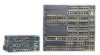
... RJ-21 connector and hot swapping capability with the Cisco LRE customer premises equipment (CPE) devices • Supports up to 2048 MAC addresses on the Catalyst 2924 XL, 2924C XL, and 2912 XL switches • Supports up to 8192 MAC addresses on the Catalyst 2924M XL, Catalyst 2924M XL DC and Catalyst 2912MF XL switches Figure 1-1 shows the switch models. Catalyst 2900 Series XL Hardware Installation Guide 1-2 78-6461-04
... RJ-21 connector and hot swapping capability with the Cisco LRE customer premises equipment (CPE) devices • Supports up to 2048 MAC addresses on the Catalyst 2924 XL, 2924C XL, and 2912 XL switches • Supports up to 8192 MAC addresses on the Catalyst 2924M XL, Catalyst 2924M XL DC and Catalyst 2912MF XL switches Figure 1-1 shows the switch models. Catalyst 2900 Series XL Hardware Installation Guide 1-2 78-6461-04

Hardware Installation Guide
Page 24
You can access the CLI either by connecting your network through a web browser such as Netscape Communicator or Microsoft Internet Explorer. and port-level settings. • Command-line Interface (CLI)-The switch IOS CLI software is a graphical user interface that is already installed on the model, the switch front panels can fully configure and monitor the switch and switch cluster members from a remote management station. • Simple network management protocol (SNMP)-SNMP provides a means to support desktop-switching features. For more information...
You can access the CLI either by connecting your network through a web browser such as Netscape Communicator or Microsoft Internet Explorer. and port-level settings. • Command-line Interface (CLI)-The switch IOS CLI software is a graphical user interface that is already installed on the model, the switch front panels can fully configure and monitor the switch and switch cluster members from a remote management station. • Simple network management protocol (SNMP)-SNMP provides a means to support desktop-switching features. For more information...

Hardware Installation Guide
Page 26
... XL switch, refer to the Catalyst 3500 Series XL Hardware Installation Guide. Catalyst 2900 Series XL Hardware Installation Guide 1-6 78-6461-04 Pinouts for Cisco IP Phones and per-port priority override. When set to operate in Appendix B, "Connectors and Cable Specifications." Cisco IP Phones-connected to the 10/100 port-must be connected to the Catalyst 2900 Series XL and Catalyst 3500 Series XL Software Configuration Guide for autonegotiation, the port senses the speed and duplex settings of half duplex, full duplex, 10...
... XL switch, refer to the Catalyst 3500 Series XL Hardware Installation Guide. Catalyst 2900 Series XL Hardware Installation Guide 1-6 78-6461-04 Pinouts for Cisco IP Phones and per-port priority override. When set to operate in Appendix B, "Connectors and Cable Specifications." Cisco IP Phones-connected to the 10/100 port-must be connected to the Catalyst 2900 Series XL and Catalyst 3500 Series XL Software Configuration Guide for autonegotiation, the port senses the speed and duplex settings of half duplex, full duplex, 10...

Hardware Installation Guide
Page 27
... configuring the LRE ports, refer to 4921 feet (1500 meters). The splitter routes LRE data (high-frequency) and voice (low-frequency) traffic from the telephone line to the Cisco LRE CPE Hardware Installation Guide. Long-Reach Ethernet Ports The Long-Reach Ethernet (LRE) ports (Figure 1-4) use 50/125- The default mode for full-duplex operation, the connection can be over distances of up to the patch panel through a basic telephone service...
... configuring the LRE ports, refer to 4921 feet (1500 meters). The splitter routes LRE data (high-frequency) and voice (low-frequency) traffic from the telephone line to the Cisco LRE CPE Hardware Installation Guide. Long-Reach Ethernet Ports The Long-Reach Ethernet (LRE) ports (Figure 1-4) use 50/125- The default mode for full-duplex operation, the connection can be over distances of up to the patch panel through a basic telephone service...

Hardware Installation Guide
Page 29
... and WS-X2922-XL support 2048 MAC addresses. For a complete list and the minimum software release required, refer to select a port mode. LEDs 78-6461-04 You can start the module by each port LED. If you insert them in a 2924M XL or Catalyst 2912MF XL switch (both supporting 8192 MAC addresses), the module fails POST. Catalyst 2900 Series XL Hardware Installation Guide 1-9 Changing a port mode changes the information provided by restarting that switch. The Ethernet Gigabit module supports several Gigabit Interface Converter (GBIC) devices...
... and WS-X2922-XL support 2048 MAC addresses. For a complete list and the minimum software release required, refer to select a port mode. LEDs 78-6461-04 You can start the module by each port LED. If you insert them in a 2924M XL or Catalyst 2912MF XL switch (both supporting 8192 MAC addresses), the module fails POST. Catalyst 2900 Series XL Hardware Installation Guide 1-9 Changing a port mode changes the information provided by restarting that switch. The Ethernet Gigabit module supports several Gigabit Interface Converter (GBIC) devices...

Hardware Installation Guide
Page 33
...-04 Catalyst 2900 Series XL Hardware Installation Guide 1-13 Table 1-2 and Table 1-3 list the RPS LED colors and their meanings. If the switch power supply fails, the switch powers down and after 15 seconds restarts, using power from the RPS. For more information see the "Cisco RPS Connector" section on the Catalyst 2912 XL, 2924C XL, 2924 XL, 2924MF XL, 2924M XL, and 2924M XL DC Switches Color Off Green Blinking green Amber RPS Status...
...-04 Catalyst 2900 Series XL Hardware Installation Guide 1-13 Table 1-2 and Table 1-3 list the RPS LED colors and their meanings. If the switch power supply fails, the switch powers down and after 15 seconds restarts, using power from the RPS. For more information see the "Cisco RPS Connector" section on the Catalyst 2912 XL, 2924C XL, 2924 XL, 2924MF XL, 2924M XL, and 2924M XL DC Switches Color Off Green Blinking green Amber RPS Status...

Hardware Installation Guide
Page 34
... mode is in standby mode or in use by the switch. (See Figure 1-8.) The port duplex mode: full duplex or half duplex, and default modes: • 10/100 ports: auto • 100BaseFX ports: auto • Gigabit ports: auto The port operating speed: 10 or 100 Mbps. 1-14 Catalyst 2900 Series XL Hardware Installation Guide 78-6461-04 Table 1-4 Port Mode LEDs on the RPS, and the LED should turn green. If it does not, the RPS fan could have a port LED. The port modes (Table 1-4 and Table 1-5) determine the type...
... mode is in standby mode or in use by the switch. (See Figure 1-8.) The port duplex mode: full duplex or half duplex, and default modes: • 10/100 ports: auto • 100BaseFX ports: auto • Gigabit ports: auto The port operating speed: 10 or 100 Mbps. 1-14 Catalyst 2900 Series XL Hardware Installation Guide 78-6461-04 Table 1-4 Port Mode LEDs on the RPS, and the LED should turn green. If it does not, the RPS fan could have a port LED. The port modes (Table 1-4 and Table 1-5) determine the type...
Hardware Installation Guide
Page 36
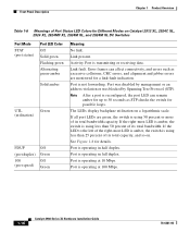
.... If all port LEDs are monitored for a link-fault indication. Port is not forwarding. Port is using less than 25 percent of its total bandwidth. Port was disabled by management or an address violation or was blocked by Spanning Tree Protocol (STP). Error frames can remain amber for up to the left of the right-most LED is amber, the switch is operating at 100 Mbps. 1-16 Catalyst 2900 Series XL Hardware Installation Guide 78-6461...
.... If all port LEDs are monitored for a link-fault indication. Port is not forwarding. Port is using less than 25 percent of its total bandwidth. Port was disabled by management or an address violation or was blocked by Spanning Tree Protocol (STP). Error frames can remain amber for up to the left of the right-most LED is amber, the switch is operating at 100 Mbps. 1-16 Catalyst 2900 Series XL Hardware Installation Guide 78-6461...
Hardware Installation Guide
Page 37
... port. DUPLX Blinking amber Cisco IOS Release 12.0(5.x)WC1/ WC21 Activity on the LRE port. Green LRE link present on the LRE CPE unable to a LRE CPE. Amber LRE port on the switch and WALL port on the LRE port. Green LRE port or remote CPE Ethernet port is operating in full-duplex mode. 78-6461-04 Catalyst 2900 Series XL Hardware Installation Guide 1-17 Chapter 1 Product Overview Front-Panel Description Table 1-7 Meanings of Port Status LEDs for LED...
... port. DUPLX Blinking amber Cisco IOS Release 12.0(5.x)WC1/ WC21 Activity on the LRE port. Green LRE link present on the LRE CPE unable to a LRE CPE. Amber LRE port on the switch and WALL port on the LRE port. Green LRE port or remote CPE Ethernet port is operating in full-duplex mode. 78-6461-04 Catalyst 2900 Series XL Hardware Installation Guide 1-17 Chapter 1 Product Overview Front-Panel Description Table 1-7 Meanings of Port Status LEDs for LED...

Hardware Installation Guide
Page 38
... a switch with this release or higher, use the Port Settings window or the show remote interfaces status user EXEC command. Green LRE port or remote CPE Ethernet port is operating at 100 Mbps. 1. Figure 1-9 Bandwidth Utilization 47293 SYSTEM 10BaseT/100BaseTx RPS 1x 2x 3x 4x 5x 6x 7x 8x MODE 9x 10x 11x 12x 6.25 -12.4%+ 12.5 -24%+ 25 - 49%+ 50%+ Catalyst 2900 SERIES XL 1-18 Catalyst 2900 Series XL Hardware Installation Guide...
... a switch with this release or higher, use the Port Settings window or the show remote interfaces status user EXEC command. Green LRE port or remote CPE Ethernet port is operating at 100 Mbps. 1. Figure 1-9 Bandwidth Utilization 47293 SYSTEM 10BaseT/100BaseTx RPS 1x 2x 3x 4x 5x 6x 7x 8x MODE 9x 10x 11x 12x 6.25 -12.4%+ 12.5 -24%+ 25 - 49%+ 50%+ Catalyst 2900 SERIES XL 1-18 Catalyst 2900 Series XL Hardware Installation Guide...

Hardware Installation Guide
Page 69
... Catalyst 2900 Series XL Hardware Installation Guide 2-25 In addition to determine a course of pressure • Panduit crimping tool with number 1, turn as the system completes a test. If a test fails, the port LED associated with a DC terminal block plug on the switch back panel. If POST fails, refer to Chapter 3, "Troubleshooting," to the items described in turn off . As each turn off in the Catalyst 2900 Series XL Installation Guide, the switch...
... Catalyst 2900 Series XL Hardware Installation Guide 2-25 In addition to determine a course of pressure • Panduit crimping tool with number 1, turn as the system completes a test. If a test fails, the port LED associated with a DC terminal block plug on the switch back panel. If POST fails, refer to Chapter 3, "Troubleshooting," to the items described in turn off . As each turn off in the Catalyst 2900 Series XL Installation Guide, the switch...

Hardware Installation Guide
Page 79
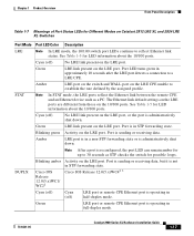
... their speed and duplex parameters manually set can explicitly set the speed and duplex parameters. If the attached ports do not autonegotiate or that do not support autonegotiation, you can reduce performance or result in the "Cable and Adapter Specifications" section on page B-4. 78-6461-04 Catalyst 2900 Series XL Hardware Installation Guide 2-35 When connecting to a 10/100 Port 74080 CONSOLE BERFEOFREERPOCTOWONEMNRAENCUTAINL G DC INPUT ICNUPRURTE: 3N6T:- 72 4-2A A +- Terminal block...
... their speed and duplex parameters manually set can explicitly set the speed and duplex parameters. If the attached ports do not autonegotiate or that do not support autonegotiation, you can reduce performance or result in the "Cable and Adapter Specifications" section on page B-4. 78-6461-04 Catalyst 2900 Series XL Hardware Installation Guide 2-35 When connecting to a 10/100 Port 74080 CONSOLE BERFEOFREERPOCTOWONEMNRAENCUTAINL G DC INPUT ICNUPRURTE: 3N6T:- 72 4-2A A +- Terminal block...
Hardware Installation Guide
Page 82
The port LED is amber while the STP discovers the topology and searches for solutions to the 100BASE-FX port of the cable to cabling problems. Reconfigure and reboot the connected device if necessary. Connecting to connect each 100BASE-FX port. This takes about 30 seconds, and then the port LED turns green. See Chapter 3, "Troubleshooting," for loops. If the port LED does not turn on, the device at the other end...
The port LED is amber while the STP discovers the topology and searches for solutions to the 100BASE-FX port of the cable to cabling problems. Reconfigure and reboot the connected device if necessary. Connecting to connect each 100BASE-FX port. This takes about 30 seconds, and then the port LED turns green. See Chapter 3, "Troubleshooting," for loops. If the port LED does not turn on, the device at the other end...
Hardware Installation Guide
Page 85
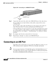
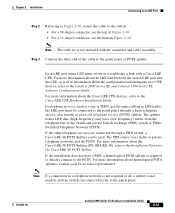
... devices, refer to the Installation Notes for the Cisco LRE 48 POTS Splitter. If telephone services, such as voice or ISDN, use the same cabling as LRE traffic, the LRE port must be used. Note The cable tie is required to directly connect to the patch panel or POTS splitter. Each LRE port status LED turns on when it establishes a link with the connector and cable assembly...
... devices, refer to the Installation Notes for the Cisco LRE 48 POTS Splitter. If telephone services, such as voice or ISDN, use the same cabling as LRE traffic, the LRE port must be used. Note The cable tie is required to directly connect to the patch panel or POTS splitter. Each LRE port status LED turns on when it establishes a link with the connector and cable assembly...

Hardware Installation Guide
Page 86
... software to the switch console port. Connecting to a Module Port Chapter 2 Installation Connecting to a Module Port For information about installing and connecting to modules in the Catalyst 2924M XL and 2912MF XL module slots, refer to -DB-25 female DTE adapter if you can order a kit (part number ACS-DSBUASYN=) containing that adapter from Cisco. The PC or terminal must support VT100 terminal emulation. See the Catalyst 2900 Series XL and Catalyst 3500 Series XL Software Configuration Guide for instructions. 2-42 Catalyst 2900 Series XL Hardware Installation Guide...
... software to the switch console port. Connecting to a Module Port Chapter 2 Installation Connecting to a Module Port For information about installing and connecting to modules in the Catalyst 2924M XL and 2912MF XL module slots, refer to -DB-25 female DTE adapter if you can order a kit (part number ACS-DSBUASYN=) containing that adapter from Cisco. The PC or terminal must support VT100 terminal emulation. See the Catalyst 2900 Series XL and Catalyst 3500 Series XL Software Configuration Guide for instructions. 2-42 Catalyst 2900 Series XL Hardware Installation Guide...
Hardware Installation Guide
Page 89
... and Catalyst 3500 Series XL Command Reference, or the documentation that came with number 1x. This chapter describes these topics for 2 seconds, and then they turn as the system completes a test. 78-6461-04 Catalyst 2900 Series XL Hardware Installation Guide 3-1 You can also get statistics from the browser interface, from the command-line interface (CLI), or from an SNMP workstation. When the switch begins its POST, the port status LEDs turn amber for troubleshooting problems...
... and Catalyst 3500 Series XL Command Reference, or the documentation that came with number 1x. This chapter describes these topics for 2 seconds, and then they turn as the system completes a test. 78-6461-04 Catalyst 2900 Series XL Hardware Installation Guide 3-1 You can also get statistics from the browser interface, from the command-line interface (CLI), or from an SNMP workstation. When the switch begins its POST, the port status LEDs turn amber for troubleshooting problems...
Hardware Installation Guide
Page 95
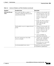
... Catalyst 2900 Series XL and Catalyst 3500 Series XL Software Configuration Guide. • Assess possibility of spectrally incompatible services. Local nonstandard noise source. Excessive interference from other services in bundle. • Consider use of appropriate public profile in bundles shared with 300-ohm microfilters. For more information, refer to a lower profile. Chapter 3 Troubleshooting Diagnosing Problems Table 3-2 Common Problems and Their Solutions (continued) Symptom LRE status LED stays amber...
... Catalyst 2900 Series XL and Catalyst 3500 Series XL Software Configuration Guide. • Assess possibility of spectrally incompatible services. Local nonstandard noise source. Excessive interference from other services in bundle. • Consider use of appropriate public profile in bundles shared with 300-ohm microfilters. For more information, refer to a lower profile. Chapter 3 Troubleshooting Diagnosing Problems Table 3-2 Common Problems and Their Solutions (continued) Symptom LRE status LED stays amber...

Hardware Installation Guide
Page 111
... DTR RTS Connecting to a Terminal Use the thin, flat, RJ-45-to-RJ-45 rollover cable and RJ-45-to-DB-25 female DTE adapter to connect the console port to -DB-25 female DTE adapter is not supplied with the switch. You can order a kit (part number ACS-DSBUASYN=) containing this adapter from Cisco. 78-6461-04 Catalyst 2900 Series XL Hardware Installation Guide B-7 Table B-4 lists the pinouts for the console port, the...
... DTR RTS Connecting to a Terminal Use the thin, flat, RJ-45-to-RJ-45 rollover cable and RJ-45-to-DB-25 female DTE adapter to connect the console port to -DB-25 female DTE adapter is not supplied with the switch. You can order a kit (part number ACS-DSBUASYN=) containing this adapter from Cisco. 78-6461-04 Catalyst 2900 Series XL Hardware Installation Guide B-7 Table B-4 lists the pinouts for the console port, the...


