Software Configuration Guide
Page 7
...Switch-Specific Features in Switch Clusters 6-19 Creating a Switch Cluster 6-19 Enabling a Command Switch 6-19 Adding Member Switches 6-20 Creating a Cluster Standby Group 6-22 Verifying a Switch Cluster 6-24 Using the CLI to Manage Switch Clusters 6-25 Catalyst 1900 and Catalyst 2820 CLI Considerations 6-25 Using SNMP to Manage Switch Clusters 6-26 Administering the Switch... 7-10 Controlling Switch Access with TACACS+ 7-10 Understanding TACACS+ 7-10 TACACS+ Operation 7-12 Configuring TACACS+ 7-12 Default TACACS+ Configuration 7-13 Catalyst 2950 Desktop Switch Software Configuration Guide vii
...Switch-Specific Features in Switch Clusters 6-19 Creating a Switch Cluster 6-19 Enabling a Command Switch 6-19 Adding Member Switches 6-20 Creating a Cluster Standby Group 6-22 Verifying a Switch Cluster 6-24 Using the CLI to Manage Switch Clusters 6-25 Catalyst 1900 and Catalyst 2820 CLI Considerations 6-25 Using SNMP to Manage Switch Clusters 6-26 Administering the Switch... 7-10 Controlling Switch Access with TACACS+ 7-10 Understanding TACACS+ 7-10 TACACS+ Operation 7-12 Configuring TACACS+ 7-12 Default TACACS+ Configuration 7-13 Catalyst 2950 Desktop Switch Software Configuration Guide vii

Software Configuration Guide
Page 14
... STP Port Priorities 14-21 Load Sharing Using STP Path Cost 14-23 Configuring VMPS 14-24 Understanding VMPS 14-25 Dynamic Port VLAN Membership 14-25 VMPS Database Configuration File 14-26 Default VMPS Configuration 14-27 VMPS Configuration Guidelines 14-28 Catalyst 2950 Desktop Switch Software Configuration Guide xiv 78-14982-01
... STP Port Priorities 14-21 Load Sharing Using STP Path Cost 14-23 Configuring VMPS 14-24 Understanding VMPS 14-25 Dynamic Port VLAN Membership 14-25 VMPS Database Configuration File 14-26 Default VMPS Configuration 14-27 VMPS Configuration Guidelines 14-28 Catalyst 2950 Desktop Switch Software Configuration Guide xiv 78-14982-01

Software Configuration Guide
Page 16
Contents 17 C H A P T E R Default Voice VLAN Configuration 16-2 Voice VLAN Configuration Guidelines 16-3 Configuring a Port to Connect to a Cisco 7960 IP Phone 16-3 Configuring Ports to Carry Voice Traffic in 802.1Q Frames 16-4 Configuring Ports to Carry Voice Traffic in 802.1P Priority ...-21 Configuring IGMP Profiles 17-21 Applying IGMP Profiles 17-22 Setting the Maximum Number of IGMP Groups 17-23 Displaying IGMP Filtering Configuration 17-24 Catalyst 2950 Desktop Switch Software Configuration Guide xvi 78-14982-01
Contents 17 C H A P T E R Default Voice VLAN Configuration 16-2 Voice VLAN Configuration Guidelines 16-3 Configuring a Port to Connect to a Cisco 7960 IP Phone 16-3 Configuring Ports to Carry Voice Traffic in 802.1Q Frames 16-4 Configuring Ports to Carry Voice Traffic in 802.1P Priority ...-21 Configuring IGMP Profiles 17-21 Applying IGMP Profiles 17-22 Setting the Maximum Number of IGMP Groups 17-23 Displaying IGMP Filtering Configuration 17-24 Catalyst 2950 Desktop Switch Software Configuration Guide xvi 78-14982-01

Software Configuration Guide
Page 19
... 24-13 SNMP Examples 24-14 Displaying SNMP Status 24-15 Configuring Network Security with ACLs 25-1 Understanding ACLs 25-2 Handling Fragmented and Unfragmented Traffic 25-3 Understanding Access Control Parameters 25-4 Guidelines for Applying ACLs to Physical Interfaces 25-6 Configuring ACLs 25-6 Unsupported Features 25-7 Creating Standard and Extended IP ACLs 25-7 Catalyst 2950 Desktop Switch...
... 24-13 SNMP Examples 24-14 Displaying SNMP Status 24-15 Configuring Network Security with ACLs 25-1 Understanding ACLs 25-2 Handling Fragmented and Unfragmented Traffic 25-3 Understanding Access Control Parameters 25-4 Guidelines for Applying ACLs to Physical Interfaces 25-6 Configuring ACLs 25-6 Unsupported Features 25-7 Creating Standard and Extended IP ACLs 25-7 Catalyst 2950 Desktop Switch...

Software Configuration Guide
Page 21
... 26-16 Classifying Traffic by Using Class Maps 26-20 Classifying, Policing, and Marking Traffic by Using Policy Maps 26-21 Configuring CoS Maps 26-24 Configuring the CoS-to-DSCP Map 26-25 Configuring the DSCP-to-CoS Map 26-26 Configuring CoS and WRR 26-27 Configuring CoS Priority...-11 Troubleshooting 28-1 LRE Statistics 28-1 Using Recovery Procedures 28-6 Recovering from Corrupted Software 28-6 Recovering from a Lost or Forgotten Password 28-6 Recovering from a Command Switch Failure 28-8 Catalyst 2950 Desktop Switch Software Configuration Guide xxi
... 26-16 Classifying Traffic by Using Class Maps 26-20 Classifying, Policing, and Marking Traffic by Using Policy Maps 26-21 Configuring CoS Maps 26-24 Configuring the CoS-to-DSCP Map 26-25 Configuring the DSCP-to-CoS Map 26-26 Configuring CoS and WRR 26-27 Configuring CoS Priority...-11 Troubleshooting 28-1 LRE Statistics 28-1 Using Recovery Procedures 28-6 Recovering from Corrupted Software 28-6 Recovering from a Lost or Forgotten Password 28-6 Recovering from a Command Switch Failure 28-8 Catalyst 2950 Desktop Switch Software Configuration Guide xxi

Software Configuration Guide
Page 23
... Deleting a Stored Configuration File B-20 Working with Software Images B-20 Image Location on the Switch B-20 tar File Format of Images on a Server or Cisco.com B-21 Copying Image Files By Using TFTP B-22 Preparing to Download or Upload an ...Image File By Using TFTP B-22 Downloading an Image File By Using TFTP B-23 Uploading an Image File By Using TFTP B-24 Copying Image...Using RCP B-30 Uploading an Image File By Using RCP B-32 78-14982-01 Catalyst 2950 Desktop Switch Software Configuration Guide xxiii
... Deleting a Stored Configuration File B-20 Working with Software Images B-20 Image Location on the Switch B-20 tar File Format of Images on a Server or Cisco.com B-21 Copying Image Files By Using TFTP B-22 Preparing to Download or Upload an ...Image File By Using TFTP B-22 Downloading an Image File By Using TFTP B-23 Uploading an Image File By Using TFTP B-24 Copying Image...Using RCP B-30 Uploading an Image File By Using RCP B-32 78-14982-01 Catalyst 2950 Desktop Switch Software Configuration Guide xxiii
Software Configuration Guide
Page 27
...(VTP) VLAN database for all the traffic flowing among switches on the switch for configuring physical interfaces. Catalyst 2950 Desktop Switch Software Configuration Guide xxvii Chapter 10, "Configuring LRE," describes...messages. Chapter 12, "Configuring RSTP and MSTP," describes how to configure Cisco Discovery Protocol (CDP) on your switch is running the per-VLAN spanning-tree (PVST) or the MSTP. Chapter... Network Management Protocol (SNMP). Chapter 24, "Configuring SNMP," describes how to configure Switched Port Analyzer (SPAN) and Remote SPAN (RSPAN), which is used through SNMP...
...(VTP) VLAN database for all the traffic flowing among switches on the switch for configuring physical interfaces. Catalyst 2950 Desktop Switch Software Configuration Guide xxvii Chapter 10, "Configuring LRE," describes...messages. Chapter 12, "Configuring RSTP and MSTP," describes how to configure Cisco Discovery Protocol (CDP) on your switch is running the per-VLAN spanning-tree (PVST) or the MSTP. Chapter... Network Management Protocol (SNMP). Chapter 24, "Configuring SNMP," describes how to configure Switched Port Analyzer (SPAN) and Remote SPAN (RSPAN), which is used through SNMP...
Software Configuration Guide
Page 33
... Switch Catalyst 2950-12 Software Image SI1 Catalyst 2950-24 SI Catalyst 2950C-24 EI2 Catalyst 2950G-12-EI EI Catalyst 2950G-24-EI EI Catalyst 2950G-24-EI-DC EI Catalyst 2950G-48-EI EI Catalyst 2950SX-24 SI Catalyst 2950T-24 EI Catalyst 2950ST-24-LRE YJ3 Catalyst 2950ST-8-LRE YJ 1. EI = enhanced software image 3. YJ = enhanced software image for LRE switches Note The SI and EI images are for LRE switches. 78-14982-01 Catalyst 2950...
... Switch Catalyst 2950-12 Software Image SI1 Catalyst 2950-24 SI Catalyst 2950C-24 EI2 Catalyst 2950G-12-EI EI Catalyst 2950G-24-EI EI Catalyst 2950G-24-EI-DC EI Catalyst 2950G-48-EI EI Catalyst 2950SX-24 SI Catalyst 2950T-24 EI Catalyst 2950ST-24-LRE YJ3 Catalyst 2950ST-8-LRE YJ 1. EI = enhanced software image 3. YJ = enhanced software image for LRE switches Note The SI and EI images are for LRE switches. 78-14982-01 Catalyst 2950...
Software Configuration Guide
Page 35
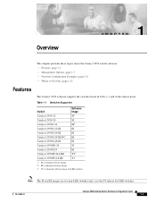
The Catalyst 2950G-12-EI, 2950G-24-EI, 2950G-24-EI-DC, and 2950G-48-EI switches running Cisco IOS Release 12.1(6)EA2 or later support frame sizes from 1500 to 1530 bytes • Per-port broadcast storm control ... not directly connected to the release notes for a list of bandwidth between switches, routers, and servers • Support for command-switch redundancy. Chapter 1 Overview Features • Switch clustering technology used for this switch. 78-14982-01 Catalyst 2950 Desktop Switch Software Configuration Guide 1-3 Extended discovery of up to the release notes for ...
The Catalyst 2950G-12-EI, 2950G-24-EI, 2950G-24-EI-DC, and 2950G-48-EI switches running Cisco IOS Release 12.1(6)EA2 or later support frame sizes from 1500 to 1530 bytes • Per-port broadcast storm control ... not directly connected to the release notes for a list of bandwidth between switches, routers, and servers • Support for command-switch redundancy. Chapter 1 Overview Features • Switch clustering technology used for this switch. 78-14982-01 Catalyst 2950 Desktop Switch Software Configuration Guide 1-3 Extended discovery of up to the release notes for ...
Software Configuration Guide
Page 37
...security policies (available only with appropriate network resources, traffic patterns, and bandwidth Note The Catalyst 2950-12, Catalyst 2950-24, and Catalyst 2950SX-24 switches support only 64 port-based VLANs. • The switch supports up to set the aging time for secure addresses on all ports for network... moves, adds, and changes; Loop guard for preventing alternate or root ports from Cisco IP Phones...
...security policies (available only with appropriate network resources, traffic patterns, and bandwidth Note The Catalyst 2950-12, Catalyst 2950-24, and Catalyst 2950SX-24 switches support only 64 port-based VLANs. • The switch supports up to set the aging time for secure addresses on all ports for network... moves, adds, and changes; Loop guard for preventing alternate or root ports from Cisco IP Phones...
Software Configuration Guide
Page 39
... and display switch images to the other devices in your network. 78-14982-01 Catalyst 2950 Desktop Switch Software Configuration Guide 1-7 You can use and makes switch and switch cluster management accessible to the switch, executing the...Chapter 2, "Using the Command-Line Interface." • IE2100-Cisco Intelligence Engine 2100 Series Configuration Registrar is enhanced to 16 interconnected and supported Catalyst switches through its various management interfaces. For more information about the CLI...more information about IE2100, see the Chapter 24, "Configuring SNMP."
... and display switch images to the other devices in your network. 78-14982-01 Catalyst 2950 Desktop Switch Software Configuration Guide 1-7 You can use and makes switch and switch cluster management accessible to the switch, executing the...Chapter 2, "Using the Command-Line Interface." • IE2100-Cisco Intelligence Engine 2100 Series Configuration Registrar is enhanced to 16 interconnected and supported Catalyst switches through its various management interfaces. For more information about the CLI...more information about IE2100, see the Chapter 24, "Configuring SNMP."
Software Configuration Guide
Page 71
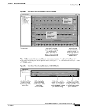
...to change port-related settings. Figure 3-4 Front Panel View from a Standalone 2950 LRE Switch 2950-24 2950-24 86459 Left-click the Mode button to select multiple ports. The color of the switch and connected RPS. Right-click the command switch image to display the cluster pop-up menu, and select an option to... view or change the meaning of the port LEDs. LEDs display the current port mode and the status of the port LED reflects port or link status. 78-14982-01 Catalyst 2950 Desktop Switch ...
...to change port-related settings. Figure 3-4 Front Panel View from a Standalone 2950 LRE Switch 2950-24 2950-24 86459 Left-click the Mode button to select multiple ports. The color of the switch and connected RPS. Right-click the command switch image to display the cluster pop-up menu, and select an option to... view or change the meaning of the port LEDs. LEDs display the current port mode and the status of the port LED reflects port or link status. 78-14982-01 Catalyst 2950 Desktop Switch ...
Software Configuration Guide
Page 72
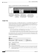
... corresponding front-panel image. Catalyst 2950 Desktop Switch Software Configuration Guide 3-6 78-14982-01 The sequence of the switch is not operating, or the switch is operating normally. Figure 3-6 Cluster-Tree Icons Table 3-1 Cluster Tree Icon Colors Color Green Yellow Red Device Status Switch is receiving power from a 2950 non-LRE Standalone Switch 2950-24 2950-24 Left-click the Mode LEDs...
... corresponding front-panel image. Catalyst 2950 Desktop Switch Software Configuration Guide 3-6 78-14982-01 The sequence of the switch is not operating, or the switch is operating normally. Figure 3-6 Cluster-Tree Icons Table 3-1 Cluster Tree Icon Colors Color Green Yellow Red Device Status Switch is receiving power from a 2950 non-LRE Standalone Switch 2950-24 2950-24 Left-click the Mode LEDs...

Software Configuration Guide
Page 90
... read -write access modes, see the "Access Modes in CMS" section on page 3-31. 2. Change the host name of a Command-Switch Icon Popup Menu Option Task Collapse cluster Host Name1 View the neighborhood outside a specific cluster. Not available in read -write access modes, see... information about the device. 1. Bandwidth Graphs Display graphs that plot the total bandwidth in CMS" section on page 3-31. 3-24 Catalyst 2950 Desktop Switch Software Configuration Guide 78-14982-01 Properties Display information about the read-only and read -only mode. Launch Device Manager for...
... read -write access modes, see the "Access Modes in CMS" section on page 3-31. 2. Change the host name of a Command-Switch Icon Popup Menu Option Task Collapse cluster Host Name1 View the neighborhood outside a specific cluster. Not available in read -write access modes, see... information about the device. 1. Bandwidth Graphs Display graphs that plot the total bandwidth in CMS" section on page 3-31. 3-24 Catalyst 2950 Desktop Switch Software Configuration Guide 78-14982-01 Properties Display information about the read-only and read -only mode. Launch Device Manager for...

Software Configuration Guide
Page 108
...Switch 1 Switch 2 Switch 3 Switch 4 00e0.9f1e.2001 00e0.9f1e.2002 00e0.9f1e.2003 00e0.9f1e.2004 Cisco router 10.0.0.10 10.0.0.1 10.0.0.2 10.0.0.3 49066 DHCP server DNS server TFTP server (maritsu) Table 4-2 shows the configuration of the reserved leases on the DHCP server. Assigning Switch Information Chapter 4 Assigning the Switch... 10.0.0.2 maritsu or 10.0.0.3 switch3-confg switch3 Switch-4 00e0.9f1e.2004 10.0.0.24 255.255.255.0 10.0.0.10 10.0.0.2 maritsu or 10.0.0.3 switch4-confg switch4 Catalyst 2950 Desktop Switch Software Configuration Guide 4-8 78-14982-01 Example ...
...Switch 1 Switch 2 Switch 3 Switch 4 00e0.9f1e.2001 00e0.9f1e.2002 00e0.9f1e.2003 00e0.9f1e.2004 Cisco router 10.0.0.10 10.0.0.1 10.0.0.2 10.0.0.3 49066 DHCP server DNS server TFTP server (maritsu) Table 4-2 shows the configuration of the reserved leases on the DHCP server. Assigning Switch Information Chapter 4 Assigning the Switch... 10.0.0.2 maritsu or 10.0.0.3 switch3-confg switch3 Switch-4 00e0.9f1e.2004 10.0.0.24 255.255.255.0 10.0.0.10 10.0.0.2 maritsu or 10.0.0.3 switch4-confg switch4 Catalyst 2950 Desktop Switch Software Configuration Guide 4-8 78-14982-01 Example ...

Software Configuration Guide
Page 109
... contains the network-confg file used in the same way. 78-14982-01 Catalyst 2950 Desktop Switch Software Configuration Guide 4-9 TFTP Server Configuration (on UNIX) The TFTP server base directory is given in the DHCP server reply, Switch 1 reads the network-confg file from the base directory of the TFTP server... prompt> cat network-confg ip host switch1 10.0.0.21 ip host switch2 10.0.0.22 ip host switch3 10.0.0.23 ip host switch4 10.0.0.24 DHCP Client Configuration No configuration file is present on its configuration file as shown in this display: prompt> cd /tftpserver/work /. ...
... contains the network-confg file used in the same way. 78-14982-01 Catalyst 2950 Desktop Switch Software Configuration Guide 4-9 TFTP Server Configuration (on UNIX) The TFTP server base directory is given in the DHCP server reply, Switch 1 reads the network-confg file from the base directory of the TFTP server... prompt> cat network-confg ip host switch1 10.0.0.21 ip host switch2 10.0.0.22 ip host switch3 10.0.0.23 ip host switch4 10.0.0.24 DHCP Client Configuration No configuration file is present on its configuration file as shown in this display: prompt> cd /tftpserver/work /. ...

Software Configuration Guide
Page 142
...24, "Configuring SNMP." For password considerations specific to the Catalyst 1900 and Catalyst 2820 switches, refer to Your Switch" section on page 7-1. For SNMP considerations specific to the Catalyst 1900 and Catalyst 2820 switches, refer to the installation and configuration guides specific to identify the switch... Planning a Switch Cluster Chapter 6 Clustering Switches Host Names You do not need to assign a host name to either a command switch or an eligible cluster member. The default host name for those switches. 6-16 Catalyst 2950 Desktop Switch Software Configuration ...
...24, "Configuring SNMP." For password considerations specific to the Catalyst 1900 and Catalyst 2820 switches, refer to Your Switch" section on page 7-1. For SNMP considerations specific to the Catalyst 1900 and Catalyst 2820 switches, refer to the installation and configuration guides specific to identify the switch... Planning a Switch Cluster Chapter 6 Clustering Switches Host Names You do not need to assign a host name to either a command switch or an eligible cluster member. The default host name for those switches. 6-16 Catalyst 2950 Desktop Switch Software Configuration ...

Software Configuration Guide
Page 145
... using the CLI commands. Creating a Switch Cluster Using CMS to a member switch are available from the switch cluster. If your switch cluster has Catalyst 2900 XL, Catalyst 2950, and Catalyst 3500 XL switches, the Catalyst 2950 should be the command switch: - Chapter 6 Clustering Switches Creating a Switch Cluster Availability of Catalyst switches eligible for switch clustering, including which ones can be command switches and which ones can enable a command...
... using the CLI commands. Creating a Switch Cluster Using CMS to a member switch are available from the switch cluster. If your switch cluster has Catalyst 2900 XL, Catalyst 2950, and Catalyst 3500 XL switches, the Catalyst 2950 should be the command switch: - Chapter 6 Clustering Switches Creating a Switch Cluster Availability of Catalyst switches eligible for switch clustering, including which ones can be command switches and which ones can enable a command...

Software Configuration Guide
Page 147
...24-1 Select a switch, and click Add. Figure 6-11 Add to select more information about setting passwords, see the "TACACS+ and RADIUS" section on page 6-16. If no password exists for the switch, leave this field blank. 65724 78-14982-01 Catalyst 2950 Desktop Switch... Software Configuration Guide 6-21 For more than one switch. Chapter 6 Clustering Switches Creating a Switch Cluster If a candidate switch in switch clusters, see the "Passwords" section on page...
...24-1 Select a switch, and click Add. Figure 6-11 Add to select more information about setting passwords, see the "TACACS+ and RADIUS" section on page 6-16. If no password exists for the switch, leave this field blank. 65724 78-14982-01 Catalyst 2950 Desktop Switch... Software Configuration Guide 6-21 For more than one switch. Chapter 6 Clustering Switches Creating a Switch Cluster If a candidate switch in switch clusters, see the "Passwords" section on page...

Software Configuration Guide
Page 149
...information about the standby hold time and hello time intervals, refer to the Cisco IOS Release 12.1 documentation set by using the CLI. Figure 6-13 Standby Command Configuration Window 3550C (cisco WS-C3550-C-24, HC, ... The Standby Command Configuration window uses the default values for ... have the preempt command enabled. The group name can be changed. 65726 78-14982-01 Catalyst 2950 Desktop Switch Software Configuration Guide 6-23 NMS-3550-12T-149 (cisco WS-C3550-1 3550-150 (cisco WS-C3550-12T, SC, ... The default HSRP standby hello time interval is 0. Chapter ...
...information about the standby hold time and hello time intervals, refer to the Cisco IOS Release 12.1 documentation set by using the CLI. Figure 6-13 Standby Command Configuration Window 3550C (cisco WS-C3550-C-24, HC, ... The Standby Command Configuration window uses the default values for ... have the preempt command enabled. The group name can be changed. 65726 78-14982-01 Catalyst 2950 Desktop Switch Software Configuration Guide 6-23 NMS-3550-12T-149 (cisco WS-C3550-1 3550-150 (cisco WS-C3550-12T, SC, ... The default HSRP standby hello time interval is 0. Chapter ...
