
Hardware Installation Guide
Page 4
Contents 2 C H A P T E R Rear-Panel Description 1-21 Power Connectors 1-22 Internal Power Supply Connector 1-22 DC Power Connector 1-23 Cisco RPS Connector 1-23 Console Port 1-24 Management Options 1-24 Installation 2-1 Preparing for Installation 2-1 Warnings 2-1 Installation Guidelines 2-4 Verifying Package Contents 2-5 Verifying Switch Operation 2-6 Installing the Switch 2-7 Installing the Switch in a Rack 2-7 Attaching the Brackets to the Switch 2-8 Mounting the Switch in a Rack 2-16 Attaching the...
Contents 2 C H A P T E R Rear-Panel Description 1-21 Power Connectors 1-22 Internal Power Supply Connector 1-22 DC Power Connector 1-23 Cisco RPS Connector 1-23 Console Port 1-24 Management Options 1-24 Installation 2-1 Preparing for Installation 2-1 Warnings 2-1 Installation Guidelines 2-4 Verifying Package Contents 2-5 Verifying Switch Operation 2-6 Installing the Switch 2-7 Installing the Switch in a Rack 2-7 Attaching the Brackets to the Switch 2-8 Mounting the Switch in a Rack 2-16 Attaching the...

Hardware Installation Guide
Page 6
... P P E N D I X D A P P E N D I X INDEX Connecting to DC Power C-1 Preparing for Installation C-2 Grounding the Switch C-2 Wiring the DC-Input Power Source C-4 Configuring the Switch with the CLI-Based Setup Program D-1 Accessing the CLI D-1 Accessing the CLI Through Express Setup D-1 Accessing the ... Out What You Need D-3 Connecting to the Console Port D-3 Starting the Terminal-Emulation Software D-4 Connecting to a Power Source D-5 Entering the Initial Configuration Information D-5 IP Settings D-5 Completing the Setup Program D-6 Catalyst 2950 Switch Hardware Installation Guide vi OL-6156-01
... P P E N D I X D A P P E N D I X INDEX Connecting to DC Power C-1 Preparing for Installation C-2 Grounding the Switch C-2 Wiring the DC-Input Power Source C-4 Configuring the Switch with the CLI-Based Setup Program D-1 Accessing the CLI D-1 Accessing the CLI Through Express Setup D-1 Accessing the ... Out What You Need D-3 Connecting to the Console Port D-3 Starting the Terminal-Emulation Software D-4 Connecting to a Power Source D-5 Entering the Initial Configuration Information D-5 IP Settings D-5 Completing the Setup Program D-6 Catalyst 2950 Switch Hardware Installation Guide vi OL-6156-01

Hardware Installation Guide
Page 8
... as long as its service center will use the product, provided that the fan and power supply warranty is limited to five (5) years. If you purchased the product. In the event of a discontinuance of product manufacture, the Cisco warranty support is limited to ship a replacement part within ten (10) working days after... (RMA) Number Contact the company from whom you purchased the product directly from Company telephone number Product model number Product serial number Maintenance contract number Catalyst 2950 Switch Hardware Installation Guide viii OL-6156-01
... as long as its service center will use the product, provided that the fan and power supply warranty is limited to five (5) years. If you purchased the product. In the event of a discontinuance of product manufacture, the Cisco warranty support is limited to ship a replacement part within ten (10) working days after... (RMA) Number Contact the company from whom you purchased the product directly from Company telephone number Product model number Product serial number Maintenance contract number Catalyst 2950 Switch Hardware Installation Guide viii OL-6156-01
Hardware Installation Guide
Page 16
...-7814233=) For information about the Catalyst 2950 Long-Reach Ethernet (LRE) switches, see these documents: • Catalyst 2950 Switch Software Configuration Guide (order number DOC-7814982=) • Catalyst 2950 Switch Command Reference (order number DOC-7814984=) • Catalyst 2950 Switch System Message Guide (order number DOC-7814981=) • Release Notes for the Catalyst 2950 LRE Switch (not orderable but available on Cisco.com) For other information...
...-7814233=) For information about the Catalyst 2950 Long-Reach Ethernet (LRE) switches, see these documents: • Catalyst 2950 Switch Software Configuration Guide (order number DOC-7814982=) • Catalyst 2950 Switch Command Reference (order number DOC-7814984=) • Catalyst 2950 Switch System Message Guide (order number DOC-7814981=) • Release Notes for the Catalyst 2950 LRE Switch (not orderable but available on Cisco.com) For other information...
Hardware Installation Guide
Page 21
...-6156-01 Catalyst 2950 Switch Hardware Installation Guide 1-1 All models of Ethernet switches that show the Catalyst 2950 switches. Catalyst 2950-12 switch-12 10/100 Ethernet ports - Figure 1-1 through Figure 1-12 show how you can be deployed as servers, routers, and other switches and network devices. Catalyst 2950-24 switch-24 10/100 Ethernet ports - and DC-powered switches, and troubleshooting help. Features The Catalyst 2950 switches are switch management options...
...-6156-01 Catalyst 2950 Switch Hardware Installation Guide 1-1 All models of Ethernet switches that show the Catalyst 2950 switches. Catalyst 2950-12 switch-12 10/100 Ethernet ports - Figure 1-1 through Figure 1-12 show how you can be deployed as servers, routers, and other switches and network devices. Catalyst 2950-24 switch-24 10/100 Ethernet ports - and DC-powered switches, and troubleshooting help. Features The Catalyst 2950 switches are switch management options...

Hardware Installation Guide
Page 22
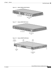
..., and then forwards the packet to the destination port Catalyst 2950 Switch Hardware Installation Guide 1-2 OL-6156-01 For 100BASE-FX ports, supports only 100-Mbps and full-duplex settings - Catalyst 2950G-24-EI-DC-24 10/100 Ethernet ports and 2 GBIC module slots with DC-input power. (Two of the four uplink ports are active at...
..., and then forwards the packet to the destination port Catalyst 2950 Switch Hardware Installation Guide 1-2 OL-6156-01 For 100BASE-FX ports, supports only 100-Mbps and full-duplex settings - Catalyst 2950G-24-EI-DC-24 10/100 Ethernet ports and 2 GBIC module slots with DC-input power. (Two of the four uplink ports are active at...

Hardware Installation Guide
Page 23
... button. On the Catalyst 2950ST-24 LRE 997 switch, the front panel contains a DC power connector (also referred to Figure 1-12 show the switches. In Table 1-1, Yes means that the CPE is supported by certain Catalyst 2950 LRE switches. No means that the CPE is not supported by the switch. Connection for an optional Cisco RPS 300 redundant power system (RPS...
... button. On the Catalyst 2950ST-24 LRE 997 switch, the front panel contains a DC power connector (also referred to Figure 1-12 show the switches. In Table 1-1, Yes means that the CPE is supported by certain Catalyst 2950 LRE switches. No means that the CPE is not supported by the switch. Connection for an optional Cisco RPS 300 redundant power system (RPS...
Hardware Installation Guide
Page 25
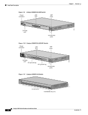
...22 23 24 25 26 27 28 29 30 31 32 16X 18X 33 31X 33X 34 35 36 37 38 39 40 41 42 43 44 45 46 47 48 47X 32X 34X 48X 10/100 ports Catalyst 2950 SERIES 1 2 GBIC module slots Figure 1-8 Catalyst 2950ST-8 LRE Switch Power LRE connector... port SFP ports 110.00A-1/02R.75A/TA2I0N500G--26400HVZ~ MODE SYST RPS STAT SPEED CONSOLE 1 2 3 4 5 6 7 8 Console port Catalyst 2950 LRE SERIES 1 2 1 2 10/100/1000 ports 60977 ...
...22 23 24 25 26 27 28 29 30 31 32 16X 18X 33 31X 33X 34 35 36 37 38 39 40 41 42 43 44 45 46 47 48 47X 32X 34X 48X 10/100 ports Catalyst 2950 SERIES 1 2 GBIC module slots Figure 1-8 Catalyst 2950ST-8 LRE Switch Power LRE connector... port SFP ports 110.00A-1/02R.75A/TA2I0N500G--26400HVZ~ MODE SYST RPS STAT SPEED CONSOLE 1 2 3 4 5 6 7 8 Console port Catalyst 2950 LRE SERIES 1 2 1 2 10/100/1000 ports 60977 ...
Hardware Installation Guide
Page 26
... Description Figure 1-9 Catalyst 2950ST-24 LRE Switch Power LRE connector port SFP ports 110.00A-1/02R.75A/TA2I0N500G--26400HVZ~ MODE SYST RPS STAT SPEED CONSOLE 1 2 3 4 5 6 7 8 9 10 11 12 Console port 13 14 15 16 17 18 19 20 21 22 23 24 Catalyst 2950 SERIES LRE 1 2 1 2 10/100/1000 ports Figure 1-10 Catalyst 2950ST-24 LRE 997 Switch Power connector LRE...
... Description Figure 1-9 Catalyst 2950ST-24 LRE Switch Power LRE connector port SFP ports 110.00A-1/02R.75A/TA2I0N500G--26400HVZ~ MODE SYST RPS STAT SPEED CONSOLE 1 2 3 4 5 6 7 8 9 10 11 12 Console port 13 14 15 16 17 18 19 20 21 22 23 24 Catalyst 2950 SERIES LRE 1 2 1 2 10/100/1000 ports Figure 1-10 Catalyst 2950ST-24 LRE 997 Switch Power connector LRE...
Hardware Installation Guide
Page 29
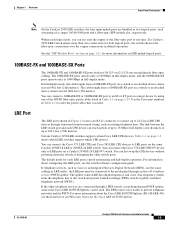
... must be used. If a Catalyst 2950 LRE switch senses more information on a target device by using one of the MT-RJ fiber-optic patch cables listed in full-duplex mode, and the 1000BASE-SX ports operate only at one RJ-21 connector to connect up to 24 Cisco LRE CPE devices through a plain...- LRE Port The LRE port (shown in full-duplex mode. The link between the LRE switch port and each logical port, you need. You can hot swap the CPE devices without powering down the switch or disrupting the other telephone services are bundled as two logical ports, each consisting of up...
... must be used. If a Catalyst 2950 LRE switch senses more information on a target device by using one of the MT-RJ fiber-optic patch cables listed in full-duplex mode, and the 1000BASE-SX ports operate only at one RJ-21 connector to connect up to 24 Cisco LRE CPE devices through a plain...- LRE Port The LRE port (shown in full-duplex mode. The link between the LRE switch port and each logical port, you need. You can hot swap the CPE devices without powering down the switch or disrupting the other telephone services are bundled as two logical ports, each consisting of up...

Hardware Installation Guide
Page 35
... CONSOLE STAT LED Speed Mode LED button 1 2 3 4 5 6 7 8 9 10 11 12 89364 OL-6156-01 Catalyst 2950 Switch Hardware Installation Guide 1-15 Chapter 1 Overview Front-Panel Description Figure 1-18 LEDs on Catalyst 2950ST-8 LRE and 2950ST-24 LRE Switches System LED Redundant power system LED Port status LEDs 81187 110.00A-1/02R.75A/TA2I0N500G--26400HVZ~ MODE SYST RPS...
... CONSOLE STAT LED Speed Mode LED button 1 2 3 4 5 6 7 8 9 10 11 12 89364 OL-6156-01 Catalyst 2950 Switch Hardware Installation Guide 1-15 Chapter 1 Overview Front-Panel Description Figure 1-18 LEDs on Catalyst 2950ST-8 LRE and 2950ST-24 LRE Switches System LED Redundant power system LED Port status LEDs 81187 110.00A-1/02R.75A/TA2I0N500G--26400HVZ~ MODE SYST RPS...

Hardware Installation Guide
Page 36
... type of information displayed. 1-16 Catalyst 2950 Switch Hardware Installation Guide OL-6156-01 Table 1-3 lists the LED colors and meanings. Table 1-4 RPS LED Color RPS Status Off RPS is off or is receiving power and functioning properly. For information about the Cisco RPS 300, see the Cisco RPS 300 Redundant Power System Hardware Installation Guide. For...
... type of information displayed. 1-16 Catalyst 2950 Switch Hardware Installation Guide OL-6156-01 Table 1-3 lists the LED colors and meanings. Table 1-4 RPS LED Color RPS Status Off RPS is off or is receiving power and functioning properly. For information about the Cisco RPS 300, see the Cisco RPS 300 Redundant Power System Hardware Installation Guide. For...

Hardware Installation Guide
Page 37
...24 for details. UTIL (utilization) Green The current backplane utilization that is operating in use by management, an address violation, or Spanning Tree Protocol (STP). Green and amber See Figure 1-20 to interpret these colors for the LRE switches... The maximum backplane utilization since the switch was disabled by the switch. Solid green Link present. Port was powered on a logarithmic scale. DUPLX Off...is set to interpret the colors for the non-LRE switches. The bandwidth in full duplex. A Catalyst 2950 LRE switch does not have a UTIL or a DUPLX LED. Flashing...
...24 for details. UTIL (utilization) Green The current backplane utilization that is operating in use by management, an address violation, or Spanning Tree Protocol (STP). Green and amber See Figure 1-20 to interpret these colors for the LRE switches... The maximum backplane utilization since the switch was disabled by the switch. Solid green Link present. Port was powered on a logarithmic scale. DUPLX Off...is set to interpret the colors for the non-LRE switches. The bandwidth in full duplex. A Catalyst 2950 LRE switch does not have a UTIL or a DUPLX LED. Flashing...

Hardware Installation Guide
Page 41
... SPEED 2X MODE 16X 18X 32X 34X 2 48X < 25% + 25% - 49% + 50% + Rear-Panel Description Other than the Catalyst 2950G-24-EI-DC switch and the Catalyst 2950 LRE switches, the rear panel of a Catalyst 2950 switch has an AC power connector, an RPS connector, and an RJ-45 console port. (See Figure 1-25 and Figure 1-26.) The rear panel...
... SPEED 2X MODE 16X 18X 32X 34X 2 48X < 25% + 25% - 49% + 50% + Rear-Panel Description Other than the Catalyst 2950G-24-EI-DC switch and the Catalyst 2950 LRE switches, the rear panel of a Catalyst 2950 switch has an AC power connector, an RPS connector, and an RJ-45 console port. (See Figure 1-25 and Figure 1-26.) The rear panel...

Hardware Installation Guide
Page 42
...-8 LRE Switch, Catalyst 2950ST-24 LRE, and Catalyst 2950ST-24 LRE 997 Switch Rear Panel RPS Fans connector 81225 Power Connectors You can order these L-shaped AC power cords from your Cisco sales representative: • CAB-NP1200-AC-AR= • CAB-NP1200-AC-AU= • CAB-NP1200-AC-CH= • CAB-NP1200-AC-EU= 1-22 Catalyst 2950 Switch Hardware Installation Guide OL...
...-8 LRE Switch, Catalyst 2950ST-24 LRE, and Catalyst 2950ST-24 LRE 997 Switch Rear Panel RPS Fans connector 81225 Power Connectors You can order these L-shaped AC power cords from your Cisco sales representative: • CAB-NP1200-AC-AR= • CAB-NP1200-AC-AU= • CAB-NP1200-AC-CH= • CAB-NP1200-AC-EU= 1-22 Catalyst 2950 Switch Hardware Installation Guide OL...

Hardware Installation Guide
Page 43
... to the RPS receptacle. It automatically senses when the internal power supply of a connected device fails and provides power to one failed device at a time. For more information, see the Cisco RPS 675 documentation. OL-6156-01 Catalyst 2950 Switch Hardware Installation Guide 1-23 It has dual feeds (A and ...external network devices and provides DC power to that device, preventing loss of 675 W. Caution You must connect the Catalyst 2950G-24-EI-DC and 2950ST-24 LRE 997 switches only to a DC-input power source that are diode-OR-ed into a single power block. Use the supplied RPS ...
... to the RPS receptacle. It automatically senses when the internal power supply of a connected device fails and provides power to one failed device at a time. For more information, see the Cisco RPS 675 documentation. OL-6156-01 Catalyst 2950 Switch Hardware Installation Guide 1-23 It has dual feeds (A and ...external network devices and provides DC power to that device, preventing loss of 675 W. Caution You must connect the Catalyst 2950G-24-EI-DC and 2950ST-24 LRE 997 switches only to a DC-input power source that are diode-OR-ed into a single power block. Use the supplied RPS ...

Hardware Installation Guide
Page 47
... Installation Guide 2-1 Read these warnings in this order: • Preparing for the Catalyst 2950 Switch. Warning Attach only the Cisco Redundant Power Supply (RPS) (model PWR300-AC-RPS-N1) to Go Next, page 2-40 Preparing for Installation This section provides information about these topics: • Warnings, page 2-1 &#... Ports, page 2-35 • Connecting to SFP Modules, page 2-38 • Where to the RPS receptacle. Installation CH A P T E R 2 This chapter describes how to install your switch, interpret the power-on self-test (POST), and connect the...
... Installation Guide 2-1 Read these warnings in this order: • Preparing for the Catalyst 2950 Switch. Warning Attach only the Cisco Redundant Power Supply (RPS) (model PWR300-AC-RPS-N1) to Go Next, page 2-40 Preparing for Installation This section provides information about these topics: • Warnings, page 2-1 &#... Ports, page 2-35 • Connecting to SFP Modules, page 2-38 • Where to the RPS receptacle. Installation CH A P T E R 2 This chapter describes how to install your switch, interpret the power-on self-test (POST), and connect the...

Hardware Installation Guide
Page 48
...temperature of 113°F (45°C). Statement 1006 Warning To prevent the switch from the bottom to the power source. To prevent airflow restriction, allow at all national laws and regulations. Statement 42 Catalyst 2950 Switch Hardware Installation Guide 2-2 OL-6156-01 Statement 1001 Warning Read the installation ..., load the rack from overheating, do not operate it last. Preparing for Installation Chapter 2 Installation Warning Attach only the Cisco RPS (model PWR675-AC-RPS-N1) to earth ground during periods of the rack if it serves as the main disconnecting device.
...temperature of 113°F (45°C). Statement 1006 Warning To prevent the switch from the bottom to the power source. To prevent airflow restriction, allow at all national laws and regulations. Statement 42 Catalyst 2950 Switch Hardware Installation Guide 2-2 OL-6156-01 Statement 1001 Warning Read the installation ..., load the rack from overheating, do not operate it last. Preparing for Installation Chapter 2 Installation Warning Attach only the Cisco RPS (model PWR675-AC-RPS-N1) to earth ground during periods of the rack if it serves as the main disconnecting device.

Hardware Installation Guide
Page 49
... or view directly with the front panel facing up when connected to power and ground and can cause severe bodily injury and equipment damage. Statement 121C Warning The Catalyst 2950ST-24 LRE 997 contains no field-replaceable units (FRUs). Metal objects will heat... Warning The Catalyst 2950G-24-EI-DC contains no field-replaceable units (FRUs). Statement 121D OL-6156-01 Catalyst 2950 Switch Hardware Installation Guide 2-3 Chapter 2 Installation Preparing for this unit, contact your reseller or Cisco sales representative. Ensure that is connected to the switch, install an...
... or view directly with the front panel facing up when connected to power and ground and can cause severe bodily injury and equipment damage. Statement 121C Warning The Catalyst 2950ST-24 LRE 997 contains no field-replaceable units (FRUs). Metal objects will heat... Warning The Catalyst 2950G-24-EI-DC contains no field-replaceable units (FRUs). Statement 121D OL-6156-01 Catalyst 2950 Switch Hardware Installation Guide 2-3 Chapter 2 Installation Preparing for this unit, contact your reseller or Cisco sales representative. Ensure that is connected to the switch, install an...

Hardware Installation Guide
Page 50
... (CWDM) GBIC module ports, the cable length from the DC circuit. For specific cable lengths, see the CWDM GBIC module documentation. Catalyst 2950 Switch Hardware Installation Guide 2-4 OL-6156-01 Statement 196 Warning An exposed wire lead from the terminal block plug. A restricted access area can...of a special tool, lock and key, or other means of electricity. Use a voltmeter to test for 0 (zero) voltage at the power terminals on and running POST. Preparing for Installation Chapter 2 Installation Warning This unit is to be installed and maintained by service personnel only ...
... (CWDM) GBIC module ports, the cable length from the DC circuit. For specific cable lengths, see the CWDM GBIC module documentation. Catalyst 2950 Switch Hardware Installation Guide 2-4 OL-6156-01 Statement 196 Warning An exposed wire lead from the terminal block plug. A restricted access area can...of a special tool, lock and key, or other means of electricity. Use a voltmeter to test for 0 (zero) voltage at the power terminals on and running POST. Preparing for Installation Chapter 2 Installation Warning This unit is to be installed and maintained by service personnel only ...
