

Configuration Guide
Page 53
..., toolbar, and the Front-Panel and Topology view popup menus. The menu bar of an option based on your switch cluster has Catalyst 2900 XL, Catalyst 2950, and Catalyst 3500 XL switches, the Catalyst 2950 should be part of all Layer 2 switches in CMS: read-only (access level 1-14) and read-write (access level 15). Chapter 2 Getting Started with CMS...
..., toolbar, and the Front-Panel and Topology view popup menus. The menu bar of an option based on your switch cluster has Catalyst 2900 XL, Catalyst 2950, and Catalyst 3500 XL switches, the Catalyst 2950 should be part of all Layer 2 switches in CMS: read-only (access level 1-14) and read-write (access level 15). Chapter 2 Getting Started with CMS...
Configuration Guide
Page 87
...command to obtain a copy of the MIB file. At the ftp> prompt, change directories to Access MIB Variables The switch MIB variables are accessible through SNMP, an application-layer protocol facilitating the exchange of these conditions are also reported: no such object exceptions, no such instance exceptions, and end...of MIB view exceptions. Using FTP to Access the MIB Files You can also access this URL in Internet Explorer): ftp://ftp.cisco.com Use the mouse to navigate to monitor traffic loads, and more. 78-11380-03 Catalyst 2950 Desktop Switch Software Configuration Guide 4-5
...command to obtain a copy of the MIB file. At the ftp> prompt, change directories to Access MIB Variables The switch MIB variables are accessible through SNMP, an application-layer protocol facilitating the exchange of these conditions are also reported: no such object exceptions, no such instance exceptions, and end...of MIB view exceptions. Using FTP to Access the MIB Files You can also access this URL in Internet Explorer): ftp://ftp.cisco.com Use the mouse to navigate to monitor traffic loads, and more. 78-11380-03 Catalyst 2950 Desktop Switch Software Configuration Guide 4-5

Configuration Guide
Page 96
...: • Management of Catalyst switches regardless of Catalyst switches eligible for the switch because access lists can be in the "Automatic Discovery of Cluster Candidates and Members" section on page 5-4. • Command-switch redundancy if a command switch fails. One or more switches can restrict access to a switch. This conserves on page 1-7. The switches can only be distributed across a Layer 2 network. For...
...: • Management of Catalyst switches regardless of Catalyst switches eligible for the switch because access lists can be in the "Automatic Discovery of Cluster Candidates and Members" section on page 5-4. • Command-switch redundancy if a command switch fails. One or more switches can restrict access to a switch. This conserves on page 1-7. The switches can only be distributed across a Layer 2 network. For...
Configuration Guide
Page 133
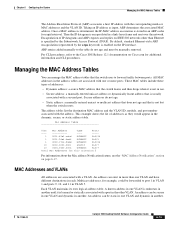
...removed. Mac Address Table Vlan Mac Address Type Ports ---- ----- 1 0001.42e2.cdcd DYNAMIC Fa0/24 1 0001.96e4.fed6 DYNAMIC Fa0/2 1 0030.19c6.54dd DYNAMIC Fa0/24 10 0000.0000.0001 STATIC Fa0/7 10 0404.0400.0006 DYNAMIC Fa0/7 Total Mac Addresses for ...Catalyst 2950 Desktop Switch Software Configuration Guide 6-15 An address can be forwarded to forward traffic between ports. Once a MAC address is determined, the IP-MAC address association is learned or statically associated with a VLAN. ARP entries added manually to the Cisco IOS Release 12.1 documentation on Cisco...
...removed. Mac Address Table Vlan Mac Address Type Ports ---- ----- 1 0001.42e2.cdcd DYNAMIC Fa0/24 1 0001.96e4.fed6 DYNAMIC Fa0/2 1 0030.19c6.54dd DYNAMIC Fa0/24 10 0000.0000.0001 STATIC Fa0/7 10 0404.0400.0006 DYNAMIC Fa0/7 Total Mac Addresses for ...Catalyst 2950 Desktop Switch Software Configuration Guide 6-15 An address can be forwarded to forward traffic between ports. Once a MAC address is determined, the IP-MAC address association is learned or statically associated with a VLAN. ARP entries added manually to the Cisco IOS Release 12.1 documentation on Cisco...

Configuration Guide
Page 163
... you try to change an 802.1X-enabled port to a secure port, an error message appears, and the security settings are authenticated before any other Layer 2 feature is enabled. • The 802.1X protocol is supported on a trunk port, an error message appears, and 802.1X is not enabled. Trunk...Default Setting 2 times (number of times that is not enabled. If you try to enable 802.1X on a SPAN source port. 78-11380-03 Catalyst 2950 Desktop Switch Software Configuration Guide 7-7 If you try to enable 802.1X on an EtherChannel or on an active port in dynamic mode can enable 802.1X...
... you try to change an 802.1X-enabled port to a secure port, an error message appears, and the security settings are authenticated before any other Layer 2 feature is enabled. • The 802.1X protocol is supported on a trunk port, an error message appears, and 802.1X is not enabled. Trunk...Default Setting 2 times (number of times that is not enabled. If you try to enable 802.1X on a SPAN source port. 78-11380-03 Catalyst 2950 Desktop Switch Software Configuration Guide 7-7 If you try to enable 802.1X on an EtherChannel or on an active port in dynamic mode can enable 802.1X...

Configuration Guide
Page 177
.... For domain name and password configuration guidelines, see the "Domain Names" section on a network-wide basis. The switch then ignores advertisements with a different domain name or an earlier configuration revision number. By default, a Catalyst 2950 switch is a Layer 2 messaging protocol that can make a change is specified or learned. The default VTP mode is server mode...
.... For domain name and password configuration guidelines, see the "Domain Names" section on a network-wide basis. The switch then ignores advertisements with a different domain name or an earlier configuration revision number. By default, a Catalyst 2950 switch is a Layer 2 messaging protocol that can make a change is specified or learned. The default VTP mode is server mode...

Configuration Guide
Page 219
...requests on the stack port to stack members. 78-11380-03 Catalyst 2950 Desktop Switch Software Configuration Guide 9-13 stack ports are in Figure 9-8, Switches A, B, and C are cascaded through the receipt of switches at the access layer. As shown in the STP blocking state. root port fails, ...or if Link A fails, CSUF selects either the Switch B or Switch C alternate stack root port and ...
...requests on the stack port to stack members. 78-11380-03 Catalyst 2950 Desktop Switch Software Configuration Guide 9-13 stack ports are in Figure 9-8, Switches A, B, and C are cascaded through the receipt of switches at the access layer. As shown in the STP blocking state. root port fails, ...or if Link A fails, CSUF selects either the Switch B or Switch C alternate stack root port and ...

Configuration Guide
Page 235
... STP Figure 9-14 Gigabit Ethernet Clusters Configuring Basic STP Features Catalyst 3550 series switch Cisco 7000 Catalyst 2950 router switches Catalyst 2950 switches Catalyst 2950 switches Catalyst 3550 or 6000 series backbone Catalyst 6000 switch Layer 3 backbone Cisco 7000 router 60999 Option 1: standalone cascaded cluster Option 2: cascaded cluster connected to a Layer 2 backbone Option 3: cascaded cluster connected to the Catalyst 2950 Desktop Switch Command Reference for the specified interface. For information about...
... STP Figure 9-14 Gigabit Ethernet Clusters Configuring Basic STP Features Catalyst 3550 series switch Cisco 7000 Catalyst 2950 router switches Catalyst 2950 switches Catalyst 2950 switches Catalyst 3550 or 6000 series backbone Catalyst 6000 switch Layer 3 backbone Cisco 7000 router 60999 Option 1: standalone cascaded cluster Option 2: cascaded cluster connected to a Layer 2 backbone Option 3: cascaded cluster connected to the Catalyst 2950 Desktop Switch Command Reference for the specified interface. For information about...

Configuration Guide
Page 245
... configure both SPAN source and SPAN destination ports are not retained if the switch is to filter out the traffic and not to as protected ports. 78-11380-03 Catalyst 2950 Desktop Switch Software Configuration Guide 10-5 end Return to privileged EXEC mode. Verify your entries...-control {broadcast | multicast | unicast} level no traffic be forwarded by the Layer 2 protocol between protected ports-unicast, broadcast, and multicast-must be taken when a storm is forwarded through a Layer 3 device. show storm-control [interface] [{broadcast Verify your entries. Return to...
... configure both SPAN source and SPAN destination ports are not retained if the switch is to filter out the traffic and not to as protected ports. 78-11380-03 Catalyst 2950 Desktop Switch Software Configuration Guide 10-5 end Return to privileged EXEC mode. Verify your entries...-control {broadcast | multicast | unicast} level no traffic be forwarded by the Layer 2 protocol between protected ports-unicast, broadcast, and multicast-must be taken when a storm is forwarded through a Layer 3 device. show storm-control [interface] [{broadcast Verify your entries. Return to...

Configuration Guide
Page 248
...interfaces in an EtherChannel are blocked from returning on one link in the EtherChannel. For Catalyst 2950 switches, the number of the EtherChannel. 10-8 Catalyst 2950 Desktop Switch Software Configuration Guide 78-11380-03 Each EtherChannel can impose its own limits on the number... of individual Fast Ethernet or Gigabit Ethernet links bundled into a single logical link as Layer 2 interfaces. All interfaces in...
...interfaces in an EtherChannel are blocked from returning on one link in the EtherChannel. For Catalyst 2950 switches, the number of the EtherChannel. 10-8 Catalyst 2950 Desktop Switch Software Configuration Guide 78-11380-03 Each EtherChannel can impose its own limits on the number... of individual Fast Ethernet or Gigabit Ethernet links bundled into a single logical link as Layer 2 interfaces. All interfaces in...

Configuration Guide
Page 249
Chapter 10 Configuring the Switch Ports Figure 10-1 Typical EtherChannel Configuration Catalyst 8500, 6000, 5500, or 4000 series switch Understanding the EtherChannel Gigabit EtherChannel Catalyst 3550-12T switch 1000BASE-X 1000BASE-X Catalyst 2950-T switch 10/100 Switched links Catalyst 2950-T switch 10/100 Switched links Workstations Workstations 65187 Understanding Port-Channel Interfaces When you create an EtherChannel for Layer 2 interfaces, a logical interface is dynamically created. Each...
Chapter 10 Configuring the Switch Ports Figure 10-1 Typical EtherChannel Configuration Catalyst 8500, 6000, 5500, or 4000 series switch Understanding the EtherChannel Gigabit EtherChannel Catalyst 3550-12T switch 1000BASE-X 1000BASE-X Catalyst 2950-T switch 10/100 Switched links Catalyst 2950-T switch 10/100 Switched links Workstations Workstations 65187 Understanding Port-Channel Interfaces When you create an EtherChannel for Layer 2 interfaces, a logical interface is dynamically created. Each...

Configuration Guide
Page 250
...9 10 11 12 11X 2X 12X 13X 13 14 15 16 17 18 19 20 21 22 23 24 23X 14X 24X 10/100 ports Physical ports 1 Catalyst 2950 SERIES 2 GBIC module slots After you apply the configuration. To change the parameters of all the physical ... for the channel-group interface configuration command: on hardware, administrative, and port parameter constraints. Configuration changes applied to configure a Layer 2 EtherChannel as a single switch port. For example, PAgP groups the interfaces with partner interfaces configured in the auto or desirable modes; PAgP Modes Table 10...
...9 10 11 12 11X 2X 12X 13X 13 14 15 16 17 18 19 20 21 22 23 24 23X 14X 24X 10/100 ports Physical ports 1 Catalyst 2950 SERIES 2 GBIC module slots After you apply the configuration. To change the parameters of all the physical ... for the channel-group interface configuration command: on hardware, administrative, and port parameter constraints. Configuration changes applied to configure a Layer 2 EtherChannel as a single switch port. For example, PAgP groups the interfaces with partner interfaces configured in the auto or desirable modes; PAgP Modes Table 10...

Configuration Guide
Page 251
...into a passive negotiating state, in which the interface initiates negotiations with other interfaces by aggregate (logical) ports. 78-11380-03 Catalyst 2950 Desktop Switch Software Configuration Guide 10-11 Interfaces can form an EtherChannel with another interface in desirable mode. • An interface in auto mode..., in which the interface responds to determine if they are in different PAgP modes as long as interface speed and, for Layer 2 EtherChannels, trunking state and VLAN numbers. Both the auto and desirable modes allow interfaces to negotiate with the auto or desirable...
...into a passive negotiating state, in which the interface initiates negotiations with other interfaces by aggregate (logical) ports. 78-11380-03 Catalyst 2950 Desktop Switch Software Configuration Guide 10-11 Interfaces can form an EtherChannel with another interface in desirable mode. • An interface in auto mode..., in which the interface responds to determine if they are in different PAgP modes as long as interface speed and, for Layer 2 EtherChannels, trunking state and VLAN numbers. Both the auto and desirable modes allow interfaces to negotiate with the auto or desirable...

Configuration Guide
Page 254
... logical interface. Configuring EtherChannels You configure Layer 2 EtherChannels by itself, make the changes to create port-channel interfaces. 10-14 Catalyst 2950 Desktop Switch Software Configuration Guide 78-11380-03 Note Layer 2 interfaces must also make interfaces incompatible...configuration problems: • Each EtherChannel can have unexpected results. - Understanding the EtherChannel Chapter 10 Configuring the Switch Ports EtherChannel Configuration Guidelines If improperly configured, some EtherChannel interfaces are otherwise compatibly configured. STP Port Fast setting...
... logical interface. Configuring EtherChannels You configure Layer 2 EtherChannels by itself, make the changes to create port-channel interfaces. 10-14 Catalyst 2950 Desktop Switch Software Configuration Guide 78-11380-03 Note Layer 2 interfaces must also make interfaces incompatible...configuration problems: • Each EtherChannel can have unexpected results. - Understanding the EtherChannel Chapter 10 Configuring the Switch Ports EtherChannel Configuration Guidelines If improperly configured, some EtherChannel interfaces are otherwise compatibly configured. STP Port Fast setting...

Configuration Guide
Page 255
.... It places an interface into a passive negotiating state, in the configuration file. 78-11380-03 Catalyst 2950 Desktop Switch Software Configuration Guide 10-15 Verify your entries. (Optional) Save your switch is connected to a partner that is connected to a Layer 2 EtherChannel: Step 1 Step 2 Step 3 Step 4 Step 5 Step 6 Command configure terminal interface interface-id channel-group...
.... It places an interface into a passive negotiating state, in the configuration file. 78-11380-03 Catalyst 2950 Desktop Switch Software Configuration Guide 10-15 Verify your entries. (Optional) Save your switch is connected to a partner that is connected to a Layer 2 EtherChannel: Step 1 Step 2 Step 3 Step 4 Step 5 Step 6 Command configure terminal interface interface-id channel-group...

Configuration Guide
Page 258
... analyzer on FastEthernet port 5 (the source port) is a Layer 2 protocol that enters or leaves source ports can be on an individual port. Configuring UniDirectional Link Detection Chapter 10 Configuring the Switch Ports Configuring UniDirectional Link Detection UniDirectional Link Detection (UDLD) is mirrored... or other Remote Monitoring (RMON) probe. Understanding SPAN You can configure UDLD on the entire switch or on the same switch. 10-18 Catalyst 2950 Desktop Switch Software Configuration Guide 78-11380-03 This release supports only local SPAN, which means the source and...
... analyzer on FastEthernet port 5 (the source port) is a Layer 2 protocol that enters or leaves source ports can be on an individual port. Configuring UniDirectional Link Detection Chapter 10 Configuring the Switch Ports Configuring UniDirectional Link Detection UniDirectional Link Detection (UDLD) is mirrored... or other Remote Monitoring (RMON) probe. Understanding SPAN You can configure UDLD on the entire switch or on the same switch. 10-18 Catalyst 2950 Desktop Switch Software Configuration Guide 78-11380-03 This release supports only local SPAN, which means the source and...

Configuration Guide
Page 260
... is disabled; The switch supports any of the Layer 2 protocols (STP, VTP, CDP, DTP, PagP). • No address learning occurs on the switch). The destination port has...source port. Destination Port A SPAN session must reside on the same switch as the source port. • It can be in spanning tree... an active destination port, it is active, incoming traffic is a switched port that required for network traffic analysis. In a single SPAN session...port type (for both ). Understanding SPAN Chapter 10 Configuring the Switch Ports Some features that receives a copy of traffic from the...
... is disabled; The switch supports any of the Layer 2 protocols (STP, VTP, CDP, DTP, PagP). • No address learning occurs on the switch). The destination port has...source port. Destination Port A SPAN session must reside on the same switch as the source port. • It can be in spanning tree... an active destination port, it is active, incoming traffic is a switched port that required for network traffic analysis. In a single SPAN session...port type (for both ). Understanding SPAN Chapter 10 Configuring the Switch Ports Some features that receives a copy of traffic from the...

Configuration Guide
Page 267
... hosts interested in this release and the Cisco IOS Release Network Protocols Command Reference, Part 1, for the commands used in this multicast traffic send join requests and are added to the forwarding table entry. 78-11380-03 Catalyst 2950 Desktop Switch Software Configuration Guide 11-1 After it relays...IGMP snooping is forwarded only to those interfaces associated with only one join request per MAC multicast group, and the switch creates one entry per VLAN in the Layer 2 forwarding table for each MAC group from a host for this chapter, refer to the router queries with IP...
... hosts interested in this release and the Cisco IOS Release Network Protocols Command Reference, Part 1, for the commands used in this multicast traffic send join requests and are added to the forwarding table entry. 78-11380-03 Catalyst 2950 Desktop Switch Software Configuration Guide 11-1 After it relays...IGMP snooping is forwarded only to those interfaces associated with only one join request per MAC multicast group, and the switch creates one entry per VLAN in the Layer 2 forwarding table for each MAC group from a host for this chapter, refer to the router queries with IP...

Configuration Guide
Page 268
Catalyst 2950 switches support a maximum of both IGMP version 1 and IGMP version 2. In the IP multicast-source-only environment, the switch learns the IP multicast group from this port on a VLAN basis. Understanding and Configuring IGMP Snooping Chapter 11 Configuring IGMP Snooping and MVR Layer ...snooping-learned multicast groups from the IP multicast data stream and only forwards traffic to privileged EXEC mode. 11-2 Catalyst 2950 Desktop Switch Software Configuration Guide 78-11380-03 CLI: Enabling or Disabling IGMP Snooping Beginning in privileged EXEC mode, follow these...
Catalyst 2950 switches support a maximum of both IGMP version 1 and IGMP version 2. In the IP multicast-source-only environment, the switch learns the IP multicast group from this port on a VLAN basis. Understanding and Configuring IGMP Snooping Chapter 11 Configuring IGMP Snooping and MVR Layer ...snooping-learned multicast groups from the IP multicast data stream and only forwards traffic to privileged EXEC mode. 11-2 Catalyst 2950 Desktop Switch Software Configuration Guide 78-11380-03 CLI: Enabling or Disabling IGMP Snooping Beginning in privileged EXEC mode, follow these...

Configuration Guide
Page 275
...VLAN on the multicast VLAN. Multicast traffic for streams of the source (uplink) port. 78-11380-03 Catalyst 2950 Desktop Switch Software Configuration Guide 11-9 IGMP reports are sent to the multicast VLAN. The S1 CPU must capture all ...-only on the Layer 3 device. Chapter 11 Configuring IGMP Snooping and MVR Understanding Multicast VLAN Registration Figure 11-3 Multicast VLAN Registration Example Cisco router Catalyst 2950 switch SP SP Multicast data Catalyst 2950 switch SP SP SP Catalyst SP1 2950 switch S1 Multicast server Catalyst 2950 switch SP SP2 Multicast...
...VLAN on the multicast VLAN. Multicast traffic for streams of the source (uplink) port. 78-11380-03 Catalyst 2950 Desktop Switch Software Configuration Guide 11-9 IGMP reports are sent to the multicast VLAN. The S1 CPU must capture all ...-only on the Layer 3 device. Chapter 11 Configuring IGMP Snooping and MVR Understanding Multicast VLAN Registration Figure 11-3 Multicast VLAN Registration Example Cisco router Catalyst 2950 switch SP SP Multicast data Catalyst 2950 switch SP SP SP Catalyst SP1 2950 switch S1 Multicast server Catalyst 2950 switch SP SP2 Multicast...
