
Service Manual
Page 2
...CONTAINED HEREIN SHOULD BE DIRECTED TO THE COPIER SERVICE DEPARTMENT OF THE SALES COMPANY. COPYRIGHT © 1999 CANON INC. Prepared by OFFICE IMAGING PRODUCTS TECHNICAL SUPPORT DIVISION CANON INC. 5-1, Hakusan 7-chome, Toride-shi, Ibaraki 302-8501 Japan COPYRIGHT © 1999 CANON INC. CANON PC800s/900s REV.0 AUG. 1999 ... MAY VARY SLIGHTLY FROM ACTUAL MACHINE VALUES OR THOSE FOUND IN ADVERTISING AND OTHER PRINTED MATTER. IMPORTANT THIS DOCUMENTATION IS PUBLISHED BY CANON INC., JAPAN, TO SERVE AS A SOURCE OF REFERENCE FOR WORK IN THE FIELD. THIS DOCUMENTATION IS INTENDED FOR ALL SALES ...
...CONTAINED HEREIN SHOULD BE DIRECTED TO THE COPIER SERVICE DEPARTMENT OF THE SALES COMPANY. COPYRIGHT © 1999 CANON INC. Prepared by OFFICE IMAGING PRODUCTS TECHNICAL SUPPORT DIVISION CANON INC. 5-1, Hakusan 7-chome, Toride-shi, Ibaraki 302-8501 Japan COPYRIGHT © 1999 CANON INC. CANON PC800s/900s REV.0 AUG. 1999 ... MAY VARY SLIGHTLY FROM ACTUAL MACHINE VALUES OR THOSE FOUND IN ADVERTISING AND OTHER PRINTED MATTER. IMPORTANT THIS DOCUMENTATION IS PUBLISHED BY CANON INC., JAPAN, TO SERVE AS A SOURCE OF REFERENCE FOR WORK IN THE FIELD. THIS DOCUMENTATION IS INTENDED FOR ALL SALES ...
Service Manual
Page 7
...Scanner Drive Assembly .... 3-13 B. Copier 1-2 B. ADF 1-8 III. ROUTINE MAINTENANCE BY THE USER 1-17 VI. BASIC OPERATIONS 2-1 A. External View 1-10 B. Cross Section 1-13 IV. Exposure System 3-37 COPYRIGHT © 1999 CANON INC. Controlling the Scanning Lamp 3-9...CONTENTS CHAPTER 1 GENERAL DESCRIPTION I. SPECIFICATIONS 1-2 A. IMAGE FORMATION 1-20 A. DISASSEMBLY/ASSEMBLY ..... 3-12 A. Varying the Reproduction Ratio 3-2 C. CANON PC800s/900s REV.0 AUG. 1999 PRINTED IN JAPAN (IMPRIME AU JAPON) v NAMES OF PARTS 1-10 A. Outline of Operations 2-3 D. ...
...Scanner Drive Assembly .... 3-13 B. Copier 1-2 B. ADF 1-8 III. ROUTINE MAINTENANCE BY THE USER 1-17 VI. BASIC OPERATIONS 2-1 A. External View 1-10 B. Cross Section 1-13 IV. Exposure System 3-37 COPYRIGHT © 1999 CANON INC. Controlling the Scanning Lamp 3-9...CONTENTS CHAPTER 1 GENERAL DESCRIPTION I. SPECIFICATIONS 1-2 A. IMAGE FORMATION 1-20 A. DISASSEMBLY/ASSEMBLY ..... 3-12 A. Varying the Reproduction Ratio 3-2 C. CANON PC800s/900s REV.0 AUG. 1999 PRINTED IN JAPAN (IMPRIME AU JAPON) v NAMES OF PARTS 1-10 A. Outline of Operations 2-3 D. ...
Service Manual
Page 11
Copier 1-2 B. ROUTINE MAINTENANCE BY THE USER 1-17 VI. I. ADF 1-8 III. USING THE MACHINE 1-15 A. IMAGE FORMATION 1-20 A. CANON PC800s/900s REV.0 AUG. 1999 PRINTED IN JAPAN (IMPRIME AU JAPON) FEATURES 1-1 II. SPECIFICATIONS 1-2 A. External View 1-10 B. Control Panel 1-15 V. NAMES OF PARTS 1-10 A. Outline 1-20 COPYRIGHT © 1999 CANON INC. CHAPTER 1 GENERAL DESCRIPTION This chapter provides specifications of the machine, instructions on how to operate the machine, and an outline of copying process. Cross Section 1-13 IV.
Copier 1-2 B. ROUTINE MAINTENANCE BY THE USER 1-17 VI. I. ADF 1-8 III. USING THE MACHINE 1-15 A. IMAGE FORMATION 1-20 A. CANON PC800s/900s REV.0 AUG. 1999 PRINTED IN JAPAN (IMPRIME AU JAPON) FEATURES 1-1 II. SPECIFICATIONS 1-2 A. External View 1-10 B. Control Panel 1-15 V. NAMES OF PARTS 1-10 A. Outline 1-20 COPYRIGHT © 1999 CANON INC. CHAPTER 1 GENERAL DESCRIPTION This chapter provides specifications of the machine, instructions on how to operate the machine, and an outline of copying process. Cross Section 1-13 IV.
Service Manual
Page 13
...as long as a business card. 5. ADF Type • Continuous copying is 0 sec (at maximum (1/100 to make jam removal easy. 8. COPYRIGHT © 1999 CANON INC. Personal Copier with existing Canon machines). 3. The user may contain as many as a single entity (cartridge). Various Paper Sizes • The paper may be between 70% and 141... for Simple Maintenance • The photosensitive drum, toner case, charging roller, developing assembly, and cleaning assembly are constructed as 550 sheets of the ADF. CANON PC800s/900s REV.0 AUG. 1999 PRINTED IN JAPAN (IMPRIME AU JAPON) 1-1
...as long as a business card. 5. ADF Type • Continuous copying is 0 sec (at maximum (1/100 to make jam removal easy. 8. COPYRIGHT © 1999 CANON INC. Personal Copier with existing Canon machines). 3. The user may contain as many as a single entity (cartridge). Various Paper Sizes • The paper may be between 70% and 141... for Simple Maintenance • The photosensitive drum, toner case, charging roller, developing assembly, and cleaning assembly are constructed as 550 sheets of the ADF. CANON PC800s/900s REV.0 AUG. 1999 PRINTED IN JAPAN (IMPRIME AU JAPON) 1-1
Service Manual
Page 14
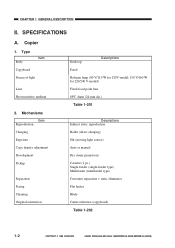
CHAPTER 1 GENERAL DESCRIPTION II. CANON PC800s/900s REV.0 AUG. 1999 PRINTED IN JAPAN (IMPRIME AU JAPON) Mechanisms Item Reproduction Charging Exposure Copy density adjustment Development Pickup Separation Fixing Cleaning Original ...) Cassette (1 pc.) Single-feeder (single-feeder type) Multifeeder (multifeeder type) Curvature separation + static eliminator Flat heater Blade Center reference (copyboard) Table 1-202 1-2 COPYRIGHT © 1999 CANON INC. SPECIFICATIONS A. Type Item Body Copyboard Source of light Lens Photosensitive medium...
CHAPTER 1 GENERAL DESCRIPTION II. CANON PC800s/900s REV.0 AUG. 1999 PRINTED IN JAPAN (IMPRIME AU JAPON) Mechanisms Item Reproduction Charging Exposure Copy density adjustment Development Pickup Separation Fixing Cleaning Original ...) Cassette (1 pc.) Single-feeder (single-feeder type) Multifeeder (multifeeder type) Curvature separation + static eliminator Flat heater Blade Center reference (copyboard) Table 1-202 1-2 COPYRIGHT © 1999 CANON INC. SPECIFICATIONS A. Type Item Body Copyboard Source of light Lens Photosensitive medium...
Service Manual
Page 207
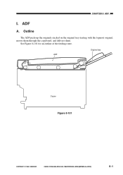
ADF A. CANON PC800s/900s REV.0 AUG. 1999 PRINTED IN JAPAN (IMPRIME AU JAPON) 8-1 See Figure 8-101 for an outline of the feeding route. CHAPTER 8 ADF I. ADF Original tray Copier Figure 8-101 COPYRIGHT © 1999 CANON INC. Outline The ADF picks up the originals stacked on the original tray starting with the topmost original, moves them through the copyboard, and delivers them.
ADF A. CANON PC800s/900s REV.0 AUG. 1999 PRINTED IN JAPAN (IMPRIME AU JAPON) 8-1 See Figure 8-101 for an outline of the feeding route. CHAPTER 8 ADF I. ADF Original tray Copier Figure 8-101 COPYRIGHT © 1999 CANON INC. Outline The ADF picks up the originals stacked on the original tray starting with the topmost original, moves them through the copyboard, and delivers them.
Service Manual
Page 208
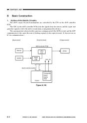
...ADFcontroller PCB CPU (Q1) ROM (Q2) 24V 5V Motor Serial communication Copier Composite power supply PCB Figure 8-102 8-2 COPYRIGHT © 1999 CANON INC. CHAPTER 8 ADF B Basic Construction 1. The CPU on the ADF controller PCB. CANON PC800s/900s REV.0 AUG. 1999 PRINTED IN JAPAN (IMPRIME AU JAPON...) The copying modes selected on the copier are controlled by the CPU on the ...
...ADFcontroller PCB CPU (Q1) ROM (Q2) 24V 5V Motor Serial communication Copier Composite power supply PCB Figure 8-102 8-2 COPYRIGHT © 1999 CANON INC. CHAPTER 8 ADF B Basic Construction 1. The CPU on the ADF controller PCB. CANON PC800s/900s REV.0 AUG. 1999 PRINTED IN JAPAN (IMPRIME AU JAPON...) The copying modes selected on the copier are controlled by the CPU on the ...
Service Manual
Page 209
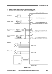
...-blocking plate is at sensor) J3-1 -2 -3 -4 See p. 8-15. -5 J3-6 -7 See p. 8-14. Inputs to and Outputs from the ADF Controller PCB a. J114 J202 J2 Serial communication Copier *Negative logic. Figure 8-103 COPYRIGHT © 1999 CANON INC. CANON PC800s/900s REV.0 AUG. 1999 PRINTED IN JAPAN (IMPRIME AU JAPON) 8-3 CHAPTER 8 ADF 2.
...-blocking plate is at sensor) J3-1 -2 -3 -4 See p. 8-15. -5 J3-6 -7 See p. 8-14. Inputs to and Outputs from the ADF Controller PCB a. J114 J202 J2 Serial communication Copier *Negative logic. Figure 8-103 COPYRIGHT © 1999 CANON INC. CANON PC800s/900s REV.0 AUG. 1999 PRINTED IN JAPAN (IMPRIME AU JAPON) 8-3 CHAPTER 8 ADF 2.
Service Manual
Page 220
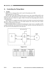
... drive signal (PM1) '1' '0' '1' '0' Table 8-102 Pickup roller rotation Braked Picking up Delivering At reset (free) 8-14 COPYRIGHT © 1999 CANON INC. The CPU (Q1) on the copier and stop the pickup motor at the same time. The pickup motor rotates clockwise or counterclockwise according to the motor driver (Q5...the limiter function is a diagram of these two signals. (Table 8-102 shows how the pickup motor rotates for the pickup motor (M2). CANON PC800s/900s REV.0 AUG. 1999 PRINTED IN JAPAN (IMPRIME AU JAPON) Outline Figure 8-121 is activated, the pickup motor cannot rotate as...
... drive signal (PM1) '1' '0' '1' '0' Table 8-102 Pickup roller rotation Braked Picking up Delivering At reset (free) 8-14 COPYRIGHT © 1999 CANON INC. The CPU (Q1) on the copier and stop the pickup motor at the same time. The pickup motor rotates clockwise or counterclockwise according to the motor driver (Q5...the limiter function is a diagram of these two signals. (Table 8-102 shows how the pickup motor rotates for the pickup motor (M2). CANON PC800s/900s REV.0 AUG. 1999 PRINTED IN JAPAN (IMPRIME AU JAPON) Outline Figure 8-121 is activated, the pickup motor cannot rotate as...
Service Manual
Page 223
...) turns off when the ADF is opened . The 5V supply will continue to keep each sensor powered even when the ADF is supplied by the copier with 5 V and 24 V. ADF switch (MS1) J6-1 COM J6-2 NO J101-1 24V J1-1 Composite power supply PCB J101-3 5V J1-3 ...Circuitbreaker (CB1) Fuse resistor (R1) Logic Copier ADF controller PCB Figure 8-124 Belt motor (M1) Pickup motor (M2) Delivery sensor (PI1) Registration sensor (PI2) Original placement sensor (PI3) COPYRIGHT © 1999 CANON INC.
...) turns off when the ADF is opened . The 5V supply will continue to keep each sensor powered even when the ADF is supplied by the copier with 5 V and 24 V. ADF switch (MS1) J6-1 COM J6-2 NO J101-1 24V J1-1 Composite power supply PCB J101-3 5V J1-3 ...Circuitbreaker (CB1) Fuse resistor (R1) Logic Copier ADF controller PCB Figure 8-124 Belt motor (M1) Pickup motor (M2) Delivery sensor (PI1) Registration sensor (PI2) Original placement sensor (PI3) COPYRIGHT © 1999 CANON INC.
Service Manual
Page 226
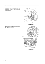
CHAPTER 8 ADF 6) Disconnect the two connectors [8], and remove the screw [9]; CANON PC800s/900s REV.0 AUG. 1999 PRINTED IN JAPAN (IMPRIME AU JAPON) then, remove the cable bush [10]. [10] [8] [9] 7) Remove the two lockpin [11], and remove the ADF from the copier. [8] Figure 8-204 [11] [11] Figure 8-205 8-20 COPYRIGHT © 1999 CANON INC.
CHAPTER 8 ADF 6) Disconnect the two connectors [8], and remove the screw [9]; CANON PC800s/900s REV.0 AUG. 1999 PRINTED IN JAPAN (IMPRIME AU JAPON) then, remove the cable bush [10]. [10] [8] [9] 7) Remove the two lockpin [11], and remove the ADF from the copier. [8] Figure 8-204 [11] [11] Figure 8-205 8-20 COPYRIGHT © 1999 CANON INC.
Service Manual
Page 227
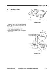
B. Removing the ADF.") 2) Remove the feeding roller [1] from the copier. (See "A. CANON PC800s/900s REV.0 AUG. 1999 PRINTED IN JAPAN (IMPRIME AU JAPON) 8-21 External Covers CHAPTER 8 ADF [1] Remove the covers as follows when cleaning, checking, or repairing the inside of the machine: 1) Remove the ADF from the bushing [2]. [2] [1] Upper cover [2] Lower cover Figure 8-206 [1] [2] [1] [2] Figure 8-207 COPYRIGHT © 1999 CANON INC.
B. Removing the ADF.") 2) Remove the feeding roller [1] from the copier. (See "A. CANON PC800s/900s REV.0 AUG. 1999 PRINTED IN JAPAN (IMPRIME AU JAPON) 8-21 External Covers CHAPTER 8 ADF [1] Remove the covers as follows when cleaning, checking, or repairing the inside of the machine: 1) Remove the ADF from the bushing [2]. [2] [1] Upper cover [2] Lower cover Figure 8-206 [1] [2] [1] [2] Figure 8-207 COPYRIGHT © 1999 CANON INC.
Service Manual
Page 244
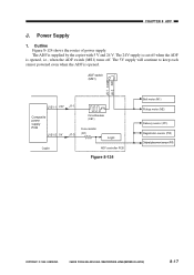
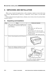
... copies. A. Unpacking and Installation Step 1 2 Work Checks and remarks Take out the copier and the attachments from a cold to warm place, droplets of water tend to form on its surface. UNPACKING AND INSTALLATION When a piece of the machine. CANON PC800s/900s REV.0 AUG. 1999 PRINTED IN JAPAN (IMPRIME AU JAPON) CHAPTER 9 INSTALLATION...) from the left of metal is known as "condensation" and, in from a cold place, leave it . This phenomenon is brought in step 9. 9-2 COPYRIGHT © 1999 CANON INC.
... copies. A. Unpacking and Installation Step 1 2 Work Checks and remarks Take out the copier and the attachments from a cold to warm place, droplets of water tend to form on its surface. UNPACKING AND INSTALLATION When a piece of the machine. CANON PC800s/900s REV.0 AUG. 1999 PRINTED IN JAPAN (IMPRIME AU JAPON) CHAPTER 9 INSTALLATION...) from the left of metal is known as "condensation" and, in from a cold place, leave it . This phenomenon is brought in step 9. 9-2 COPYRIGHT © 1999 CANON INC.
Service Manual
Page 267
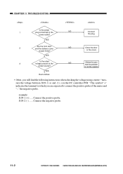
... expected to connect the positive probe of the meter and "-," the negative probe. CANON PC800s/900s REV.0 AUG. 1999 PRINTED IN JAPAN (IMPRIME AU JAPON) is not the copier's. or the cover. Connect the negative probe. 11-2 COPYRIGHT © 1999 CANON INC. The symbol "+" indicates the terminal to the NO power outlet? Connect...
... expected to connect the positive probe of the meter and "-," the negative probe. CANON PC800s/900s REV.0 AUG. 1999 PRINTED IN JAPAN (IMPRIME AU JAPON) is not the copier's. or the cover. Connect the negative probe. 11-2 COPYRIGHT © 1999 CANON INC. The symbol "+" indicates the terminal to the NO power outlet? Connect...

Service Manual
Page 270
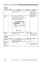
Mechanical 1. Leading Edge Non-Image Width Make adjustments so that the width is copied in Direct. Copier a. VR105 J131 J101 J102 J101 J130 J114 J102 VR104VR105VR106 VR107 VR103VR102 J107 J103 J104 J105 J109 J106 Figure 11-202 Turing VR105... and Leading Edge Non-Image Width Direction of VR105 Clockwise Counterclockwise Leading edge non-image width Decreases Increases Table 11-201 COPYRIGHT © 1999 CANON INC. CANON PC800s/900s REV.0 AUG. 1999 PRINTED IN JAPAN (IMPRIME AU JAPON) 11-5 STANDARDS AND ADJUSTMENTS A. CHAPTER 11 TROUBLESHOOTING II. Caution: If ...
Mechanical 1. Leading Edge Non-Image Width Make adjustments so that the width is copied in Direct. Copier a. VR105 J131 J101 J102 J101 J130 J114 J102 VR104VR105VR106 VR107 VR103VR102 J107 J103 J104 J105 J109 J106 Figure 11-202 Turing VR105... and Leading Edge Non-Image Width Direction of VR105 Clockwise Counterclockwise Leading edge non-image width Decreases Increases Table 11-201 COPYRIGHT © 1999 CANON INC. CANON PC800s/900s REV.0 AUG. 1999 PRINTED IN JAPAN (IMPRIME AU JAPON) 11-5 STANDARDS AND ADJUSTMENTS A. CHAPTER 11 TROUBLESHOOTING II. Caution: If ...
Service Manual
Page 331
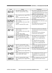
... supply PCB Step 1 2 Checks Turn off and then on the power. NO Replace the composite power supply PCB. 11-66 11-66 COPYRIGHT © 1999 CANON INC. Is the voltage about 5V? YES End. Is the problem corrected? YES/NO Action YES End. Is the probrem corrected? 5V power supply 2 Set... the matter to the 20VDC range, and connect the + probe to the copier ground. CHAPTER 11 TROUBLESHOOTING 12 E400 Cause Step 1 Checks Turn off and then on the ADF controller PCB and the - YES/NO YES NO Action...
... supply PCB Step 1 2 Checks Turn off and then on the power. NO Replace the composite power supply PCB. 11-66 11-66 COPYRIGHT © 1999 CANON INC. Is the voltage about 5V? YES End. Is the problem corrected? YES/NO Action YES End. Is the probrem corrected? 5V power supply 2 Set... the matter to the 20VDC range, and connect the + probe to the copier ground. CHAPTER 11 TROUBLESHOOTING 12 E400 Cause Step 1 Checks Turn off and then on the ADF controller PCB and the - YES/NO YES NO Action...
Service Manual
Page 352
...composite power supply PCB is detected. • The interval between zero-cross signals is in excess of the allowed interval. • The communication with the copier is monitored at all times. • During a copying run, the +24 V power deviates from the setting value twice in succession. • ... are locked • The scanner/lens drive motor (M2) is faulty. • The DC controller PCB is faulty. without error code indication. CANON PC800s/900s REV.0 AUG. 1999 PRINTED IN JAPAN (IMPRIME AU JAPON) 11-87 Description • The rotation of the main motor deviates (indicated ...
...composite power supply PCB is detected. • The interval between zero-cross signals is in excess of the allowed interval. • The communication with the copier is monitored at all times. • During a copying run, the +24 V power deviates from the setting value twice in succession. • ... are locked • The scanner/lens drive motor (M2) is faulty. • The DC controller PCB is faulty. without error code indication. CANON PC800s/900s REV.0 AUG. 1999 PRINTED IN JAPAN (IMPRIME AU JAPON) 11-87 Description • The rotation of the main motor deviates (indicated ...
Service Manual
Page 357
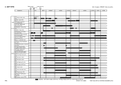
...sensor (PS2) 5 Lens solenoid (SL3) 6 Pickup clutch solenoid (SL1) 7 Cassette pickup solenoid (SL5) Vertical path roller 8 paper sensor (PS4) 9 Registration clutch solenoid (SL2) 10 Copier Pre-registration roller paper sensor (Q751) 11 Scanning lamp (LA1) 12 Primary AC bias 13 Primary DC bias 14 Developing AC bias 15 Developing DC... fan (FM1) 20 Delivery sensor (PS3) Preparing for pickup : Scanner / lens drive motor (reverse) / Pickup motor (reverse) / Belt motor (reverse) COPYRIGHT © 1999 CANON INC. CANON PC800s/900s REV.0 AUG. 1999 PRINTED IN JAPAN (IMPRIME AU JAPON)
...sensor (PS2) 5 Lens solenoid (SL3) 6 Pickup clutch solenoid (SL1) 7 Cassette pickup solenoid (SL5) Vertical path roller 8 paper sensor (PS4) 9 Registration clutch solenoid (SL2) 10 Copier Pre-registration roller paper sensor (Q751) 11 Scanning lamp (LA1) 12 Primary AC bias 13 Primary DC bias 14 Developing AC bias 15 Developing DC... fan (FM1) 20 Delivery sensor (PS3) Preparing for pickup : Scanner / lens drive motor (reverse) / Pickup motor (reverse) / Belt motor (reverse) COPYRIGHT © 1999 CANON INC. CANON PC800s/900s REV.0 AUG. 1999 PRINTED IN JAPAN (IMPRIME AU JAPON)
Service Manual
Page 360
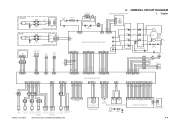
...NF1 NOISE FILTER PCB Thermal fuse 1 FU1 Scanning lamp LA1 J17 FT6 FT5 Fixing heater H1 J16 1 2 J15 J2 FU2 Thermal fuse 2 J434 11 22 C. Copier J901 1 2 3 4 Main motor M1 M BP701 BP705 PR +24VU GND MMD MLOCK [120V] H N FT2 FT4 FT1 FT3 J1 DS1 Door switch JP502 ...Single-feeder position sensor paper sensor (Single-feeder type only) SL5 Cassette pickup solenoid PS4 Vertical path roller paper sensor COPYRIGHT © 1999 CANON INC. CANON PC800s/900s REV.0 AUG. 1999 PRINTED IN JAPAN (IMPRIME AU JAPON) J751 3 2 1 Q751 Pre-registration roller paper sensor SENSOR PCB...
...NF1 NOISE FILTER PCB Thermal fuse 1 FU1 Scanning lamp LA1 J17 FT6 FT5 Fixing heater H1 J16 1 2 J15 J2 FU2 Thermal fuse 2 J434 11 22 C. Copier J901 1 2 3 4 Main motor M1 M BP701 BP705 PR +24VU GND MMD MLOCK [120V] H N FT2 FT4 FT1 FT3 J1 DS1 Door switch JP502 ...Single-feeder position sensor paper sensor (Single-feeder type only) SL5 Cassette pickup solenoid PS4 Vertical path roller paper sensor COPYRIGHT © 1999 CANON INC. CANON PC800s/900s REV.0 AUG. 1999 PRINTED IN JAPAN (IMPRIME AU JAPON) J751 3 2 1 Q751 Pre-registration roller paper sensor SENSOR PCB...


